Note : Les descriptions sont présentées dans la langue officielle dans laquelle elles ont été soumises.
CA 02968810 2017-05-24
WO 2016/089209
PCT/NL2015/050841
Title: Sensor separation apparatus and method
The invention generally relates to separation of particles, in
particular in recycling.
Separation apparatus are known in the prior art and they are
typically used in raw materials processing for the classification of mixed
streams of particles of recycling material into streams with particles of
different types of material. The known sensor separation apparatus
comprises an identifier, in particular a sensor that analyses a group of
particles in order to asses the type of each individual particle. After the
particles of the relevant type have been identified by the sensor, a separator
is activated that physically separates the identified particles from the group
of particles, for example a series of nozzles is actuated so that they
initiate
jets of air that eject the identified particles from the stream such that they
are separated from the group of particles.
A disadvantage of the sensor separation apparatus known in the
art is that they are not very accurate. In particular, the air jets will
accidentally hit and eject not just the identified particles, but also
neighboring non-identified particles which may be of a different type.
Especially, when the particles are closely arranged in the group this
decreases the accuracy of the known sensor separation apparatus. A
solution in the art is to arrange the particles very sparsely in the group to
avoid accidentally hitting and ejecting neighboring particles by the jet of
air.
However, this lowers the capacity and affects the economy of the process.
For example, economic recycling of a mixed stream of smaller particles of
physically similar or identical particles, e.g. shredded particles of a
plastic
material, e.g. PET or PE, having different colors and a maximum dimension
of several mm, e.g. 10 mm or less.
EP2343136B1 discloses a separation method intended to extract a
target, using viscosity of a liquid, from a separation subject in which the
CA 02968810 2017-05-24
WO 2016/089209 PCT/NL2015/050841
2
target and a non-target are mixed. The disclosed method comprises
distinguishing the target from the non-target; obtaining positional
information of the target distinguished in the distinguishing, attaching a
liquid to the target based on the positional information and extracting the
target from the separation subject by bringing a catch member into contact
with the separation subject such that viscosity of the liquid causes the
target to adhere to the catch member. In order to let the viscosity of the
liquid cause the target to adhere to the catch member, an amount of the
liquid attached to the target, the viscosity of the liquid, a thickness of the
target, an area of the target, and density of the target need to satisfy
multiple expressions. A stainless steel plate a silicon rubber plate or a
woven wire made of stainless steel are proposed as catch member. The
length of time for which the catch member was placed on the separation
subject is in the order of three seconds. This is a relatively long time. Also
sufficient pressure is to be exerted by the catch member in order to enable
that viscosity of the liquid causes the target to adhere to the catch member.
The invention aims at alleviating one or more of the
aforementioned disadvantages. In particular, the invention aims to provide
a sensor separation apparatus with improved accuracy and efficiency. To
that end, the invention provides for a separation apparatus, comprising an
identifier arranged to identify the particles in a group of particles that
have
a specific property, an affinity modifier arranged to modify an affinity of
the
identified particles relative to that affinity of non-identified particles in
the
group, and a separator arranged to separate the particles in the group based
on their difference in the affinity.
By providing the separation apparatus with an affinity modifier,
it may be achieved that only the identified particles that are, e.g.
commercially relevant, may be separated from the group based on a
provided difference in the affinity without disturbing neighboring non-
identified particles. This way, accidentally separating a non-identified
CA 02968810 2017-05-24
WO 2016/089209 PCT/NL2015/050841
3
particle may be counteracted, and thus the accuracy of separation may be
increased. Further, the affinity of the particle may be, e.g. the tendency of
the particles to affix onto the separator, and, preferably, the affinity
modifier increases this tendency. For example, the affinity modifier may be
arranged to modify the force of attraction or attachment force of the
identified particles relative to that force of attraction or attachment force
of
non-identified particles in the group, such that identified particles may be
attracted onto the separator. The tendency may be increased by means
known in the art, for example, increasing the adhesiveness of the particles,
but also by statically charging the particles or using magnetization.
It is noted that the affinity modifier is arranged to modify the
affinity of the identified particles relative to that affinity of non
identified
particles. This may e.g. comprise the following four situations: (1) the
identifier identifies particles that are commercially relevant and the
affinity
modifier may then be arranged to change the affinity of the identified
particles such that a separator can separate the identified particles from the
group, e.g. by picking or engaging the particles, or (2) the identifier
identifies particles that are commercially relevant and the affinity may then
be arranged to change the affinity of the non-identified particles such that
the separator can separate the non-identified particles from the group, or (3)
the identifier identifies particles that are not commercially relevant. The
affinity modifier may then be arranged to change the affinity of the non-
identified particles such that the separator can separate the non-identified
particles from the group, or (4) the identifier identifies particles that are
not
commercially relevant and the affinity modifier may then be arranged to
modify the affinity of the identified non-commercially relevant particles
such that the separator can separate the identified non-commercially
relevant particles from the group. It is noted that the identifier selectively
and individually engages the particles, i.e. each particle of the group is
being engaged and identified by the identifier.
CA 02968810 2017-05-24
WO 2016/089209 PCT/NL2015/050841
4
By providing the separation apparatus with a separator, it may be
achieved that, e.g. the identified particles with a modified affinity may be
selectively separated from the group, and the non- identified particles may
remain undisturbed. Consequently, the particles may then be arranged
more closely together, and thus increasing the capacity and the economy of
the process. As an option, it is noted that once the separator has separated
the identified particles from the group, a second separator or more
separators arranged in one go may additionally be included to separate
remaining particles of a different type of material, color, or size, and thus
more than one type of particle may be separated from a single sorter system.
The particles in the group may be small particles of, e.g. plastic,
metal and/or wood, with a diameter that may range between 1-20 mm.
The identifier may identify the particles in the group on the basis
of a specific property, e.g. material type, weight, color, shape and/or size.
Specifically, non-physical property, e.g. same density but different color, or
size out of a specified range. For example, a particle of the group may be
identified with the specific property of color while another particle of the
group may be identified with the specific property of size. It is noted that
the
identifier may be arranged to identify multiple specific properties, however,
it is also possible to have multiple identifiers aligned in a row, each
identifier arrange to identify at least one specific property.
The separation apparatus may further comprise a layerizer
arranged to bring the group of particles in layer. This way, a planar array of
particles may be provided, e.g. a curtain or a bed, so that identification can
be facilitated and the particles may be provided with a known spatial
relation. This way, it may also be prevented that too many particles stick
onto each other and/or avoiding that, e.g. two or more particles are
overlapping each other such that the identifier is unable to identify the
lower particles.
CA 02968810 2017-05-24
WO 2016/089209
PCT/NL2015/050841
The group of particles may be brought in a layer arrangement
and/or bed by, for example, forcing the group of particles through a channel,
sieve, groove, slit, slot or by means of a sweeper. Further, it is noted that
the
layerizer may also comprise a jig causing a pulsation such that the particles
5 may be in a layer arrangement and/or bed and thus the identifier can
easily
identify at least one specific property of the particles.
Preferably, the layerizer provides the particles in the layer with a
known, preferably constant, spatial relation, e.g. using a belt conveyor with
compartmentalized belt surface, or a belt surface with pre-impressed
spatially arranged electrostatic charges that temporarily fixate singular
received particles until they reach the separator in the layer between the
identifier and the affinity modifier. By doing so, the accuracy of the
affinity
modifier may be further increased, and accidentally modifying an affinity of
the non-identified particles may be prevented.
The layerizer may comprise a conveyor belt surface on which the
particles are deposited in a planar layer. The particles may, for example be
in a top layer wherein the particles are non-overlapping, or in a monolayer.
The particles may be conveyed along the identifier, affinity modifier and the
separator with a velocity that may range in between 0.5 ¨ 8 m/s, preferably
1 -3 m/s and more preferably of about 2.5 m/s.
The identifier may be a sensor, e.g. optical sensor and/or an image
processing device, e.g. color camera (RGB) for visual assessment, IR camera
for temperature and shape assessment, near-infrared (NIR) camera for
chemo-spectral and shape assessment (e.g. plastic type), X-ray methods such
as X-ray Fluorescence (XRF) for elemental assessment or X-ray
transmission for density and shape assessment, or laser induced breakdown
spectroscopy (LIBS) for elemental assessment. The optical sensor may for
example have a resolution in time of better than 0.5 ms and a resolution in
space of better than 0.5 mm. Therefore, the optical sensor may accurately
define the position, size and/or shape of particles passing by.
CA 02968810 2017-05-24
WO 2016/089209 PCT/NL2015/050841
6
The affinity of the identified particles which may be modified by
the affinity modifier may be e.g. the adhesiveness e.g. using water or spray
able adhesive on plastic flakes, electric static charge or magnetic behavior
of
the identified particles. In particular, the affinity modifier may modify the
affinity of the identified particles by applying affinity modifying particles
to
the identified particles, wherein the modifying particles may be charged
particles, e.g. electrons to statically charge the identified particles.
Preferably, the affinity modifying particles may be material
particles, wherein the affinity changing particles may form a coating surface
layer onto the identified particles. Additionally or alternatively, the
affinity
changing particles may form, at least partially, a coating surface layer onto
the identified particles, i.e. onto a surface of the identified particles that
is
facing the affinity modifier. For example, modifying particles may be
discharged from the modifier from above the conveyor such that the
modifying particles may adhere onto the surface of the particles, forming a
sticky, moisturized and/or magnetic coating surface.
The affinity modifying particles discharged from the affinity
modifier may be liquid droplets and/or powder particles. The affinity
modifier may comprise jets, e.g. jet printer heads. When the affinity
modifier discharges liquid droplets, this may for example be oil, alcohol, but
preferably water to moisturize the identified particles. The identified
particles may then be covered by a water layer of approximately 10-20
microns. The liquid droplets on the surface of the identified particles may
then form a moisture bridge between the identified particles and the
separator while the non-identified particles remain substantially dry.
Optionally, it is also possible that the liquid droplets on the surface of the
identified particles form a moisture bridge between the identified particles
and a second material, e.g. powder particles, wherein the powder particles
may be discharged by, for example, another affinity modifier, e.g. powder
spray, after the identified particles have been moisturized.
CA 02968810 2017-05-24
WO 2016/089209
PCT/NL2015/050841
7
The affinity modifier is arranged for individual engagement of
particles. The affinity modifier may deliver 50000 droplets per second per
valve, wherein each droplet may have a diameter smaller than 100 micron
and preferably 40 micron. The valves may be spaced from each other with a
distance of about 0.05 mm or more. In particular, the valves are preferably
arranged for providing droplets at a resolution of 100 droplets per inch - or
39 to 40 droplets per centimetre.
It is noted that multiple modifiers or one modifier having multiple valves
may be arranged in a row that is transverse to the conveyor direction, or
they may be partly co-moving in the direction of the conveyor to eliminate
the relatively motion between the modifier and particles during the
modifying action (e.g. spraying jets mounted on a device rotating opposite to
the conveyor belt). Each valve and/or modifier may contain different
modifying particles to be discharged. By having the modifier that is able to
deliver 50000 droplets per second per valve, it may be achieved that the
accuracy between the sensor and the separator may be better coordinated.
In particular, the resolution of the separator may be about 0.4 mm and thus
it easily matches the resolution of the identifier of 0.5 mm and therefore the
separator may operate with the same accuracy as the identifier.
It is noted that besides the above mentioned fluids, it is also
possible that the modifier discharges glutinously fluids onto the identified
particles, e.g. starch.
The powder particles may be a magnetic powder, e.g. industrial
Ferrosilicon, preferably spherically shaped. Preferably, the modifier
discharges powder particles after the particles have been at least partially
covered by liquid droplets. For example, 40-150 micron magnetic powder
particles may be added per moisturized identified particles such that the
powder will stick onto the moisturized identified particles.
Preferably, the affinity modifier comprises a printer head wherein
the printer head may be of the type inkjet printer for discharging the liquid
CA 02968810 2017-05-24
WO 2016/089209 PCT/NL2015/050841
8
droplets. The affinity modifier may further comprise a powder spray
arranged to discharge the powder particles, e.g. Ferrosilicon. Thus, the
printer head is arranged to discharge water droplets onto the identified
particles after which the powder spray sprays spherically shaped
Ferrosilicon on the moisturized identified particles. The droplets may thus
form a water bond, with a strength comparable with a yellow sticky note,
between the identified particles and the Ferrosilicon. By providing the
identified particles with liquid droplets and a layer of Ferrosilicon, the
identified particles may be selectively attracted to a magnet or a
magnetizable material.
The separator may have a contact surface onto which the
identified particles are affixed thereon. The separator may be arranged to
individually engage the particles. The separator may be an active separator
i.e. a separator that is mechanically driven to ensure that the contact
surface engages the identified particles and/or the group of particles.
However, it is also possible to have a passive separator, i.e. wherein the
identified particles and/or group of particles fall onto the contact surface
of
the separator. The contact surface may be coated with a hydrophilic
material arranged to attract the moisturized particles. The contact surface
may also be a magnet or at least is coated with a magnetizable layer
arranged to interact with the magnetic spherically powder particles that
may be on the surface of the identified particles such that the identified
particles may be attracted by the separator, or affix onto it. An advantage of
a separator having a contact surface onto which the identified particles are
affixed, in particular with the surface coated with a hydrophilic material
and/or the separator having magnetic properties, is that no pressing of the
separator on the identified particles is required for adherence of the
particles to the separator. This enables short processing times. And in
particular in the case of affixing by means of magnetic attraction, an
additional advantage is that particles other than identified particles are not
CA 02968810 2017-05-24
WO 2016/089209
PCT/NL2015/050841
9
in contact with the separator, which reduces the odds of non-identified
particles 6 to be picked up by the separator.
Preferably, the separator may be a mechanical pick up device
having a contact surface that contacts the group of particles for picking up
the identified particles. The separator may, for example, be a drum with a
rotating axis transverse to the conveyor direction. The drum may have a
contact surface that is coated with a magnetizable layer or with hydrophilic
fibrous material with fibers having a size that may range in between 100-
500 micron diameter and is preferably about 300 micron diameter. The
fibers may have a rounded top and these fibers may be moved up and down
individually fast enough to connect to moisturized particles such that the
moisturized particles are affixed onto the fibers.
The invention further relates to a use of a printer head for
separation of identified particles from a group of particles.
The invention further relates to a method for separation of
particles from a group of particles, comprising the steps of:
- supplying an group of particles in an arrangement, wherein the
group of particles comprises particles with different properties, e.g.
material, color, shape and/or size;
- identify particles in the group of particles that have a specific
property;
- modify an affinity of the identified particles relative to that
affinity of non-identified particles in the group with an affinity modifier;
- separate the particles in the group based on their difference in
the affinity with a separator.
When fine powder particles, e.g. ferrosilicon have been applied by
the modifier to the identified particles, the method may further comprise a
recovering step after the separation step, wherein the wetted particles with
ferrosilicon powder on their surface are dried and/or brought into a
magnetic field with a sufficiently high gradient to separate the magnetic
CA 02968810 2017-05-24
WO 2016/089209
PCT/NL2015/050841
powder from the surface of the identified particles such that ferrosilicon
powder particles may be recovered.
It is noted that in the method for separation, the identifier may
also be a human that identifies the particles to be separated and marks
5 them with a marker.
The invention will be further elucidated on the basis of an
exemplary embodiment which is represented in a drawing. In the drawings:
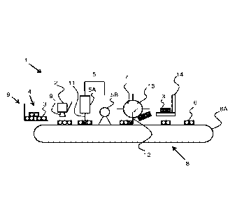
Fig. 1 shows a first schematic view of the separation apparatus.
Fig. 2 shows a second schematic view of the separation apparatus.
10 It is
noted that the figures are merely schematic representations
of a preferred embodiment of the invention, which is given here by way of
non-limiting exemplary embodiment. In the description, the same or similar
part and elements have the same or similar reference signs.
In Fig. 1 is shown a separation apparatus 1 comprising an
identifier 2 arranged to identify the particles 3 in a group of particles 4
that
have a specific property. Fig. 2 shows the separation apparatus 1 comprising
optional further elements.
The separation apparatus 1 is arranged for individual
engagement of particles. The particles may be small particles such as
shredded PE, PP or PET of different colors or different grades with a
diameter size that may range between 1-20 mm. An affinity modifier 5 is
provided that is arranged to selectively modify an affinity of the identified
particles 3 relative to that affinity of non-identified particles 6 in a group
4,
and a separator 7 is arranged to separate the particles in the group 4 based
on their difference in the affinity. The specific property that is measured by
the identifier 2 may be, e.g. a type of material, weight, color, shape and/or
size.
The sensor separation apparatus 1 in the example further
comprise a layerizer 8 arranged to bring the group of particles 4 in layer,
and preferably provides the particles 4 in the layer with a known constant
CA 02968810 2017-05-24
WO 2016/089209 PCT/NL2015/050841
11
spatial relation in the layer between the identifier 2 and the affinity
modifier 5. Worded differently, the particles 4 are by the layerizer 8
provided such that the travel time from the identifier 2 and the affinity
modifier 5 is known. This allows operation of the identifier 2 and the
affinity
modifier 5 to be synchronized.
The layerizer 8 in this embodiment comprises a conveyor belt
surface 8A on which the particles are deposited in a planar layer. The
conveyor belt surface 8A preferably has a high-friction surface, for example
comprising synthetic and/or natural rubber. As shown in Fig.1 the group
particles 4 are being fed onto the conveyor belt surface 8A by a feeder 9. The
group particles 4 may be fed onto the conveyor belt as a continuous curtain
of particles or as sections with a predetermined distance. Optionally, the
group particles 4 first passes magnetic scrap remover 15 for removing
particles in the particle feed having magnetic properties. The magnetic
scrap remover may comprise a magnet 20 for attracting particles having
magnetic properties, like particles comprising ferromagnetic metal.
Particles comprising ferromagnetic metal may comprise such ferromagnetic
metal in a pure form or in a compound, like a salt or other.
The identifier 2 is in Fig. 1 embodied as an optical sensor 10
wherein it is positioned above the layerizer 7 to identify the group particles
4 that have a specific property. For example, the identifier 2 is arranged to
identify the color of the particles 4 in a stream of clear and in particular
translucent particles. The identifier 2 is also arranged to identify a
specific
type of PP via a marker provided in the PP material. Furthermore, the
identifier 2 is arranged to identify the position of the particles on the
conveyor belt surface 8A.
After the particles 4 have passed along the identifier 2, the
affinity modifier 5 modifies the affinity of the identified particles 3 by
applying affinity modifying particles 11 to the identified particles 3. The
modifying particles 11 is, for example discharged from above the conveyor
CA 02968810 2017-05-24
WO 2016/089209 PCT/NL2015/050841
12
belt surface 8A such that the affinity modifying particles 11 form a coating
surface layer onto the identified particles 3. The affinity modifying
particles
11 are preferably discharged with a component of their velocity parallel to
the motion of the conveyor belt surface 8A. In this way, it may be avoided
that identified particles 3 are missed by the particles by time of flight
effects
related to variations in the height of the identified particles above the
conveyor belt surface 8A.
The affinity modifying particles 11 may in Fig. 1 be liquid
droplets and/or powder particles wherein the liquid droplets is in this
example is water to moisturize the identified particles to form a moisture
bridge between the identified particles 3 and the separator 7. The water
may be provided with a minor amount of additives to improve the electrical
conductivity. A reason for this is that some printers require the liquid to be
disposed to have a certain electrical conductivity for properly discharging
the liquid. This applies not only to ink, but also to water in case water is
to
be discharged by the printer. Optionally, it also possible that after the
identified particles 3 have been moisturized by liquid droplets, a second
modifier 5B or the same modifier 5A discharges a second material,
preferably powder particles. The powder particles in Fig.1 may be magnetic
powder particles, e.g. industrial ferrosilicon wherein they are preferably
spherically shaped such that the identified particles 3 may be engaged
individually and/or lifted by the separator 7.
Typically, more than one ferrosilicon particle is discharged per
identified particle 3. Preferably, a significant amount of ferrosilicon
particles is discharged per identified particle 3. In particular, the amount
of
ferrosilicon particles to be discharged is at least 1% and preferably more
than 4% of the mass of an identified particle 3. For preventing any powder
particles freely moving over the conveyor belt surface 8A, the conveyor belt
surface 8A may comprise grooves oriented substantially perpendicular to a
direction of movement of the conveyor belt surface 8A. Preferably, the
CA 02968810 2017-05-24
WO 2016/089209 PCT/NL2015/050841
13
grooves are less than one millimeter. Preferably, the particles are
discharged with a speed component perpendicular to the conveyor belt
surface 8A of less than 1 m/s. In addition, a speed component parallel to the
conveyor belt surface 8A is tuned to the velocity of the belt surface 8A.
The affinity modifier 5 is in Fig. 1 embodied as a printer head 5A
and/or a powder spray, e.g. Ferrosilicon spray 5B. With the affinity modifier
5 comprising a printer head 5 A for distributing water or another liquid for
moisturizing the liquid droplets, the printer head 5 A is arranged for
providing droplets smaller than 100 micron, preferably 30 to 50 micron. The
droplets are preferably provided at a resolution of at least 100 droplets per
inch - or 39 to 40 droplets per centimetre. At this resolution, it is possible
to
deposit liquid only on identified particles 3. Additionally to this, powder
particles may be discharged on either identified particles 3 only or on all
particles. On identified particles 3, powder particles are bound by the liquid
on the identified particles 3. Powder particles on other particles 6 may be
removed, for example by means of blowing or a magnetic field.
Alternatively, in an embodiment in which liquid as well as powder particles
are discharged, liquid is deposited at all particles 4 on the conveyor belt
and
the powder particles are only discharged on the identified particles 3.
If identified particles are moisturized, this may be done in a
blanket fashion, deploying a blanket or substantially continuous film of
liquid on either all particles 4 or identified particles 3. Alternatively,
liquid
is discharged on specific areas. This may for example be established by
depositing the liquid in lines. These lines may be parallel to the motion of
the conveyor belt, perpendicular to the motion of the conveyor belt or under
an angle relative to the motion of the conveyor belt.
In certain embodiments, it may be desired to pretreat the
particles 4 for improving adherence between affinity modifying particles and
the group particles 4. To this purpose, a pre-treatment module 21 (Fig. 2) is
provided for pretreating the group particles 4. If the affinity modifying
CA 02968810 2017-05-24
WO 2016/089209 PCT/NL2015/050841
14
particles comprise water, it may be preferred to improve hydrophilic
properties of the group particles 4. In one specific embodiment, a very thin
layer (1 to 10 nanometers) of calcium carbonate is applied to the group
particles. Such layer of calcium carbonate may be applied by exposing the
group particles to water having a sufficiently high hardness (measured, for
example, in German degrees) at a temperature of at least 80 degrees
centigrade. Exposure may be provided by means of spraying or submersion.
Submersion is preferably done for at least 30 seconds, in water of sufficient
hardness, at a temperature of at least 80 degrees. Alternatively or
additionally, a coating of for example hexamethyklisilazane and/or other
hydrophobic substances may be provided as a coating for the group particles
4. The hydrophilic coating may be applied on all particles or on identified
particles 3 only.
In a region around the ferrosilicon spray 5B - or other discharge
unit for discharging particles having magnetic properties - a weak magnetic
field may be applied. The field lines of the magnetic field are provided
substantially parallel to the direction of movement of the layerizer 8 and the
conveyor belt surface 8A in particular. The intensity of the magnetic field
preferably ranges from 0.01 Tesla to 0.05 Tesla. As an effect of the magnetic
field, rolling of the powder particles on the conveyor belt surface 8A as a
result of damping by magnetic hysteresis is suppressed. This is because the
magnetization of a rolling particle in a unidirectional field creates a loss
of
mechanical energy into heat. Furthermore, the applied weak magnetic field
also has the effect to deposit the powder particles onto the wetted particles
arranged in short strings for example, three powder particles in a row. This
is favorable for the later magnetic extraction of the scrap particles and
allows a reduced use of magnetic powder.
The separator 7 has a contact surface 12 onto which identified
particles 3 are affixed thereon such that they can be separated from the
group particles 4. The separator 7 individually engages particles for
CA 02968810 2017-05-24
WO 2016/089209
PCT/NL2015/050841
separation. Preferably, the separator 7 is a mechanical pick up device which
contact surface 12 contacts the group of particles 4 for picking up the
identified particles 3. As shown in Fig. 1 the separator 7 is embodied as a
drum 13 having a rotating surface transverse to the conveying direction.
5 Worded differently, the axis of rotation of the drum 13 is perpendicular
to
the conveying direction. The contact surface 12 of the drum 13 is in this
example coated with a hydrophilic fibrous material such that the identified
moisturized particles may be affixed thereon.
Further, it is also possible that the separator 7 is a magnet or that
10 its contact surface 12 is a magnet, has magnetic properties, or at least
is
coated with a magnetizable layer to separate the identified particles 3 which
have been coated with magnetic powder. In addition, if the separator 7 is a
magnet or its contact surface 12 is a magnet, or at least is coated with a
magnetizable layer, the separator may be used to recover particles having
15 magnetic properties that may have been discharged upstream of the
conveyor belt surface 8A. This may be particles that are adhered to
identified particles 3 and/or particles not adhered to identified particles 3,
but present on the conveyor belt surface 8A and/or present on non-identified
particles 6 not having been provided with liquid. The particles thus
recovered are fed back to a reservoir 17 (Fig. 2), allowing for reuse of the
particles. Before reuse, the particles may be de-magnetized by means of a
de-magnetizer 18 (Fig. 2) and/or dried, for example in a fluidized bed 19
(Fig. 2). It is noted in other embodiments, the order of the reservoir 17, the
de-magnetizer 18 and the fluidized bed 19 may be different.
Further, in Fig. 1 and Fig. 2 is shown that a second conveyor 14
may be provided to convey the identified particles 3 away from the group
particles 4 after the identified particles 3 have been separated.
As for the purpose of this disclosure, it is pointed out that
technical features which have been described may be susceptible of
functional generalization. It is further pointed out that ¨ insofar as not
CA 02968810 2017-05-24
WO 2016/089209
PCT/NL2015/050841
16
explicitly mentioned¨ such technical features can be considered separately
from the context of the given exemplary embodiment, and can further be
considered separately from the technical features with which they cooperate
in the context of the example.
It is pointed out that the invention is not limited to the exemplary
embodiments represented here, and that many variations are possible. For
example, the identifier may also be an identifier station comprising multiple
identifiers arranged in a row or the separation apparatus may comprise
multiple identifiers stations, preferably also arranged in a row. There may
also be an affinity modifier station or a separator station.
Further, it is noted that the separator and the affinity modifier
may be accommodated in a single device wherein modifying the affinity of
identified particles and separation may be single action and may take place
at the same time at a same position.
It is further noted that multiple separation apparatus may be
placed in one go, e.g. above a conveyor, such that multiple different
particles
may be separated from a single stream of particles.
These and other embodiments will be apparent to the person
skilled in the art and are considered to lie within the scope of the invention
as formulated by the following claims