Note : Les descriptions sont présentées dans la langue officielle dans laquelle elles ont été soumises.
1
DRILL BIT BUTTON INSERT AND DRILL BIT
TECHNICAL FIELD
[0001]
The present invention relates to a drill bit button insert that is attached to
a
button inserts mounted in a drill bit and that performs a drilling, and to the
drill bit in
which such a drill bit button insert is attached to the button inserts mounted
in the drill
bit.
BACKGROUND ART
[0002]
As a drill bit button insert that is attached to a button inserts mounted in a
drill
bit and that performs a drilling, there is disclosed a drill bit button insert
in which an
abrasive layer formed of a sintered body of polycrystalline diamond which is
harder than
a tip body is coated on the button insert working/cutting surface of the tip
body formed
of a cemented carbide. Here, in Patent Documents 1 to 5, drill bit button
inserts formed
of an abrasive layer as a multilayer structure are mainly proposed for
relieving stress in
the polycrystalline diamond sintered body. The multilayer structure has a
slope so that
hardness is decreased and toughness is increased from the outermost layer on
the surface
CA 2968940 2021-12-20
CA 02968940 2017-05-25
2
of the abrasive layer toward the tip body side.
[0003]
Generally, the outermost layer of such an abrasive layer of the multilayer
structure is a polycrystalline diamond sintered body of a composition sintered
by adding
Co or the like as a metal binder (metal catalyst) to diamond particles. In
addition, in an
inner layer, the content of diamond is decreased and metal carbide such as WC
is added
instead, so that the toughness is enhanced, while maintaining higher hardness
than the tip
body. It is proposed that the inner layer has a further multilayer structure,
and as closed
to the inner layer, the diamond content is decreased and the WC content is
increased to
give the slope in hardness and toughness.
CITATION LIST
PATENT LITERATURE
[0004]
[Patent Document 1] United States Patent No. 4694918
[Patent Document 2] United States Patent No. 8573330
[Patent Document 3] United States Patent No. 8695733
[Patent Document 4] United States Patent No. 8292006
[Patent Document 5] Japanese Patent Publication No. 4676700
DISCLOSURE OF INVENTION
TECHNICAL PROBLEM
[0005]
Incidentally, in a drilling operation by a drill bit to which such a drill bit
button
insert is attached, for example, tens or more of drilling holes with a depth
of several
CA 02968940 2017-05-25
3
meters are drilled on one rock surface, and explosives are charged in these
drilling holes
to be blasted so that large drilling holes are formed. Accordingly, in order
to improve
the efficiency of the drilling operation, when ten or more drilling holes on
one surface are
drilled, a drill bit with a long life which does not require exchange in the
middle is
required.
[0006]
However, in the drill bit button insert having an abrasive layer of a
multilayer
structure as described above, if the drill bit button insert suddenly hits an
extremely hard
ultra-hard rock or the like among the rocks during drilling, and damage or
chipping
occurs in a polycrystalline diamond sintered body layer of the outermost
layer, the
hardness of the inside of the abrasive layer is decreased and the relatively
soft layer is
exposed. If the inside of the abrasive layer is exposed in that manner, wear
rapidly
progresses from the exposed portion and the wear reaches a tip body, and thus
drilling
becomes impossible and the life of the drill bit is expended.
[0007]
The present invention is made under such circumstances, and provides a drill
bit
button insert capable of maintaining drilling performance without causing wear
to
immediately reach a tip body even if damage or chipping occurs in the outer
layer at the
time of drilling. In addition, an object is to provide a drill bit having a
long life to
which such a drill bit button insert is attached.
SOLUTION TO PROBLEM
[0008]
In order to solve the above problem and to achieve such an object, a drill bit
button insert that is one embodiment of the present invention, is attached to
a button
= CA 02968940 2017-05-25
4
inserts mounted in a drill bit, and performs a drilling, includes a tip body
and an abrasive
layer formed of a diamond sintered body harder than the tip body coated at
least at the
button insert working/cutting surface of the tip body, in which the abrasive
layer has at
least two high hardness layers and a low hardness layer having a hardness
lower than that
of the high hardness layer disposed between the high hardness layers from the
surface
side of the abrasive layer toward the tip body side.
[0009]
In the drill bit button insert configured in this manner, since the abrasive
layer
formed of the diamond sintered body coated at the button insert
working/cutting surface
of the tip body has at least two high hardness layers and the low hardness
layer having a
hardness lower than that of the high hardness layer disposed between these
high hardness
layers from the surface side of the abrasive layer toward the tip body side,
that is, from
the outer layer side toward the inner side of the abrasive layer, even if
damage and
chipping occur in the high hardness layer on the outer layer side during the
drilling to
expose the inside, and the low hardness layer of the inner side wears out from
this
exposed portion, the progress of wear can be suppressed by the high hardness
layer on
the tip body side located at the inner side of the low hardness layer.
[0010]
Therefore, according to the drill bit button insert of the above-described
configuration, it is possible to prevent the wear generated in the abrasive
layer from
rapidly progressing to reach the tip body, and to maintain the drilling
performance of the
drill bit button insert by the high hardness layer of the inner side.
Accordingly, in the
drill bit of the present invention in which such a drill bit button insert is
attached to
button inserts mounted in a drill bit, the life thereof can be extended so
that it is not
required to replace the drill bit button insert while drilling a plurality of
drilling holes and
CA 02968940 2017-05-25
1
it is possible to promote efficiency of the drilling operation.
[0011]
In addition, in the abrasive layer, a plurality of high hardness layers and
low
hardness layers are alternately disposed from the surface side of the abrasive
layer toward
5 the tip body side. Therefore, even for the high hardness layer of the
inner side, it is
possible to relieve the stress by the low hardness layer, which is disposed on
the further
inner side of the high hardness layer and has a hardness lower and a toughness
higher
than that of the high hardness layer. Furthermore, if three or more high
hardness layers
are alternately disposed with the low hardness layer, it is possible to
prolong the life of
the drill bit button insert according to the number of layers of the high
hardness layer.
[0012]
Here, it is desirable that the thickness of the high hardness layer is set to
be in a
range of 1/2 or more of the thickness of the low hardness layer, and of the
thickness of
the low hardness layer or less. The thickness of the high hardness layer is
set to be 1/2
or more of the thickness of the low hardness layer so that it is possible to
cause the
thickness of the low hardness layer to be relatively twice or less of that of
the high
hardness layer. Therefore, when the damage or the like occurs in the high
hardness
layer of the outer layer, it is possible to ensure the drilling length and
time until the wear
reaches the high hardness layer of the inner side. However, if the thickness
of the high
hardness layer is thicker than that of the low hardness layer, there is a
possibility that the
stress of the high hardness layer cannot be sufficiently relieved.
[0013]
In addition, specifically, it is desirable that each of the thickness of high
hardness layer and the thickness of the low hardness layer is 150 gm or more
at the
thinnest portion, and 800 gm or less at the thickest portion, respectively. In
both the
CA 02968940 2017-05-25
6
high hardness layer and the low hardness layer, in a case where the thickness
of the
thinnest portion is less than 150 gm, it is difficult to uniformly form the
layer so that
there is a possibility that sufficient wear resistance cannot be obtained. On
the other
hand, in a case where the thickness of the thickest portion exceeds 800 gm,
when the
high hardness layer of the outer layer is damaged at this portion and the low
hardness
layer of the inner side thereof wears out, the surface of the abrasive layer
is largely
peeled off and the shape of the button insert working/cutting surface of the
drill bit button
insert becomes distorted so that there is a possibility that desired drilling
performance
cannot be obtained.
[0014]
As described above, the high hardness layer may be a layer of a
polycrystalline
diamond sintered body sintered by adding a metal binder (metal catalyst) such
as Co to
diamond particles, and the low hardness layer may be a layer formed of a
diamond
sintered body to which particles such as metal carbide or metal nitride are
added by
decreasing the content of diamond particles. In addition, in both the high
hardness layer
and the low hardness layer, as the diamond sintered body layer sintered by
containing
diamond particles, metal binder, and additive particles such as metal carbide,
metal
nitride, metal carbonitride and the like, the hardness may be decreased by
adjusting the
content and particle diameter of the diamond particles, and the content, type,
composition
ratio and the like of the additive particles such as metal binder and metal
carbide in the
high hardness layer and the low hardness layer.
[0015]
Furthermore, by adjusting the hardness in this manner, an intermediate layer
having a hardness lower than that of the high hardness layer and a hardness
higher than
that of the low hardness layer may be disposed from the surface side of the
abrasive layer
7
toward the tip body side between the high hardness layer and the low hardness
layer.
By providing such an intermediate layer, stress relief of the high hardness
layer on the
outer layer side is maintained, and even when the damage or the like occurs in
the high
hardness layer, it is possible to ensure the drilling performance until the
wear reaches
the low hardness layer.
[0015a]
Accordingly, in one aspect, the present invention resides in a drill bit
button
insert that is attached to a button inserts mounted in a drill bit and
performs a drilling,
comprising: a tip body; and an abrasive layer formed of a diamond sintered
body harder
than the tip body coated at least at a button insert working surface of the
tip body,
wherein the abrasive layer has two or more high hardness layers and a low
hardness
layer having a hardness lower than that of the two or more high hardness
layers
disposed between the two or more high hardness layers, from a surface side of
the
abrasive layer toward a tip body side, and wherein an intermediate layer
having a
hardness lower than that of the two or more high hardness layers and a
hardness higher
than that of the low hardness layer is disposed between one of the two or more
high
hardness layers in the surface side of the abrasive layer and the low hardness
layer, from
the surface side of the abrasive layer toward the tip body side.
ADVANTAGEOUS EFFECTS OF INVENTION
[0016]
As described above, according to the present invention, even if the drill bit
button insert suddenly hits an extremely hard ultra-hard rock or the like
among the rocks
during drilling, and damage or chipping occurs in the high hardness layer of
the outer
layer of the abrasive layer and the wear progresses from the exposed portion
to the low
CA 2968940 2021-12-20
7a
hardness layer of the inner side, it is possible to prevent the wear from
reaching the tip
body at once and to maintain the drilling performance so that it is possible
to extend the
life of the drill bit and to achieve the efficient drilling operation.
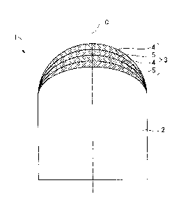
BRIEF DESCRIPTION OF DRAWINGS
[0017]
FIG. 1 is a cross-sectional view showing an embodiment of a drill bit button
insert of the present invention.
FIG. 2 is a cross-sectional view showing an embodiment of a drill bit of the
present invention in which the drill bit button insert of the embodiment shown
in FIG. 1
is attached to a button inserts mounted in a drill bit.
BEST MODE FOR CARRYING OUT THE INVENTION
CA 2968940 2021-12-20
CA 02968940 2017-05-25
8
[0018]
FIG. 1 is a cross-sectional view showing an embodiment of a drill bit button
insert 1 of the present invention. FIG. 2 is a cross-sectional view showing an
embodiment of a drill bit of the present invention to which the drill bit
button insert 1 of
the embodiment is attached. The drill bit button insert 1 of the present
embodiment is
provided with a tip body 2 formed of a hard material such as a cemented
carbide or the
like and an abrasive layer 3 formed of a diamond sintered body harder than the
tip body 2
and coated on a button insert working/cutting surface of the tip body 2 (upper
portion in
FIG. 1).
[0019]
In the tip body 2, a rear end portion thereof (lower portion in FIG. 1) has a
columnar shape centered on a tip center line C, the button insert
working/cutting surface
has a hemispherical shape having a center on the tip center line C at a radius
equal to the
radius of the cylinder formed by the rear end portion, and an outer diameter
from the tip
center line C gradually decreases toward the tip end side. That is, the drill
bit button
insert 1 of the present embodiment is a button tip.
[0020]
The drill bit in which the drill bit button insert 1 is attached to the button
inserts
mounted in the drill bit has a bit body 11 formed of steel or the like and
having a
substantially bottomed cylindrical shape centered on an axis 0 as shown in
FIG. 2, and
the bottomed portion thereof is the button inserts mounted in the drill bit
(upper portion
in FIG. 2) to which the drill bit button insert 1 is attached.
In addition, a female threaded portion 12 is formed on the inner periphery of
the
cylindrical rear end portion (lower portion in FIG. 2), and a drill rod
connected to a
drilling device is screwed into the female threaded portion 12 to transmit a
striking force
CA 02968940 2017-05-25
9
and a thrust toward the tip end side in the direction of the axis 0 and a
rotating force
around the axis 0. In this manner, the rock is crushed by the drill bit button
insert 1 to
form a drilling hole.
[0021]
The button inserts mounted in the drill bit of the bit body 11 has a slightly
larger
outer diameter than the rear end portion, a plurality of discharge grooves 13
extending in
parallel with the axis 0 are formed on the outer periphery of the button
inserts mounted
in the drill bit with an interval in the circumferential direction, and the
crushed chips
generated by the rock crushing by the drill bit button insert 1 is discharged
to the rear end
side through the discharge groove 13. In addition, a blow hole 14 is formed
along the
axis 0 from the bottom surface of the female threaded portion 12 of the bit
body 11
having a bottom. The blow hole 14 diagonally branches at the button inserts
mounted
in the drill bit of the bit body 11, opens to a tip end surface of the bit
body 11, and ejects
a fluid such as compressed air supplied via the drill rod to promote discharge
of crushed
chips.
[0022]
Furthermore, the tip end surface of the bit body ills provided with a circular
face surface 15 centered on the axis 0 perpendicular to the axis 0 on the
inner periphery
side, and a truncated cone-shaped gauge surface 16 which is located on the
outer
periphery of the face surface 15 and which faces the rear end side toward the
outer
peripheral side. The blow hole 14 opens to the face surface 15 and the tip end
of the
discharge groove 13 opens to the gauge surface 16.
[0023]
On the face surface 15 and the gauge face 16, a plurality of attachment holes
17
having a circular cross section are formed so as to avoid opening portions of
the blow
CA 02968940 2017-05-25
A
hole 14 and the discharge groove 13, respectively. In the drill bit button
insert 1, the
cylindrical rear end portion thereof is fixed by being tightly fitted or
brazed to the
attachment hole 17 by press fitting, shrink fitting or the like, and is
attached so that the
tip center line C is perpendicular to the face surface 15 and the gauge
surface 16.
5 [0024]
In the drill bit button insert 1 attached to the button inserts mounted in the
drill
bit in this manner, the abrasive layer 3 coated on the button insert
working/cutting
surface has at least two high hardness layers 4 and a low hardness layer 5
having a
hardness lower than that of the high hardness layer 4 disposed between these
high
10 hardness layers 4 from a surface side of the abrasive layer 3 toward the
tip body 2 side.
Furthermore, in the present embodiment, the low hardness layer 5 is disposed
between
the high hardness layer 4 on the tip body 2 side and the tip body 2, and a
plurality of two
high hardness layers 4 and two low hardness layers 5 are alternately disposed
in this
order from the surface of the abrasive layer 3 toward the surface of the tip
body 2.
[0025]
Among these, the high hardness layer 4 is a layer of a polycrystalline diamond
sintered body sintered by only adding a metal binder (metal catalyst) such as
Co, Ni or Fe
- Ni alloy to diamond particles. On the other hand, the low hardness layer 5
reduces the
content of diamond particles with respect to the high hardness layer 4, and is
a sintered
body layer sintered by adding metal carbide particles such as WC, TaC and TiC,
metal
nitride particles such as TiN and cBN, metal carbonitride particles such as
TiCN, and a
metal binder as described above. In this manner, the hardness of the low
hardness layer
5 can be reduced than that of the high hardness layer 4. In a case of being
prepared in
this manner, the Vickers hardness of the high hardness layer 4 is in a range
of
approximately 2500 to 4000, and the Vickers hardness of the low hardness layer
5 is in a
CA 02968940 2017-05-25
=
11
range of approximately 1500 to 2500.
[0026]
Furthermore, both the high hardness layer 4 and the low hardness layer 5 may
be
sintered body layers sintered by containing diamond particles, the above-
described metal
binder and additive particles such as metal carbide, metal nitride, metal
carbonitride and
the like. Among these, in the low hardness layer 5, the content and particle
diameter of
the diamond particles are decreased and the content, type, composition ratio,
and the like
of the additive particles such as metal carbide are adjusted so that the
hardness can be
reduced than that of the high hardness layer 4. Sintering of the drill bit
button insert 1
in which such an abrasive layer 3 is coated on the button insert
working/cutting surface
of the tip body 2 is basically performed in a diamond stable region and, for
example, is
possible by known sintering methods as described in Patent Documents 1 to 5.
[0027]
In the drill bit button insert 1 having such a configuration and the drill bit
in
.. which the drill bit button insert 1 is attached to the button inserts
mounted in the drill bit,
in a case where the drill bit button insert 1 suddenly hits extremely ultra-
hard rock or the
like among the rocks during the drilling, the damage or chipping occurs in the
outermost
first high hardness layer 4 among the abrasive layers 3 coated on at least the
button insert
working/cutting surface of the tip body 2 to expose the inside of the abrasive
layer 3. In
this manner, the low hardness layer 5 of the inner side is worn out, but the
second high
hardness layer 4 having a hardness higher than that of the low hardness layer
5 is
disposed on the further inner side of the low hardness layer 5. Therefore, it
can be
suppressed by the second high hardness layer 4 that the wear rapidly
progresses until
reaching the tip body 2.
[0028]
CA 02968940 2017-05-25
12
Accordingly, even after the low hardness layer 5 between the first and second
high hardness layers 4 wears out due to the progress of the wear, the drilling
can be
continued by the tip body 2 side of the abrasive layer 3, that is, the second
high hardness
layer 4 of the inner side so that the drilling performance can be maintained.
Therefore,
.. according to the drill bit in which such a drill bit button insert 1 is
attached to the button
inserts mounted in the drill bit, the life of the drill bit can be prolonged.
Even in a case
of forming tens or more of drilling holes of several meters on the one surface
of the rock,
it is not required to exchange drilling bits in the middle and it is possible
to perform an
efficient drilling operation.
[0029]
In addition, between these first and second high hardness layers 4, since the
low
hardness layer 5 having a hardness lower, but a toughness higher than that of
the high
hardness layer 4 is interposed, even in a case where the high hardness layer 4
is
specifically a polycrystalline diamond sintered body sintered by adding only
the metal
.. binder to the diamond particles, the residual stress generated in the high
hardness layer 4
can be relieved. In addition, in the present embodiment, a plurality of layers
(two
layers) of the high hardness layer 4 and the low hardness layer 5 are
alternately disposed
from the surface side of the abrasive layer 3 toward the tip body 2 side.
Therefore, the
stress of the second high hardness layer 4 of the inner side can be relieved
by the low
hardness layer 5 interposed between the inner sides thereof, that is, the
second high
hardness layer 4 and the tip body 2.
[0030]
In the embodiment, although the high hardness layer 4 and the low hardness
layer 5 of two layers are alternately disposed from the surface side of the
abrasive layer 3
toward the tip body 2 side in this manner, in the abrasive layer 3, at least
two high
CA 02968940 2017-05-25
13
hardness layers 4 and one low hardness layer 5 disposed therebetween may be
provided.
That is, the second high hardness layer 4 closest to the tip body 2 may be
directly coated
on the button insert working/cutting surface of the tip body 2. In addition,
three or more
high hardness layers 4 may be alternately disposed with the low hardness layer
5
interposed therebetween, for example, it may be even numbers of the abrasive
layers 3 in
which the same number of high hardness layers 4 and low hardness layers 5 are
alternately stacked, and it may be odd numbers of the abrasive layers 3 in
which the
outermost layer and the innermost layer are the high hardness layers 4 and the
low
hardness layers 5 are disposed between each of the high hardness layers 4. In
the
abrasive layer 3, two to six high hardness layers 4 and low hardness layers 5
may be
alternately disposed from the surface side of the abrasive layer 3 toward the
tip body 2
side. The total number of layers of the high hardness layer and the low
hardness layer
may be 4 layers or more and 12 layers or less.
[0031]
Furthermore, an intermediate layer having a hardness lower than that of the
high
hardness layer 4 and higher than that of the low hardness layer 5 may be
disposed
between the high hardness layer 4 and the low hardness layer 5 from the
surface side of
the abrasive layer 3 toward the tip body 2 side. For example, in a case where
the high
hardness layer 4 is a polycrystalline diamond sintered body layer sintered by
adding only
a metal binder to diamond particles, the content and particle diameter of the
diamond
particles, and the content, type, composition ratio, or the like of the
additive particles
such as metal binder and metal carbide are adjusted, so that the intermediate
layer having
a hardness higher than that of the low hardness layer 5 and lower than that of
the high
hardness layer 4 may be disposed between the high hardness layer 4 and the low
hardness
layer 5.
CA 02968940 2017-05-25
=
14
[0032]
Since in such an intermediate layer, the hardness can be decreased and the
toughness can be increased for the high hardness layer 4 on the outer layer
side, the stress
of the high hardness layer 4 can be relieved to some extent. On the other
hand, since
the hardness is high for the low hardness layer 5 on the inner layer side,
when the
damage or chipping occurs in the high hardness layer 4, the drilling
performance can be
maintained until the wear reaches the low hardness layer 5. As a result, it is
possible to
extend the life of the drill bit button insert 1. The intermediate layer
itself may be
formed of a plurality of layers whose hardness gradually decreases from the
surface side
of the abrasive layer 3 toward the tip body 2, that is, from the outer layer
side toward the
inner layer side.
[0033]
Here, it is desirable that the thickness of each high hardness layer 4 is in a
range
of 1/2 or more of the thickness of the low hardness layer 5 and of the
thickness of the low
hardness layer 5 or less. If the thickness of the high hardness layer 4 is not
larger than
the thickness of the low hardness layer 5, this low hardness layer 5 is
sufficient to relieve
the stress of the high hardness layer 4. In addition, if the thickness of the
high hardness
layer 4 is 1/2 or more of the thickness of the low hardness layer 5, since the
thickness of
the low hardness layer 5 is relatively twice or less of the thickness of the
high hardness
layer 4, the stress relief of the high hardness layer 4 can be more reliably
achieved.
Furthermore, as the thickness of the low hardness layer 5 is obtained in this
manner, it is
possible to ensure a drilling length and time until the wear reaches the high
hardness
layer 4 on the inner side of the low hardness layer 5 and the tip body 2 due
to the low
hardness layer 5 harder than the tip body 2, even at low hardness.
[0034]
CA 02968940 2017-05-25
More specifically, it is desirable that the thickness of each high hardness
layer 4
and the thickness of the low hardness layer 5 are 150 i.tm or more at the
thinnest portion
and 800 gm or less at the thickest portion, respectively. In each of the high
hardness
layer 4 and the low hardness layer 5, if the thickness of the thinnest portion
is less than
5 .. 150 gm, it is difficult to cause the thickness uniform in a case where
the high hardness
layer 4 and the low hardness layer 5 are sintered body layers containing
diamond
particles as described above so that there is a possibility that sufficient
wear resistance
cannot be obtained. In addition, if the thickness of the thickest portion
exceeds 800 gm,
when the high hardness layer 4 is damaged in the thickest portion and the low
hardness
10 .. layer 5 wears out, the surface of the abrasive layer 3 largely peels off
and the shape of the
button insert working/cutting surface of the drill bit button insert 1 is
distorted so that
there is a possibility that desired drilling performance cannot be obtained.
This is the
same as the intermediate layer.
[0035]
15 It is desirable that the total thickness of the abrasive layer 3 is in
the range of
450 gm to 2500 gm. If the thickness of the entire abrasive layer 3 is less
than 450 gm,
even in a case where the abrasive layer 3 is formed by the two high hardness
layers 4 and
the one low hardness layer 5 having the smallest number of layers, a portion
where the
thickness of the thinnest portion is less than 150 gm occurs in any layer as
described
.. above, and the absolute thickness of the abrasive layer 3 is too thin and
wears out
immediately so that there is a possibility that it is not possible to form the
drilling hole
with a necessary drilling length. On the other hand, if the thickness of the
abrasive
layer 3 exceeds 2500 gm, in a case where the high hardness layer 4 and the low
hardness
layer 5 are the diamond sintered body layers, even if the stress is relieved
due to the low
.. hardness layer 5, there is a possibility that cracking is likely to occur
in the entire drill bit
CA 02968940 2017-05-25
16
button insert 1 due to residual stress.
[0036]
In the drill bit button insert 1 of the present embodiment, the case where the
present invention is applied to a button type drill bit button insert in which
the button
insert working/cutting surface of the tip body 2 has a hemispherical shape is
described
above. However, it is possible to apply the present invention to a so-called
ballistic type
drill bit button insert in which the button insert working/cutting surface of
the tip body
has a shell shape, and to a so-called spike type drill bit button insert in
which the rear end
side of the button insert working/cutting surface has a conical surface shape
and
decreases in diameter toward the tip end side, and a tip end has a spherical
shape with a
smaller radius than the cylindrical rear end portion of the tip body.
EXAMPLES
[0037]
Next, the effect of the drill bit button insert and the drill bit of the
present
invention will be demonstrated with reference to examples. In the example,
five types
of button type drill bit button inserts with 11 mm diameter of a hemispherical
formed by
a button insert working/cutting surface were manufactured. The drill bit
button insert
was coated with varying particle diameters and volume contents of diamond
particles and
additive particles such as metal carbide in the high hardness layer and the
low hardness
layer of the abrasive layer (in the intermediate layer in Example 3),
compositions and
addition ratios of metal binder, and number of layers and thickness of each
layer. These
were designated as Examples 1 to 5. Similarly to the methods described in
Patent
Documents 1 to 5, all of the sintering of the examples was performed by using
an
ultra-high pressure and high temperature generator, at a pressure of 5.8 GPa,
a
CA 02968940 2017-05-25
=
17
temperature of 1500 C, and a sintering time of 10 minutes which were a stable
region of
diamond.
[0038]
In Example 1, a high hardness layer was formed to a thickness of 200 gm with a
mixture containing 30 vol% of diamond particles having a particle diameter of
2 to 4 gm,
70 vol% of diamond particles having a particle diameter of 20 to 40 gm and 15
vol%
(content ratio with respect to the entire layer containing particles,
hereinafter, the same as
above.) of metal binder of Ni: 100 wt% without containing additive particles.
In
addition, a low hardness layer was formed to a thickness of 400 pm with a
mixture
containing 60 vol% of diamond particles having a particle diameter of 4 to 6
gm, 40
vol% of TaC particles having a particle diameter of 0.5 to 2 gm as additive
particles, and
10 vol% of a metallic binder of Co: 100 wt%. A button insert working/cutting
surface
was coated with an abrasive layer in which these layers were alternately
disposed in
respective three layers from a surface side toward a tip body side.
[0039]
In Example 2, a high hardness layer was formed to a thickness of 150 pm with a
mixture containing 100 vol% of diamond particles having a particle diameter of
10 to 20
gm and 10 vol% of metal binder of Co: 100 wt% without containing additive
particles.
In addition, a low hardness layer was formed to a thickness of 200 gm with a
mixture
containing 50 vol% of diamond particles having a particle diameter of 4 to 6
gm, 50
vol% of WC particles having a particle diameter of 0.5 to 2 p.m as additive
particles, and
15 vol% of a metallic binder of Co: 100 wt%. A button insert working/cutting
surface
was coated with an abrasive layer in which these layers were alternately
disposed in
respective six layers from a surface side toward a tip body side.
[0040]
CA 02968940 2017-05-25
18
In Example 3, a high hardness layer was formed to a thickness of 200 gm with a
mixture containing 30 vol% of diamond particles having a particle diameter of
0.5 to 2
gm, 70 vol% of diamond particles having a particle diameter of 4 to 6 gm and
10 vol% of
metal binder of Co: 100 wt% without containing additive particles. An
intermediate
layer was formed to a thickness of 200 gm with a mixture containing 60 vol% of
diamond particles having a particle diameter of 4 to 6 gm, 40 vol% of WC
particles
having a particle diameter of 0.5 to 2 gm as additive particles, and 5 vol% of
a metallic
binder of Co: 100 wt%. A low hardness layer was formed to a thickness of 200
gm with
a mixture containing 20 vol% of diamond particles having a particle diameter
of 4 to 6
gm, 80 vol% of WC particles having a particle diameter of 0.5 to 2 gm as
additive
particles, and 5 vol% of a metallic binder of Co: 100 wt%. A button insert
working/cutting surface was coated with an abrasive layer in which these
layers were
alternately disposed in respective two layers from a surface side toward a tip
body side.
[0041]
In Example 4, a high hardness layer was formed to a thickness of 400 gm with a
mixture containing 65 vol% of diamond particles having a particle diameter of
15 to 30
gm, 35 vol% of TiC particles having a particle diameter of 0.5 to 1.3 gm as
additive
particles, and 15 vol% of metal binder of Co: 100 wt%. In addition, a low
hardness
layer was formed to a thickness of 800 gm with a mixture containing 30 vol% of
diamond particles having a particle diameter of 15 to 30 gm, 70 vol% of TiCN
particles
having a particle diameter of 0.5 to 2 gm as additive particles, and 10 vol%
of a metallic
binder of Co: 100 wt%. A button insert working/cutting surface was coated with
an
abrasive layer in which these layers were alternately disposed in respective
two layers
from a surface side toward a tip body side.
[0042]
CA 02968940 2017-05-25
19
In Example 5, a high hardness layer was formed to a thickness of 200 gm with a
mixture containing 80 vol% of diamond particles having a particle diameter of
6 to 12
gm, 20 vol% of WC particles having a particle diameter of 2 to 4 gm as
additive
particles, and containing 15 vol% of metal binder of Fe: 69w0/0, Ni: 31wt%. In
.. addition, a low hardness layer was formed to a thickness of 300 gm with a
mixture
containing 40 vol% of diamond particles having a particle diameter of 15 to 30
gm, 60
vol% of cBN particles having a particle diameter of 2 to 4 gm as additive
particles, and
vol% of a metallic binder of Co: 100 wt%. A button insert working/cutting
surface
was coated with an abrasive layer in which these layers were alternately
disposed in
10 respective two layers from a surface side toward a tip body side.
[0043]
On the other hand, as comparative examples to these Examples 1 to 5, four
types
of button type drill bit button inserts with 11 mm diameter of a hemisphere
formed by a
button insert working/cutting surface coated with an abrasive layer not having
a low
hardness layer between the two high hardness layers were manufactured. These
were
designated as Comparative Examples 1 to 4. Similarly to the examples, all of
the
sintering of the comparative examples was performed by using an ultra-high
pressure and
high temperature generator, at a pressure of 5.8 GPa, a temperature of 1500 C,
and a
sintering time of 10 minutes which were a stable region of diamond.
[0044]
In Comparative Example 1, a high hardness layer was formed to a thickness of
200 gm with a mixture containing 30 vol% of diamond particles having a
particle
diameter of 0.5 to 2 gm, 70 vol% of diamond particles having a particle
diameter of 4 to
6 gm and 10 vol% of metal binder of Co: 100 wt% without containing additive
particles.
In addition, an intermediate layer was formed to a thickness of 400 gm with a
mixture
CA 02968940 2017-05-25
containing 60 vol% of diamond particles having a particle diameter of 4 to 6
pm, 40
vol% of WC particles having a particle diameter of 0.5 to 2 gm as additive
particles, and
5 vol% of a metallic binder of Co: 100 wt%. Furthermore, a low hardness layer
was
formed to a thickness of 600 gm with a mixture containing 20 vol% of diamond
particles
5 having a particle diameter of 4 to 6 gm, 80 vol% of WC particles having a
particle
diameter of 0.5 to 2 gm as additive particles, and 5 vol% of a metallic binder
of Co: 100
wt%. A button insert working/cutting surface was coated with an abrasive layer
in
which these layers were disposed in only respective one layer in order from a
surface side
toward a tip body side.
10 [0045]
In Comparative Example 2, a hardness layer was coated with only one layer
having a thickness of 800 gm with a mixture containing 30 vol% of diamond
particles
having a particle diameter of 0.5 to 2 gm, 70 vol% of diamond particles having
a particle
diameter of 4 to 6 p.m and 10 vol% of metal binder of Co: 100 wt% without
containing
15 additive particles.
[0046]
In Comparative Example 3, a high hardness layer was formed to a thickness of
400 p.m with a mixture containing 30 vol% of diamond particles having a
particle
diameter of 0.5 to 2 gm, 70 vol% of diamond particles having a particle
diameter of 4 to
20 6 gm and 10 vol% of metal binder of Co: 100 wt% without containing
additive particles.
In addition, a low hardness layer was formed to a thickness of 600 gm with a
mixture
containing 60 vol% of diamond particles having a particle diameter of 4 to 6
gm, 40
vol% of WC particles having a particle diameter of 0.5 to 2 gm as additive
particles, and
5 vol% of a metallic binder of Co: 100 wt%. A button insert working/cutting
surface
was coated with an abrasive layer in which these layers were disposed in only
respective
CA 02968940 2017-05-25
21
one layer in order from a surface side toward a tip body side.
[0047]
In Comparative Example 4, a high hardness layer was formed to a thickness of
400 gm with a mixture containing 30 vol% of diamond particles having a
particle
diameter of 0.5 to 2 pm, 70 vol% of diamond particles having a particle
diameter of 4 to
6 lam and 10 vol% of metal binder of Co: 100 wt% without containing additive
particles.
In addition, a low hardness layer was formed to a thickness of 600 gm with a
mixture
containing 20 vol% of diamond particles having a particle diameter of 4 to 6
}.un, 80
vol% of WC particles having a particle diameter of 0.5 to 2 gm as additive
particles, and
5 vol% of a metallic binder of Co: 100 wt%. A button insert working/cutting
surface
was coated with an abrasive layer in which these layers were disposed in only
respective
one layer in order from a surface side toward a tip body side.
[0048]
The drill bit button inserts (button tips) of Examples 1 to 5 and Comparative
Examples 1 to 4 manufactured in this manner were attached seven in total of
five to the
gauge surface and two to the face surface of the drill bit with a bit diameter
of 45 mm.
The drilling operation was performed to drill the drilling holes with a
drilling length of 4
m in a copper mine with an average uniaxial compressive strength of 180 MPa
including
hard rock and ultra-hard rock using these, the total drilling length (m) until
the drill bit
button insert reached the end of life was measured and the wear form of the
drill bit
button insert at the end of drilling was checked. Drilling conditions were a
drilling
device of model No. H205D manufactured by TAMROCK, a striking pressure of 160
bars, a feed pressure of 80 bars, and a rotational pressure of 55 bars. In
addition, water
was supplied from the blow hole and the water pressure was 18 bars. The
results are
shown in Table 1.
CA 02968940 2017-05-25
=
22
[0049]
[Table 1]
Total drilling length Wear form
Example 1 368 (m) Normal wear
Example 2 424 m Normal wear
Example 3 236 (m) Normal wear
Example 4 382 (m) Normal wear
Example 5 332 (m) Normal wear
Normal wear and partial
Comparative Example 1 112 (m)
chipping
Comparative Example 2 40 (m) Layer separation
Normal wear and partial
Comparative Example 3 88 (m)
chipping
Normal wear and partial
Comparative Example 4 84 (m)
chipping
[0050]
From these results, in the drill bits to which the drill bit button inserts of
Comparative Examples 1 to 4 were attached, partial chipping occurred in the
drill bit
button insert in addition to normal wear even in Comparative Example 1 having
the
longest drilling length, and the drill bits reached the end of life with a
drilling length of
approximately 1/2 of the drill bits to which the drill bit button inserts of
Examples 1 to 5
were attached. Specifically, in Comparative Example 2 in which the abrasive
layer was
one layer, the drill bits reached the end of life when 10 holes were drilled
by layer
separation, and it was not possible to form a sufficient number of drilling
holes on one
surface of the rock with one drill bit.
[0051]
On the other hand, in the drill bits to which the drill bit button inserts of
Examples 1 to 5 were attached, it is possible to form drilling holes of
approximately 60
holes even in Example 3 having the shortest total drilling length. In a case
of forming
ten or more drilling holes on one rock surface, efficient drilling was
possible without
replacing the drill bits for approximately three surfaces. Specifically, in
Example 2 in
CA 02968940 2017-05-25
v
23
which the number of layers of the high hardness layer was large, it was
possible to form
the drilling holes of 100 holes or more, and to perform an extremely efficient
drilling
operation.
[0052]
When trying to manufacture a drill bit button insert having an abrasive layer
in
which a high hardness layer and a low hardness layer are alternately stacked
in respective
two layers, with the same composition of high hardness layer and low hardness
layer as
in Example 1, with 1000 pm of the thickness of the high hardness layer, and
with 200 gm
of the thickness of the low hardness layer, the thickness of the high hardness
layer
exceeded 800 pm, the residual stress of the high hardness layer in the
abrasive layer was
high, and interlayer cracking occurred in the high hardness layer at the time
of sintering
so that the drill bit button insert could not be manufactured.
INDUSTRIAL APPLICABILITY
[0053]
As described above, according to the present invention, even if the drill bit
button insert suddenly hits an extremely hard ultra-hard rock or the like
among the rocks
during drilling, and damage or chipping occurs in the high hardness layer of
the outer
layer of the abrasive layer and the wear progresses from the exposed portion
to the low
hardness layer of the inner side, it is possible to prevent the wear from
reaching the tip
body at once and to maintain the drilling performance so that it is possible
to extend the
life of the drill bit and to achieve an efficient drilling operation.
REFERENCE SIGNS LIST
[0054]
CA 02968940 2017-05-25
. ,
. =
24
1. Drill bit button insert
2. Tip body
3. Abrasive layer
4. High hardness layer
5. Low hardness layer
11. Bit body
C. Tip center line
0. Axis of bit body 11