Note : Les descriptions sont présentées dans la langue officielle dans laquelle elles ont été soumises.
CA 02969032 21317-6
, PCT/EP2015/076930
2014223458WOUS
- 1 -
,
,Description
Superconducting device with coil devices and cooling device,
and vehicle fitted therewith
The invention relates to a superconducting apparatus comprising
at least two electrical coil devices, at least one of which is
designed as a superconducting coil device, and comprising a
cooling apparatus for cooling the coil devices with the aid of
a coolant. In addition, the invention relates to a vehicle
comprising an apparatus of this kind.
Known superconducting apparatuses can comprise one or more
superconducting coil devices. A superconducting coil device of
this kind has at least one coil winding with a superconducting
conductor material. Said coil winding may be, for example, a
coil winding of a transformer or a coil winding of a
superconducting machine, in particular a superconducting rotor
winding or a superconducting stator winding or else
superconducting rotor and stator windings which are present in
a machine together.
The superconducting apparatuses described here are apparatuses
comprising at least two electrical coil devices, either one of
which or both of which are designed as superconducting coil
devices. These two electrical coil devices may be, in
particular, firstly coils of a transformer and secondly of an
electrical machine, wherein the machine can generally be
designed as a motor or as a generator. In an apparatus of this
kind, it is possible, for example, for either only the
transformer to have a superconducting coil device or for only
the machine to have a superconducting coil device or for both
the transformer and the machine to each have at least one
superconducting coil device.
CA 02969032 2017-05-26
PCT/EP2015/076930
2014P23458W0US
- 2
A combination of this kind of a transformer and a motor in a
superordinate apparatus can be used, for example, in rail
vehicles. The coil devices of an apparatus of this kind - both
the superconducting and the normally conducting coil devices -
can then be cooled by a common cooling apparatus with the aid
of a coolant. German patent application bearing the file
reference 102014208437.7, which is not a prior publication,
describes, for example, a cooling device for at least two
components to be cooled, at least one of which comprises a
superconductor, wherein all of the components are cooled by the
same cooling medium which is guided in a closed cooling
circuit.
One disadvantage of the superconducting apparatuses known to
date comprising a plurality of coil devices is that, to date,
each of these coil devices is equipped with its own current
supplies for connection to an outer electrical circuit, this at
the same time also constituting a thermal bridge between the
coil and the outer environment for each of these coil devices.
Thermal bridges of this kind are particularly disadvantageous
particularly in the case of the superconducting coil devices of
which conductor materials have to be cooled to cryogenic
temperatures below the critical temperature of the
superconductor. Further disadvantages of the known apparatuses
are caused by the relatively high resistances of the typically
normally conducting current supplies and by the space
requirement for these current supplies.
The object of the invention is therefore to specify a
superconducting apparatus of the kind outlined in the
introductory part which overcomes the stated disadvantages. A
particular object of the invention is to specify an apparatus
of this kind with improved thermal insulation at least of one
CA 02969032 2017-05-26
PCT/EP2015/076930
2014P23458WOUS
- 3
.of the coil devices from the warm outer environment. A further
object of the invention is to specify a superconducting
apparatus with improved electrical current supplies for the
coil devices, in particular with low-resistance current
supplies. A further object of the invention is to provide a
vehicle comprising a superconducting apparatus of this kind.
These objects are achieved by the apparatus described in claim
1 and also by the vehicle described in claim 15.
The superconducting apparatus according to the invention has
two electrical coil devices, at least one of which is designed
as a superconducting coil device. It further comprises a
cooling apparatus for cooling the coil device with the aid of a
coolant. The apparatus has at least one first connecting line
between the two electrical coil devices, which first connecting
line comprises both a first electrical conductor for
electrically connecting the two coil devices and also a first
coolant pipe for transporting coolant between the two coil
devices.
In other words, the two electrical coil devices are connected
to one another by means of the connecting line such that both
electrical contact and also transportation of coolant between
the two coil devices is made possible by means of this combined
line. Therefore, at least one current supply for one of the two
coil devices and at least one coolant pipe are guided together
within this connecting line. In this context, the common
guidance of the current supply and the coolant pipe within one
connecting line is intended to be understood to mean that the
current supply and the coolant pipe are conducted within a
common outer channel, for example together in the interior of a
common sheathing or within a common pipe and/or a common
cutout. In particular, the current supply and the coolant pipe
CA 02969032 2017-05-26
, PCT/EP2015/076930
2014P23458WOUS
- 4 -
.can run parallel to one another in this case. They can, in
principle, both be arranged adjacent to one another and also be
situated one in the other. Numerous refinements are possible in
this case, some of which are described in more detail further
below.
The advantages of this coil device according to the invention
take particular effect when the two electrical coil devices
have components which have to be severely cooled. This is
particularly the case when the two coil devices have
superconducting coil windings. However, when only one of the
coil devices has a superconducting coil winding and the second
coil device is based on normally conducting conductor material,
pronounced cooling of this second coil device may also be
advantageous, for example in order to reduce the line
resistance and/or to dissipate lost heat. Irrespective of the
specific design of the coil windings, it is advantageous, when
cooled coil windings are used, when the current supply for at
least one of the coil devices is guided together with the
coolant between the two coil devices. The current supply for
the one coil device can then be effectively thermally coupled
to the coolant, which is transported in the coolant pipe,
within the connecting line, and the electrical conductor of the
connecting line can be cooled by this thermal contact to a low
temperature, for example to a cryogenic temperature below
100 K. This firstly has the advantage that the resistance of
this electrical conductor can be particularly low owing to the
cooling, as a result of which the line losses and the
associated development of heat can be kept low. Secondly, owing
to the cooling of the electrical connecting conductor, an
additional thermal bridge in the region of the current supply
for the one coil device or for both coil devices can be
avoided. Only the current supplies which connect the coil
devices to the warm components of an outer electrical circuit
CA 02969032 2017-05-26
PCT/EP2015/076930
2014P23458WOUS
- 5 -
,
also cause a thermal leakage at the same time owing to the
typically high thermal conductivity of the conductor materials
used. In the case of an apparatus according to the present
invention, at least one of the coil devices is not directly
connected to the warm components of an outer electrical
circuit, but rather is indirectly connected to this electrical
circuit by means of the other coil device, wherein the
electrical connecting line is cooled in the section between the
two coil devices. In other words, in an embodiment comprising
two coil devices, a cold/warm transition for each of the
connecting lines which are arranged between the coil devices is
dispensed with for each of the two coil devices. Therefore, a
total of four cold/warm transitions for current supplies are
saved in the case of an arrangement comprising two connecting
lines between the coil devices.
The vehicle according to the invention is equipped with an
apparatus according to the invention which is designed, in
particular, as a drive apparatus. The vehicle may be, in
particular, a rail vehicle, the drive apparatus of which
vehicle comprises a. motor and a transformer. The advantages of
the vehicle according to the invention can be obtained in a
similar fashion to the described advantages of the
superconducting apparatus according to the invention.
Advantageous refinements and developments of the invention can
be gathered from the claims which are dependent on claim 1 and
further described embodiments. In this case, the refinements of
the superconducting apparatus and of the vehicle can be
generally advantageously combined with one another.
The apparatus can have only one cooling apparatus, wherein the
cooling apparatus is designed in order to circulate coolant in
the form of a closed circuit from the region of a cold head to
CA 02969032 2017-05-26
PCT/EP2015/076930
2014P23458WOUS
- 6
.the at least two coil devices and back. In this embodiment, the
at least two coil devices of the apparatus are therefore cooled
by means of a common cooling circuit. In this case, coolant can
flow through said two coil devices in principle either in
parallel or sequentially. The coolant
particularly
advantageously flows through said two coil devices
sequentially, wherein, in particular, the order of the
sequential throughflow can advantageously be selected such that
the coolant first flows through the coil device with the
relatively low prespecified operating temperature, as seen from
the region of the cold head.
The coolant can circulate in the closed circuit in particular
in accordance with the thermosiphon principle. To this end,
said coolant can be condensed in the region of a condenser
which is cooled by the cold head and can be passed to the first
coil device in liquid form. In one embodiment, said coolant can
already evaporate here owing to the absorption of heat from
this first coil device and can then be passed as gaseous
coolant to the second coil device where it can absorb more heat
from this second coil device, before it is returned to the
condenser for renewed condensation and the circuit is
completed. However, in an alternative embodiment, the coolant
can also be entirely or partially present in further liquefied
form after flowing through the first coil device and only
either fully or at least partially evaporate when flowing
through the second coil apparatus. The evaporated portion of
the coolant is returned to the condenser and re-condensed there
in this case too.
The various possible embodiments with only one common cooling
apparatus for the two coil devices share various advantages.
Firstly, the investment costs for cooling the at least two
components to be cooled are lower since only one cooling device
CA 02969032 21317-6
PCT/EP2015/076930
2014P23458W0US
- 7 -
,
.is required. The cooling medium required cools a plurality of
components, for example a first component in liquid form and a
further component as cold gas, so that significantly less
liquid cooling medium, for example expensive neon, is required
in order to cool the components of the overall system.
Accordingly, two storage containers as buffer volumes for
gaseous cooling medium, for example neon or nitrogen, are not
required either. Therefore, the space requirement for cooling
the components to be cooled is considerably lower. In addition,
space and weight are saved owing to the saving of at least one
further cooling device. These advantages are extremely
important particularly in mobile applications, for example a
rail vehicle. The cooling medium used is therefore utilized in
a particularly efficient manner. The same cooling medium cools
all of the components in succession in a closed cooling
circuit. In this case, the operating parameters of the cooling
device can moreover be appropriately adjusted in order to match
the operation of the cooling device to the operating
temperatures of the components to be cooled. By way of example,
the operating pressure (vapor pressure of the gaseous cooling
medium) can be adjusted in accordance with the required
application.
At least one of the at least two coil devices can
advantageously be connected to an outer electrical circuit only
by means of the at least one connecting line. In other words,
at least one of the coil devices is connected to the outer
electrical circuit only by means of the (or a) respectively
other coil device and only by means of the current supply in
the connecting line. This refinement has the advantage that
only cooled current supplies can be used at least for this one
coil device since the connecting line is a cooled line owing to
the simultaneous transportation of coolant. An additional
thermal bridge through the current supply to the outer warm
CA 02969032 2017-05-26
PCT/EP2015/076930
2014P23458W0US
- 8 -
,
,environment is advantageously avoided at least for one of the
coil devices in this arrangement. For the other coil device, in
particular when it is a transformer, the number of thermal
bridges to the outer warm environment is reduced. The apparatus
can also comprise a plurality of coil devices which are each
indirectly connected to the outer electrical circuit only by
means of their cooled connecting lines and do not have separate
current supplies to the warm environment. In particular, only a
single one of a plurality of coil devices can be connected to
the warm environment by means of separate current supplies.
The apparatus can have two connecting lines between the two
electrical coil devices which each comprise both an electrical
conductor for electrically connecting the two coil devices and
also a coolant pipe for transporting coolant between the two
coil devices. In particular, the two electrical conductors of
these two connecting lines can serve to electrically
incorporate the one coil device into a closed outer electrical
circuit. At least two electrical supply lines are required for
this purpose. By way of example, the two connecting lines can
be guided in parallel. However, as an alternative to the
described embodiment comprising two connecting conductors, the
two required electrical supply lines can also be guided, in
principle, in a common connecting line, wherein the supply
lines can then both be cooled by the coolant pipe which is
likewise guided therein.
At least one of the coil devices can be connected to at least
one further connection line in addition to the connecting
conductor between the coil devices, which further connection
line once again can have both an electrical conductor for
connection to an outer electrical circuit and also a coolant
pipe for transporting coolant. In this embodiment, the two coil
devices which are electrically connected to one another by the
= CA 02969032 2017-05-26
PCT/EP2015/076930
2014P23458W0US
- 9 -
.connecting conductor can therefore be connected to the outer
electrical circuit by means of the described connection line,
the other components of said outer electrical circuit typically
being arranged within a warm environment and not in the cooled
region of the apparatus. Therefore, the two coil devices are
then electrically connected to the outer electrical circuit by
means of the combination of connection line(s) and connecting
line(s). The integration of a coolant pipe into the connection
line or at least into a portion of the connection line has the
advantageous effect that the resistance of the electrical
conductor of the connection line is reduced at least for this
portion owing to the cooling. Furthermore, undesired input of
heat through the current supply into the coil device which is
connected to the connection line can also be reduced in this
case. Analogously to the various possible embodiments of the
connecting line, the described connection line can also
comprise either at least two current supplies for incorporating
the coil devices into the outer electrical circuit, or, as an
alternative, at least two connection lines of this kind can be
provided, the required current supplies being guided separately
in said two connection lines and each running parallel to a
separate coolant pipe.
The two electrical coil devices of the apparatus can be
designed as superconducting coil devices. Analogously, when
there are more than two coil devices, either all of these coil
devices can be designed to be superconducting, or at least two
of these coil devices can be advantageously designed to be
superconducting. The embodiments with more than one
superconducting coil apparatus are therefore particularly
advantageous since a common cooling apparatus can be used in a
particularly efficient and space-saving manner in order to cool
the two coil devices, or at least the superconducting windings
of the respective coil device, to a cryogenic temperature below
CA 02969032 2017-05-26
PCT/EP2015/076930
2014P23458W0US
- 10
,the critical temperature of the respective superconductor.
Furthermore, the resistive losses of the overall system can be
more significantly greatly reduced owing to the use of a
plurality of superconducting coil devices than when using only
one superconducting coil device. In principle, the at least two
superconducting coil devices can be connected to one another
either electrically in parallel or electrically in series here.
The at least one superconducting coil device can be a coil
device with windings comprising a high-temperature
superconducting conductor. This conductor can advantageously
comprise a second-generation high-temperature superconducting
material, in particular a compound of the type REBa2Cu20x, where
RE is a rare earth element or a mixture of elements of this
kind. As an alternative to oxide-ceramic superconductors of
this kind, the conductor can also comprise magnesium diboride.
When the apparatus has a plurality of superconducting coil
devices, said coil devices can be based either on the same
superconducting material or on different superconducting
materials.
A first electrical coil device can be designed as part of an
electrical machine, and a second electrical coil device can be
designed as a transformer or as part of a transformer. The
electrical machine can be, in principle, either a motor or a
generator. In this case, the first electrical coil device can
comprise generally either the stator windings or the rotor
windings of the electrical machine. An embodiment in which the
entire apparatus serves as a drive apparatus which comprises a
motor and a transformer connected upstream is particularly
advantageous. In particular, the first electrical coil device
can then comprise the rotor windings of the motor which are
designed, in particular, as superconducting windings. The
windings of the second electrical coil device can particularly
CA 02969032 2017-05-26
PCT/EP2015/076930
2014P23458WOUS
- 11 -
,advantageously also be superconducting transformer windings. An
apparatus of this kind can expediently be used as a drive
apparatus in a vehicle, in particular as a drive apparatus in a
rail vehicle.
The electrical conductor of the at least one connecting line
can be cooled to a cryogenic temperature by the coolant in the
coolant pipe of the connecting line. In other words, the
coolant pipe or the coolant which is transported in the coolant
pipe can be thermally coupled to the electrical conductor so
effectively that the electrical conductor is at a cryogenic
temperature during operation of the apparatus. In addition to
good thermal coupling to the coolant, a temperature of this
kind can additionally be reached by good thermal insulation of
the coolant pipe and the electrical conductor against a warm
outer environment. In this case, the coolant pipe and the
electrical conductor are advantageously jointly thermally
insulated from the outer environment. The operating temperature
of the conductor which can be achieved by these measures can
lie, for example, below 100 K. In the case of a normally
conducting conductor material, cooling of the electrical
conductor of this kind makes a considerable contribution to
reducing the electrical resistance and therefore to reducing
the electrical losses.
The electrical conductor of the at least one connecting line
can have a superconducting conductor material. This refinement
is particularly advantageous particularly in the case of an
embodiment in which the electrical conductor can be cooled to a
cryogenic temperature by the said measures during operation of
the apparatus. Owing to the design of the at least one
electrical conductor as the superconductor, the electrical
resistance in the region between the two coil devices can be
particularly effectively reduced, in particular to virtually
CA 02969032 2017-05-26
PCT/EP2015/076930
2014P23458WOUS
- 12
.zero. A residual resistance is then caused substantially only
by the electrical connections between the (possibly
superconducting) coil devices and the superconducting
connecting conductor. The electrical conductor
can
advantageously comprise a second-generation high-temperature
superconducting material, in particular a compound of the type
REBa2CuOx. As an alternative to oxide-ceramic superconductors
of this kind, the conductor can also comprise magnesium
diboride.
The superconducting conductor material of the connecting line
can advantageously be guided electrically in parallel to a
normally conducting electrical conductor in the connecting
line. As a result, large portions of the electrical losses
which are caused by the conventional normally conducting
current supply can be reduced. At the same time, if the
superconduction in this region breaks down, there is a normally
conducting parallel current path which can take on the majority
of the current flow in this case.
The electrical conductor and the coolant pipe of the at least
one connecting line can run coaxially in relation to one
another. This is particularly advantageous in order to achieve
symmetrical temperature distribution as seen over the
circumference of the connecting line. By way of example, the
electrical conductor can concentrically surround the coolant
pipe and/or the material of the electrical conductor itself can
even form the outer wall of the coolant pipe. As an alternative
or in addition, one or more sections of the electrical
conductor can be mounted on an outer wall of the coolant pipe.
In general, at least one coolant pipe of a connecting line, in
the region of its pipe casing, can have an electrically
conductive material which is designed as an electrical
CA 02969032 2017-05-26
PCT/EP2015/076930
2014P23458WOUS
- 13
,conductor of the connecting line. In particular, the coolant
pipe itself can constitute the electrical conductor.
At least one electrical conductor of a connecting line can be
guided in the interior of the coolant pipe. In this embodiment,
coolant can advantageously directly wash around the electrical
conductor or the electrical conductor can be at least thermally
very effectively coupled to the coolant. This allows effective
cooling of the electrical conductor to a low temperature in a
particularly simple manner.
Combinations of the various described concepts are also
possible, wherein a plurality of electrical conductors and/or a
plurality of coolant lines are guided in a concentrically
interleaved manner.
In general, the apparatus can have at least one connecting line
comprising at least two coolant pipes which run coaxially in
relation to one another. When there are a plurality of
interleaved coolant pipes, for example, an inner coolant pipe
can be provided for transporting cold coolant from a first to
the second coil device, and an outer coolant pipe, which
surrounds the inner coolant pipe, can be provided for returning
coolant which has been heated there to the first coil device.
When a countercurrent principle of this kind is applied, the
radially inner electrical conductors can be particularly
effectively thermally insulated from the outer environment.
The invention will be described below using some preferred
exemplary embodiments with reference to the appended drawings,
in which:
figure 1 shows a schematic basic illustration of an apparatus
according to a first exemplary embodiment,
CA 02969032 2017-05-26
PCT/EP2015/076930
2014223458WOUS
- 14
figure 2 shows a schematic basic illustration of an apparatus
according to a second exemplary embodiment,
figure 3 shows a schematic cross section of a connecting line
according to a third exemplary embodiment,
figure 4 shows a schematic cross section of a connecting line
according to a fourth exemplary embodiment,
figure 5 shows a schematic cross section of a connecting line
according to a fifth exemplary embodiment,
figure 6 shows a schematic cross section of a connecting line
according to a sixth exemplary embodiment, and
figure 7 shows a basic diagram of a vehicle according to a
seventh exemplary embodiment.
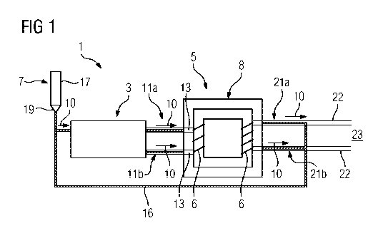
Figure 1 shows a basic diagram of a superconducting apparatus 1
according to a first exemplary embodiment of the invention. The
apparatus 1 comprises two coil devices 3 and 5, the components
to be cooled of said coil devices being cooled by a common
cooling apparatus 7. The cooling apparatus 7 comprises a cold
head 17 which is thermally coupled to a condenser 19. The
region of the condenser 19 is part of a closed cooling circuit
in which a coolant circulates in a pipe system in accordance
with the thermosiphon principle. The coolant is transported
from the condenser in liquefied form to the components to be
cooled of at least one of the two coil devices 3 and 5. Owing
to the absorption of heat from these components to be cooled,
the coolant can entirely or partially evaporate, so that, after
running through the two coil devices, either only gaseous
coolant or else a mixture of liquid and gaseous coolant is
CA 02969032 2017-05-26
, PCT/EP2015/076930
2014P23458W0US
- 15
:transported back to the condenser 19 by means of a return line
16. The gaseous coolant is again liquefied in the region of the
condenser 19, and the circuit is completed. The coolant can
comprise, for example, helium, neon or nitrogen.
Coolant flows through the two coil devices 3 and 5
sequentially. In the example shown, the two coil devices 3 and
are superconducting coil devices in which the windings of the
coils are formed from superconducting conductor material. The
first coil device 3 comprises all of the superconducting rotor
windings of an electrical machine. The further components of
the electrical machine are not illustrated in any detail here.
However, it additionally comprises a stator with normally
conducting or likewise superconducting stator windings, wherein
the stator radially surrounds the inner rotor. The
superconducting rotor windings are composed of a high-
temperature superconducting material.
The second coil device 5, which is likewise superconducting
here, is a transformer with superconducting transformer
windings 6 in this example. The transformer is arranged within
a thermally insulating cryostat 8 in order to improve cooling
of its superconducting windings 6. The windings 6 of the
transformer are also formed with a high-temperature
superconducting material here. However, the maximum operating
temperature of the transformer is somewhat higher than the
maximum operating temperature of the rotor windings since the
rotor windings have to have a relatively high critical magnetic
field and therefore also have to be cooled to a relatively low
operating temperature with the same choice of superconducting
material. Therefore, the components of the apparatus 1 are
expediently arranged such that the coolant which flows in from
the condenser 19 first flows through the first coil device 3
and there cools the rotor windings of the machine and only then
CA 02969032 2017-05-26
, PCT/EP2015/076930
2014P23458WOUS
- 16 -
,
,is transported to the region of the second coil device 5, that
is to say of the transformer, in the already somewhat heated
and possibly partially or completely evaporated state.
For the sake of completeness, it should be mentioned that the
rotor windings to be cooled of the first coil device 3 are also
arranged in a thermally insulating vessel, not shown here, so
that they are insulated from the warm outer environment.
Apparatuses for coupling coolant to and decoupling coolant from
the rotating components of the electrical machine, that is to
say for example into/from an interior of a rotor shaft, are
likewise not shown but are sufficiently well known from the
prior art.
It is essential to the present invention that the two coil
devices 3 and 5 are connected by at least one combined
connecting line lla. In the first exemplary embodiment shown,
two connecting lines ha and llb of this kind are arranged
between said coil devices, wherein each of these connecting
lines has an electrical conductor and a coolant pipe for
transporting coolant. Various possible exemplary embodiments
for the detailed construction of these connecting conductors
are described in greater detail in the text which follows.
However, they all share the common feature that the electrical
conductor of the connecting line is guided as part of a common
line together with the coolant pipe and is thermally
effectively coupled to said coolant pipe. This combined current
and cooling line is advantageously thermally effectively
insulated from the outer environment, for example by a
sheathing with vacuum insulation and/or wrapping by so-called
superinsulation. The electrical conductor of the connecting
line is likewise at a low operating temperature owing to the
thermal coupling to the coolant and can likewise have a high-
temperature superconducting material which can be connected
CA 02969032 21317-6
PCT/EP2015/076930
2014P23458W0US
- 17 -
,electrically in parallel to a normally conducting conductor.
Owing to this design, the electrical losses in the supply line
for the first coil device 3 are considerably reduced in
comparison to known designs with warm supply lines.
Furthermore, an additional thermal bridge is advantageously
avoided in the region of the first coil device 3 owing to a
direct connection to a warm outer circuit.
The second coil device 5, that is to say the superconducting
transformer, is provided with two additional outer connection
lines 21a and 21b. These connection lines 21a and 21b each also
have a region which is connected to the second coil device 5
and in which the coolant pipe and the electrical conductor of
the respective connection line are guided together in a
combined line. Following this common region, the coolant pipe
of the respective connection line is connected to a common
return line 16 for returning the coolant, and the electrical
conductors are electrically connected to the other, warm
components of an outer electrical circuit 23, not shown in
detail here, by means of separate current supplies 22.
In the first exemplary embodiment shown, the apparatus 1 has
two connecting lines ha and llb which run parallel to one
another and which each comprise an electrical conductor and a
coolant pipe, and in which the superordinate flow direction 10
of the coolant is the same. Here, coolant therefore flows
through the first coil device 3 and the second coil device 5 by
means of the two lines in succession in the same order.
However, other advantageous embodiments are also feasible, in
which the flow directions of the coolant can run opposite one
another in two connecting lines ha and llb which run next to
one another, so that a closed coolant circuit is already
produced by these connecting lines, that is to say without a
separate return line 16. In another possible alternative, two
CA 02969032 2017-05-26
PCT/EP2015/076930
2014P23458WOUS
- 18
pr more conductors, which are required for electrical contact-
making, can also be guided within a common connecting line ha
together with a coolant pipe. Therefore, it may be sufficient
to arrange only one single connecting line ha between the two
coil devices.
Figure 2 shows a basic illustration of an apparatus 1 according
to a second exemplary embodiment of the invention. A large
number of components are arranged analogously to the first
exemplary embodiment and are provided with the same reference
symbols. However, in contrast to the first exemplary
embodiment, no separate, outer return line 16 is connected to
the second coil device 5 here, but rather the two connecting
lines ha and lib each comprise two coolant pipes by means of
which coolant can be transported both from the rotor to the
transformer and also back to the rotor and from said rotor back
to the condenser 19. This is indicated in each case by the two
opposite flow directions 10 for each of the two connecting
lines. Various configurations for the connecting conductors ha
and 11b, which are explained in greater detail in the text
which follows, are also possible in an arrangement of this
kind. In this second exemplary embodiment, the current supplies
of the second coil device 5, that is to say the transformer
windings here, are connected to the outer electrical circuit 23
by means of separate current supplies 22. However, in
principle, it is also possible and may be advantageous to also
provide a coolant flow in the region of these current supplies
in order to reduce the line resistances. In this case, both
normally conducting and also superconducting line materials can
in general once again be used for the current supplies.
Figure 3 shows a schematic cross section through a connecting
line ha for one of the above-described apparatuses 1. The
connecting line ha of this third exemplary embodiment is
CA 02969032 2017-05-26
PCT/EP2015/076930
2014P23458WOUS
- 19
particularly suitable for use in an apparatus 1, as is
illustrated in figure 1, since there the coolant flows in each
of the connecting lines ha, lib only in one direction 10. The
connecting line ha shown in figure 3 comprises a coolant pipe
15, liquid and/or gaseous coolant 9 being transported in the
interior of said coolant pipe. The coolant pipe has, in the
region of its pipe casing, at least one electrically conductive
material which acts as an electrical conductor 13 of the
connecting line. By way of example, the pipe casing can be
formed from copper, and the cross section of the copper can be
sufficient to be able to ensure the current flow to be
transported from the current supply. The coolant pipe 15, which
therefore simultaneously serves as an electrical conductor 13,
can be electrically and thermally insulated from the outer
environment by further sheathing and/or wrapping.
As an alternative or in addition to the embodiment with a pipe
casing composed of copper, the pipe casing can also be coated
with an additional electrically conductive material of which
the conductivity and cross section are sufficient to be able to
transport the required current. The coating may also be a
superconducting coating of a conductive or else nonconductive
pipe. A suitable superconducting coating on pipe-like
substrates is, in particular, magnesium diboride which can be
deposited on rounded surfaces in a simple manner, for example,
by means of aerosol deposition.
In addition to the constituent parts shown in figure 3, the
connecting line ha can also have a further coolant pipe which
surrounds the inner pipe 15 and which can transport, for
example, coolant in the direction opposite the inner pipe. An
arrangement of this kind would also additionally make it easier
to cool a superconducting layer which is deposited on the
outside of the pipe 15. The resulting connecting line ha would
CA 02969032 2017-05-26
PCT/EP2015/076930
2014P23458W0US
- 20 -
,
,therefore also be suitable for use in the apparatus shown in
figure 2.
Figure 4 shows a schematic cross section of an alternative
connecting line ha according to a fourth exemplary embodiment
of the invention. The figure shows an inner coolant pipe 15a
which is radially concentrically surrounded by an outer coolant
pipe 15b. The electrical conductor 13, which can be designed as
a superconducting or as a normally conducting wire for example,
is guided within the inner coolant pipe 15a. More complex
conductive constructions comprising a plurality of materials
and layers, in which superconducting conductors and normally
conducting conductors can also be connected electrically in
parallel for example are also feasible. Coolant respectively
flows within the two shown coolant pipes 15a and 15b, wherein
the flow directions in the two pipes can advantageously be
opposite, in order to be able to cover both transportation
directions of the coolant by means of one connecting conductor.
The coolant in the inner coolant pipe 15a is particularly
advantageously the relatively cold coolant arriving from the
condenser, and therefore the electrical conductor 13 arranged
therein is particularly effectively cooled. The electrical
conductor can, as indicated in figure 4, be guided relatively
centrally within the inner pipe 15a by apparatuses not shown in
any detail here. However, as an alternative, said electrical
conductor can also be held in the region of one side of the
inner wall of the inner pipe 15a, since this can be easier to
reach. The electrical conductor 13 can be electrically
insulated from the coolant pipes 15a and 15b. Effective thermal
coupling of the conductor 13 to the through-flowing coolant is
important.
Figure 5 shows a schematic cross section of an alternative
connecting line lla according to a fifth exemplary embodiment
CA 02969032 21317-6
PCT/EP2015/076930
2014P23458W0US
- 21 -
,
of the invention. Said figure once again shows two interleaved
coolant pipes 15a and 15b through the interior of each of which
coolant 9 flows. In this example, a plurality of electrical
conductors in the form of individual conductor filaments are
mounted on the outer side of the inner pipe 15a, so that
coolant which is transported in the outer coolant pipe 15b
washes around these conductor filaments. Furthermore, said
conductor filaments are thermally coupled by means of the
material of the inner coolant pipe 15a to the coolant flowing
in said inner coolant pipe. In this case, selectively either
the coolant flowing on the outside or the coolant flowing on
the inside can form the colder of the two coolant flows. It is
important that the filaments of the electrical conductor 13 can
be cooled by the coolant 9 to such an extent that the
resistance in comparison to the ambient temperature is
considerably reduced. In this case, the electrical conductors
13 can once again comprise either normally conducting materials
and/or superconducting materials.
Figure 6 shows a schematic cross section of an alternative
connecting line ha according to a sixth exemplary embodiment
of the invention. Said figure once again shows two interleaved
coolant pipes 15a and 15b through the interior of each of which
coolant 9 flows. In this example, only one electrical conductor
13 is mounted on the outer side of the inner pipe 15a, so that
an asymmetrical and non-concentric design is realized. The
rectangular cross section of the electrical conductor 13 is
only exemplary in this case. Cross-sectional shapes different
to those shown can also be used both in the case of the coolant
pipes 15a, 15b and also in the case of the conductor 13. In
addition, the size relationships between the pipes 15a, 15b and
the conductors 13 are generally not true to scale, and the
drawings are intended to be understood only as schematic
diagrams.
CA 02969032 2017-05-26
PCT/EP2015/076930
2014P23458W0US
- 22
Figure 7 schematically shows a vehicle 25 according to the
invention which is in the form of a rail vehicle in this
example. Said vehicle has one of the above-described
apparatuses 1, wherein this apparatus comprises a machine 27
with superconducting rotor windings and a superconducting
transformer 29. The two components are cooled by the common
cooling apparatus 7, as has been explained in figures 1 and 2.
Although the invention has been illustrated and described in
more detail by the preferred exemplary embodiments, the
invention is not restricted by the disclosed examples and other
variations can be derived therefrom by a person skilled in the
art without departing from the scope of protection of the
invention.