Note : Les descriptions sont présentées dans la langue officielle dans laquelle elles ont été soumises.
CA 02969250 2017-05-29
WO 2016/108141 PCT/1B2015/059847
TUBULAR CONNECTION WITH SELF-LOCKING THREAD FORM USED IN THE OIL
INDUS TRY
CROSS-REFERENCE TO RELATED APPLICATIONS
[001] This application is related to U.S. Application No. 10/558,410, issued
as U.S. Patent
7,661,728, on February 16, 2010, the entire content of which is incorporated
in the present
document by reference, and to U.S. Application No. 13/139,522, filed on August
5, 2011, the
entire content of which is incorporated in the present document by reference.
BACKGROUND
[002] The present disclosure relates to a threaded tubular connection
comprising a male
tubular element comprising a male threading and female tubular element
comprising a female
threading which cooperates by makeup with said male threading.
[003] The axial width of the threads of said threading and valleys between
said threads vary
progressively along the axis of the connection over at least a portion of the
axial length of the
threadings, such that the threads of each threading are housed with an axial
clearance in the
valleys of the other threading at the start of makeup, said clearance
progressively decreasing
until it becomes zero during makeup.
[004] Threaded connections of this type generally have threads with a dovetail
profile, the
production of which is time consuming and costly. In addition, as the main
advantage of
such threaded connections is to provide superior torsional resistance, they
are likely to be run
into long laterals or used for drilling-with-casing or casing-while-drilling
applications where
higher level of torques are required. However, the increased level of stress
due to torque may
lead to a reduced fatigue performance which is an issue since those
applications also require
to maintain the sealability performance after several hours of rotation.
1
CA 02969250 2017-05-29
WO 2016/108141 PCT/1B2015/059847
SUMMARY
[005] A threaded connection with a first and a second tubular component, each
being
provided with a respective male and female end. The male end comprises on its
external
peripheral surface at least one threaded zone, and finishes in a terminal
surface which is
oriented radially with respect to the axis of the connection. The female end
comprises on its
internal peripheral surface at least one threaded zone, and finishes in a
terminal surface which
is oriented radially with respect to the axis of the connection.
[006] A width of the teeth of the male threaded zone, CWT, increases from a
value
CWTpmin corresponding to the width of the tooth which is closest to the
terminal surface of
the male end to a value CWTpmax corresponding to the width of the tooth which
is furthest
from said terminal surface. The width of the valleys of the male threaded
zone, CWRp,
increases from a value CWRpmin corresponding to the width of the valley which
is furthest to
the terminal surface of the male end to a value CWRpmax corresponding to the
width of the
valley which is closest from said terminal surface.
[007] A width of the teeth of the female threaded zone, CWTb, decreases from a
value
CWTbmax corresponding to the width of the tooth which is furthest from the
terminal surface
of the female end to a value CWTbmin corresponding to the width of the tooth
which is
closest to said terminal surface. The width of the valleys CWRb of the female
threaded zone
decreases from a value CWRbmax corresponding to the width of the valley which
is closest
from the terminal surface of the female end to a value CWRbmin corresponding
to the width
of the valley which is furthest to the terminal surface of the female end,
such that at least one
portion of the threaded zones cooperate in accordance with self-locking make-
up.
[008] The maximum width (CWTpmax, CWTbmax) and the minimum width (CWTpmin,
CWTbmin) of the teeth of the male and the female threads are configured such
that:
2
CA 02969250 2017-05-29
WO 2016/108141 PCT/1B2015/059847
CWT min
_____________________________________ >0.2
C WTb max
and
C WTb min CWTp min
CWTp max ¨ CWTb max
[009] The maximum width CWRpmax and the minimum width CWRpmin of the valleys
of
the male threads are configured such that CWRpmax < 3 CWRpmin.
[0010] The maximum width CWRbmax and the minimum width CWRbmin of the valleys
of
the female threads are configured such that CWRbmax < 3 CWRbmin.
BRIEF DESCRIPTION OF THE DRAWINGS
[0011] The characteristics and advantages of an exemplary embodiment are set
out in more
detail in the following description, made with reference to the accompanying
drawings.
[0012] Figure 1 depicts a diagrammatic view of a conventional connection
comprising a self-
locking thread form;
[0013] Figures 2 depicts a diagrammatic view of a conventional connection
comprising a
self-locking thread form;
[0014] Figure 3 depicts a detailed view of a conventional male end of a
tubular component of
a connection comprising a self-locking thread form;
[0015] Figure 4 depicts a detailed view of a conventional female end of a
tubular component
of a connection comprising a self-locking thread form;
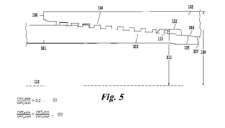
[0016] Figure 5 depicts a schematic cross-sectional view of an exemplary
embodiment;
[0017] Figure 6 depicts a schematic representation of a run-out groove portion
in an
exemplary embodiment;
[0018] Figure 7 depicts a detailed view of a male end of a tubular component
of a connection
3
CA 02969250 2017-05-29
WO 2016/108141 PCT/1B2015/059847
in an exemplary embodiment;
[0019] Figure 8 depicts a detailed view of a female end of a tubular component
of a
connection in an exemplary embodiment;
[0020] Figure 9 depicts a detailed view of two, male and female, threaded
zones of a
connection cooperating in self-locking interference in an exemplary
embodiment;
[0021] Figures 10 depicts a detailed view of the sealing zones according to an
exemplary
embodiment;
[0022] Figure 11 depicts a schematic representation of a taper line
configuration for an
exemplary embodiment;
[0023] Figures 12A-C depict a schematic representation of exemplary
embodiments of a run-
out;
[0024] Figure 13 depicts a schematic representation of an insert and a run-out
groove in an
exemplary embodiment;
[0025] Figure 14 depicts a schematic cross-sectional view of a second variant
of an
exemplary embodiment; and
[0026] Figures 15A-B and 16A-B depict levels of stress concentration in the
exemplary
embodiments of Figures 12A and 12C.
DETAILED DESCRIPTION
[0027] It is an object and feature of an exemplary embodiment described herein
to provide a
threaded tubular connection with a male tubular component and female tubular
component
and a thread geometry that meets the material properties requirements and
provides a sealed
contact. The threaded tubular connection can be made of steel. The mechanical
properties of
steel, i.e., yield strength, tensile strength, ductility, and the like make
steel a preferred
4
CA 02969250 2017-05-29
WO 2016/108141 PCT/1B2015/059847
material for the threaded tubular connection. The term sealed contact used in
the present
disclosure means contact between two surfaces pressed hard against each other
to produce a
metal-to-metal seal, in particular a gas-tight seal. An exemplary embodiment
increases the
stiffness of the connection and improves the fatigue behaviour of the
connection.
[0028] These and other objects, advantages, and features of the exemplary
threaded tubular
connection described herein will be apparent to one skilled in the art from a
consideration of
this specification, including the attached drawings.
[0029] Elements of a conventional tubular connection are shown in Figures 1-4.
Figure 1
illustrates a conventional threaded tubular connection that includes a tubular
element with a
male end 1 and a tubular element with a female end 2. Each end includes
respective tapered
threaded zones 3a, 4a which cooperate together for mutual connection by make-
up of the two
elements. The threaded zones 3a, 4a are of a "self-locking" type, which may
have a
progressive variation of the axial width of the threads and/or the valleys
between the threads,
such that a progressive axial interference fit is achieved during make-up and
into a final
locking position.
[0030] Figure 2 illustrates a distance VPEST (Virtual Positioning End of Self-
locking
Thread) that is defined from a terminal surface 7, wherein VPEST is the point
from which
constant width threads begin. Figure 2 further illustrates a distance PDAP
(Pitch Diameter
Axial Position) wherein the width of the male tooth and a female tooth are
equal. The concept
of PDAP is further illustrated in Figures 3 and 4.
[0031] As shown in Figures 3 and 4, the threaded zones 3a and 4a of a
conventional tubular
connection have a plane of symmetry 100 that is located at the distance PDAP
from the
terminal surface 7 of the male end. In this plane of symmetry 100, the width
of the male
tooth, CWTpref, and the width of the female tooth, CWTbref, adjacent to the
plane of
symmetry 100 are equal.
CA 02969250 2017-05-29
WO 2016/108141 PCT/1B2015/059847
[0032] As shown in Figures 3 and 4 with a longitudinal sectional view of the
male end 1 and
a longitudinal sectional view of the female end 2 of the conventional tubular
connection,
respectively, the width CWTpmin of the tooth (or thread) located closest to
the terminal
surface 7 of the male end 1 is the smallest value of the whole male threaded
zone 3a and also
corresponds to the width of the valley CWRpmin located furthest from said
terminal surface
7.
[0033] Similarly, as shown in Figures 3 and 4, in the conventional tubular
connection, the
width CWTbmin of the tooth (or thread) located closest to the terminal surface
8 of the female
end 2 is the smallest value of the whole female threaded zone 4a and also
corresponds to the
width of the valley CWRbmin located furthest from said terminal surface 8. In
order to obtain
a radial interference fit of the threaded zones, the width CWTpmin of the
narrowest tooth of
the male threaded zone 3a is equal to the width CWRbmin of the narrowest
valley of the
female threaded zone 4a.
[0034] In the conventional tubular connection as shown in Figures 3 and 4, the
narrowest
teeth of the male threaded zone 3a and female threaded zone 4a are
respectively clamped
between the corresponding teeth which are the widest. The narrow width of the
teeth close to
the terminal surface of the male and female ends as well as the large width of
the teeth which
clamp them may separately or in combination produce a risk of deterioration by
shear of
these narrow teeth.
[0035] A risk of shear is higher for the tooth with the minimum width CWTpmin
located on
the male end 1 than for the tooth with the minimum width CWTbmin located on
the female
end 2 since the male threaded zone 3a is imperfect close to the male teeth
which clamp the
minimum width tooth CWTbmin. Near the tooth with a minimum width CWTbmin, the
corresponding male teeth are of reduced height to allow a transition to the
non-threaded
portions and thus run a much lesser risk of causing the corresponding female
teeth to fail.
6
CA 02969250 2017-05-29
WO 2016/108141 PCT/1B2015/059847
[0036] For a connection resulting from collar between a long tubular component
carrying the
male end 1 and a short tubular component (termed a collar) carrying the female
end 2, for the
male end 1 the teeth are more imperfect close to the transition with the non-
threaded portions.
A risk that the male teeth will clamp the tooth with a minimum width CWTbmin
on the
female end is small.
[0037] Figure 5 illustrates a non-limiting embodiment of a tubular connection
system in
accordance with the present disclosure. The tubular connection system includes
a male
tubular element 101, and a female tubular element 102, including a threaded
male element
103, and a threaded female element 104, respectively. Alternatively, the
present disclosure
can also be applied to a three piece tubular connection with a collar.
[0038] In a non-limiting exemplary embodiment shown in Figure 5, the threaded
male
element 103 can include a male helical screw thread with a male crest, a male
root, a male
free end 107, a male stabbing flank, and a male loading flank. The male free
end 107 can be a
flat surface perpendicular to an axis of the threaded connection, as depicted
in the non-
limiting example of Figure 5. In an exemplary embodiment, the threaded female
element 104
can cooperate by makeup with the threaded male element 103. The threaded
female element
104 can include a female helical screw thread with a female crest, a female
root, a female free
end 108, a female stabbing flank, and a female loading flank. The female free
end 108 can be
a flat surface perpendicular to the axis of the threaded connection, as
depicted in the non-
limiting example of Figure 5. These elements are discussed in further detail
later in the
disclosure, for example, see the description accompanying Figure 9.
[0039] As shown in the exemplary embodiment of Figure 5, the female tubular
element 102,
also known as the box element, includes a run-out groove 112, located between
the threaded
female element 104, and the main portion of the female tubular element 102.
The run-out
groove 112 can have an inner diameter which is greater than the outer diameter
of the closest
7
CA 02969250 2017-05-29
WO 2016/108141 PCT/1B2015/059847
engaged thread. In other words, an inner diameter of the run-out groove is
greater than an
outer diameter of a last engaged tooth diameter. In an exemplary embodiment, a
critical
cross-section of the tubular connection system is a cross-section of the run-
out groove. The
critical cross-section is a cross-sectional area which undergoes full tension
transferred across
all threads and which is located, in this embodiment, at the terminal end 107
of the tubular
male element 101.
[0040] Figure 6 illustrates a non-limiting embodiment, in which the threaded
male element
103 includes a male tooth 133 present in the box run-out groove 112.
Alternatively, a female
tooth (not shown), instead of a male tooth 133, can be present in the box run-
out groove 112.
In either embodiment, there is a radial gap between the run-out groove 112 and
the tooth.
Figures 5 and 6 illustrate a non-limiting example of the radial gap between
the run-out groove
112 and the male tooth 133. In alternative embodiments, additional teeth can
be added in the
run-out groove 112.
[0041] Figure 7 illustrates an exemplary embodiment where the threads of the
threaded
female element 104 and threaded male element 103 can interlock as non-fully-
locking
threads. Non-fully locking threads can have an axial width of the threads of
the male
threading and the threads of the female threading and valleys between the
threads which vary
progressively along an axis of the connection 110 over at least a portion of
an axial length of
the threaded male element 103 and the threaded female element 104.
[0042] The threaded male element 103 can have a threaded portion with male
threads
separated by grooves, with width of the grooves CWRp increase from a value
CWRpmin
corresponding to a width of the groove which is furthest from a terminal
surface 107 of the
threaded male element 103, to a value CWRpmax corresponding to a width of the
groove
which is closest to the terminal surface 107 of the threaded male element 103.
[0043] The threaded female element 104, can have a threaded portion with
female threads or
8
CA 02969250 2017-05-29
WO 2016/108141 PCT/1B2015/059847
grooves, with a width of a groove CWRb which increases from a value CWRbmin
corresponding to a width of the groove which is furthest from a terminal
surface 108 of the
threaded female element 104, to a value CWRbmax corresponding to a width of
the groove
which is closest to the terminal surface 108 of the threaded female element
104.
[0044] In alternative embodiments, another type of thread may be used instead
of non-fully-
locking threads.
[0045] In an exemplary embodiment, the male end 107, also known as the pin
end, includes a
non-locking run-out, such that the makeup of the threaded male element 103 and
threaded
female element 104 are not limited by any axial abutment surface. In other
words, the male
free end 107 does not abut the female tubular element and the female free end
108 does not
abut the male tubular element. In an alternative embodiment, the additional
tooth 133 and the
run-out groove 112 are present but the makeup of the threaded male element 103
and
threaded female element 104 are limited by at least one axial abutment
surface. In other
words, at make-up between the threaded male element 103 and the threaded
female element
104 at least one thread of the male threaded end is located in the run-out
groove 112, and this
at least one thread is not in contact with the threaded female element.
[0046] In the exemplary embodiments shown in Figures 5-16, the geometry of
both the male
tubular element and the female tubular element, and their respective threaded
portions, may
be modified.
As shown in the exemplary embodiment of Figure 7, the threaded male element
103
cooperates with the threaded female element 104 with a standard length and
pitch, shown
respectively in Figure 8. In this exemplary embodiment, the ratio between the
width,
CWTpmin, of the tooth of the male end closest to the terminal surface 107 of
the male end
101 and the width, CWTbmax, of the tooth of the female end furthest from the
terminal
surface 108 of the female end 102 is selected to be 0.2 or more. The following
equation is
9
CA 02969250 2017-05-29
WO 2016/108141 PCT/1B2015/059847
obtained:
CWTP __ min > 0.2 [Equation #1]
CWTbmax ¨
[0047] In an exemplary embodiment, as the ratio of CWTpmin over CWTbmax
approaches 1,
a resistance of the connection to alternating tensile/compressive stresses is
improved.
[0048] In an exemplary embodiment, a portion of the threaded male element 103
where the
teeth are narrowest is reduced, resulting in the terminal surface 107 of the
male end 101 being
closer to the axis of symmetry 100 than when the portion of the threaded male
element 103
where the teeth are narrowest is not reduced. Thus, the width of the tooth
closest to the
terminal surface 107 is increased by attributing to it a value approaching
CWTpref which
corresponds to the width of the tooth adjacent to the axis of symmetry 100
prior to reducing
the portion of the threaded male element 103 where the teeth are narrowest.
For this reason,
the distance PDAP is reduced, which corresponds to the distance between the
axis of
symmetry 100 and the terminal surface 107.
[0049] In an exemplary embodiment, in order to maintain the total length of
the threaded
elements and maintain clamping torque, the threaded element of the end
opposite of the
terminal surface 107 is extended. For this reason, the ratio between the width
CWTbmin of
the tooth of the female end 102 closest to the terminal surface 108 of the
female end 102 and
the width CWTpmax of the tooth of the male end 101 furthest from the terminal
surface 107
of the male end 101 is reduced, relative to a conventional tubular connection.
This is
expressed by the following:
CWTbmin CWTpmin
[Equation #2]
CWTpmax CWTbmax
[0050] In an exemplary embodiment, the disproportion between the width CWTbmin
of the
tooth of the female end 102 closest to the terminal surface 108 of the female
end 102 and the
width CWTpmax of the tooth of the male end 101 furthest from the terminal
surface 107 of
CA 02969250 2017-05-29
WO 2016/108141 PCT/1B2015/059847
the male end 101 can be accentuated. In an exemplary embodiment, the teeth of
the male end
101 in this region can include a chamfer which attenuates the risk of shear
for the teeth of the
corresponding female end 102.
[0051] In an exemplary embodiment which maintains a standard total length of a
connection,
opposite the terminal surface 107 of the male end 101, the width of the
valleys is significantly
lower than the value CWRpmin corresponding to the minimum width of the valleys
in a
standard connection. To conserve a given length of the threaded zone and
conserve the value
of the pitch between the load flanks and between the stabbing flanks, and to
avoid a width
CWRpmin so small that the cutting tools used break during passage thereof, the
male
threaded element 103 can be modified. In an exemplary embodiment, the male
threaded
element 103 is modified when the width of the valleys of the threaded male
element 103
reaches a threshold value CWRpthreshold. In an exemplary embodiment, the
threaded male
element 103 can be modified to have the value, CWRpthreshold, of 0.7 or more
times the
tooth height.
[0052] In an exemplary embodiment, when the width of the valleys of the
threaded male
element 103 reaches a threshold value CWRpthreshold, the threaded male element
103 adopts
a profile in which one or more of teeth furthest from the terminal surface 107
are vanishing.
[0053] In an exemplary embodiment, to avoid a large thread portion in which
the teeth of the
threaded male element 3 no longer fit with radial interference, the distances
VPEST and
PDAP must be greater than a minimum value. In other words, to maintain a
length of self-
locking thread form required to guarantee a given make-up torque value, the
ratio
CWTpmin/CWTbmax must not be increased by too much, as otherwise it would be
necessary
to extend the portion of the threaded male element 103 in which the width of
the valleys
CWRp is subjected to the value CWRpthreshold.
[0054] In an exemplary embodiment, the ratio CWTpmin/CWTbmax is in a range
between
11
CA 02969250 2017-05-29
WO 2016/108141 PCT/1B2015/059847
0.3 to 0.7.
[0055] In an exemplary embodiment, for a threaded zone with a total length of
117 mm, it is
advantageous to place PDAP at a distance of 50 mm from the terminal surface
107 with
values for CWTpmin and CWTbmax of 2.7 mm and 5.3 mm, i.e. a ratio of 0.51. The
distance
at which the profile of the threaded male element 103 becomes constant is at a
distance
VPEST of 98 mm. The interference torque is maintained at 26000 ft lbs (35000 N
m) for a 5
1/2" 23.00 lbs/ft T95 collar, this is done without yielding the thread.
[0056] As shown in the exemplary embodiment of Figure 9, male threads 132 and
female
threads 142 (or teeth) can have a dovetail profile such that they are solidly
fitted into each
other after make-up. This avoids the risk of jump-out, which corresponds to
the male threads
132 and female threads 142 coming apart when the connection is subjected to
large bending
or tensile stresses. More precisely, the geometry of the dovetail threads
increases the radial
rigidity of their collar compared with threads which are usually termed
"trapezoidal" threads
wherein the axial width reduces from the base to the crest of the threads.
[0057] The term "self-locking threaded zones" means threaded zones comprising
the
characteristics detailed below. As shown in the exemplary embodiment of Figure
9, the male
threads (or teeth) 132, like the female threads (or teeth) 142, have a
constant pitch although
their width decreases in the direction of their respective terminal surface
107, 108 such that
during make-up, the male threads 132 and female threads 142 (or teeth) finish
by locking
into each other in a predetermined position. More precisely, the pitch LFPb
between the load
flanks 140 of the threaded female element 104 is constant, like the pitch SFPb
between the
stabbing flanks 141 of the threaded female element 104, with the feature that
the pitch
between the load flanks 140 is greater than the pitch between the stabbing
flanks 141.
Similarly, the pitch SFPp between the male stabbing flanks 131 is constant,
like the pitch
LFPp between the male load flanks 130. Further, the respective pitches SFPp
and SFPb
12
CA 02969250 2017-05-29
WO 2016/108141 PCT/1B2015/059847
between the male stabbing flanks 131 and female stabbing flanks 141 are equal
and smaller
than the respective pitches LFPp and LFPb between the male load flanks 130 and
female load
flanks 140, which are themselves equal.
[0058] As shown in the exemplary embodiment of Figure 9, the threaded male
element 103
and threaded female element 104 are oriented in a taper generatrix 120 to
facilitate the
progress of make-up. The taper generatrix 102 is defined as passing through
the center of the
load flanks. In an non-limiting exemplary embodiment, the taper generatrix 120
forms an
angle with the axis 110 which is in the range is between 1 degree to 5
degrees.
[0059] As shown in the exemplary embodiment of Figure 9, contact is
principally between
the male load flanks 130 and female load flanks 140, and between the male
stabbing flanks
131 and female stabbing flanks 141. In contrast, a clearance h may be produced
between the
male thread crests and the female thread roots, and similarly a clearance may
be provided
between the male thread roots and the female thread crests in order to
facilitate the progress
of make-up and prevent any risk of galling.
[0060] As shown in the exemplary embodiment of Figure 9, the crests of the
teeth and the
roots of the valleys of the threaded male element 103 and threaded female
element 104 can be
parallel to the axis 110 of the threaded connection. In an exemplary
embodiment, this
configuration can facilitate machining.
[0061] In an exemplary embodiment, a fluid seal is provided by two sealing
zones 105, 106
located near the terminal surface 107 of the male element 101, prevents leaks
from the
interior of the tubular connection to the external medium, and prevents leaks
from the
external medium into the tubular connection.
[0062] In an exemplary embodiment, as shown in Figure 10, sealing zone 105 of
the male
end 101 may have a domed surface 129 which is facing radially outwardly with a
diameter
which decreases towards the terminal surface 107. In an exemplary embodiment,
the radius
13
CA 02969250 2017-05-29
WO 2016/108141 PCT/1B2015/059847
of this domed surface 129 is preferably smaller than 150mm to avoid issues
associated with
cone-on-cone contact. In another exemplary embodiment, the radius of the domed
surface
129 is greater than 30mm to provide a sufficient contact area. In an exemplary
embodiment,
the radius of this domed surface 129 is preferably in the range 30 to 100 mm.
[0063] In an exemplary embodiment, as shown in Figure 10, opposite the domed
surface, the
sealing zone 106 of the female end 102 has a tapered surface 128 which faces
radially
inwardly with a diameter which decreases in the direction of the terminal
surface 107 of the
male element 101. The tangent of the peak half angle of the tapered surface
128 is in the
range 0.025 to 0.075, i.e. a taper in the range 5% to 15%. In an exemplary
embodiment, the
taper is at least 5% to reduce the risk of galling on make-up. In an exemplary
embodiment,
the taper is at most 15% to avoid issues associated with close tolerances for
machining.
[0064] The inventors have discovered that a contact zone between a tapered
surface and a
domed surface can produce a large effective axial contact width and a
substantially parabolic
distribution of contact pressures along the effective contact zone, in
contrast to contact zones
between two tapered surfaces which have narrow effective contact zones at the
ends of the
contact zone.
[0065] In an exemplary embodiment, with the domed surface and the tapered
surface, a
geometry for the contact zone can provide an effective contact width despite
variations in the
axial positioning of the coupled elements due to machining tolerances, the
effective contact
zone pivoting along the domed part of the domed surface, conserving a
parabolic profile for
the local contact pressure.
[0066] As shown in the exemplary embodiment of Figure 11, the pin seal is
configured
below the taper line 120 defined by the pin root thread, with a gap e. In this
embodiment, the
seal radial location is configured to be below the thread taper line. This
taper line
configuration allows straight-running, i.e. initial positioning of inserts
without plunging into
14
CA 02969250 2017-05-29
WO 2016/108141 PCT/1B2015/059847
the thread, for multiple teeth inserts. In a preferred embodiment the taper
line has a slope
between 5% and 25%, and the gap e is between 0.25 mm and 1 mm. In an
alternative
embodiment, the seal radial location is configured above the thread taper
line, and to use an
insert with multiple teeth, the length of the pin end is increased with
respect to the length of
the pin end when using an insert with a single tooth.
[0067] Figure 12A shows an exemplary embodiment with a standard run-out.
Figure 12B
shows an exemplary embodiment with a wider run-out, and Figure 12C shows an
exemplary
embodiment with a wider run-out and an additional tooth 133. Figure 6 shows a
detailed view
of the exemplary embodiment of Figure 12C.
[0068] In the exemplary embodiment of Figure 12A the run-out is not compatible
with a two
teeth insert, and machining time may be longer than machining time for the
exemplary
embodiments of Figure 12B or 12C.
[0069] With respect to the expected sealing performance calculated through
finite element
analysis, the exemplary embodiment of Figure 12C may provide less contact
pressure than
the exemplary embodiment of Figure 12A but can yield 10 to 30% more contact
pressure
than the exemplary embodiment of Figure 12B. The exemplary embodiment of
Figure 12C
reduces the stress bridge which is present between the critical cross section
and the seal area
in the exemplary embodiment of Figure 12A, as shown in Figures 15A-B and 16A-
B. In an
exemplary embodiment, the load flanks of the thread connect to the thread
crest and to the
adjacent thread root by roundings such that these roundings reduce the stress
concentration
factor at the foot of the load flanks and thereby improve the fatigue behavior
of the
connection. The exemplary embodiment of Figure 12C reduces stress
concentrations at the
root of the first engaged pin thread. In fatigue tests carried out, the
exemplary embodiment of
Figure 12C showed a survivability SAF of substantially 1.15 compared to DNV-B1
in air. In
an exemplary embodiment, an insert with multiple teeth is used to reduce
machining time by
CA 02969250 2017-05-29
WO 2016/108141 PCT/1B2015/059847
increasing the pass depth. An insert with two teeth can machine threads twice
as fast as an
insert with one tooth by removing twice as much as an insert with one tooth in
the same
amount of time. Machining is not negatively impacted by this configuration but
is actually
improved.
[0070] In an exemplary embodiment, a run-out groove 112 provides a space for
lubricating
fluid to escape, and a means to avoid pressure build-up. In an exemplary
embodiment, the
inner diameter of the run-out groove 112 is greater than the diameter of the
made-up teeth
adjacent to the run-out groove 112, such that with the presence of the run-out
groove 112 the
critical cross-section for the tubular assembly is no longer present at a
location where the
tubular elements contain threads. Instead, with the presence of the run-out
groove 112, the
critical cross-section for the tubular assembly is located at the run-out
groove 112, i.e. in a
non-threaded portion of the box component, effectively reducing the impact of
fatigue on the
component teeth. In an exemplary embodiment, the width of the run-out groove
is at least 1.5
to 2 times the loading flank pitch to allow the insert to be removed from the
threads after
machining. In an exemplary embodiment, a width of the run-out groove 112 is
configured to
be at least
LFPb + (1CW ¨ (LFPb ¨ SFPb)) + (LFH + LFPb-7) tan 15
[Equation #3]
where LFPb is the loading flank pitch, ICW is an insert crest width, SFPb is
the stabbing flank
pitch, LFH is the loading flank height, and TT is the taper line angle. The 15
angle is defined
relative to a plane 111 perpendicular to the axis of connection 110, as
illustrated in Fig. 13.
[0071] In an alternative embodiment, as shown in Figure 6, the additional
tooth present in the
run-out groove is not fully formed. In a preferred embodiment, the additional
tooth in the run-
out groove has a height of at least half the height of the fully formed tooth
closest to the end
of the tubular element.
[0072] The presence of this additional thread 133 yields a better stress
distribution along the
16
CA 02969250 2017-05-29
WO 2016/108141 PCT/1B2015/059847
pin, and increases pin lip stiffness under external pressure application, as
compared to an
embodiment without the additional thread, but similar in all other aspects. As
mentioned
above, the exemplary embodiment shown in Figure 12C and in Figures 16A-B
present an
improved stress distribution relative to the exemplary embodiment shown in
Figure 12A and
in Figure 15A-B. 15B and 16B illustrate the stress contours of each respective
embodiment
and Fig. 16B illustrates a reduced stress bridge in comparison to Fig. 15B.
[0073] In an exemplary embodiment, machining the pin end with an additional
tooth requires
additional machining time, but this is at least compensated by the reduction
in machining
time provided by the reduction in the number of middle passes carried out by
the selected
insert.
[0074] In an exemplary embodiment, the outside collar diameter 9, also
referred to as OD,
shown in the exemplary embodiment of Figure 1, is configured such that both
tension and
torsion criteria are met at a critical cross-section. In an exemplary
embodiment, the tubular
connection system is configured such that overall stress on the tubular
components does not
exceed 95% of yield strength, and such that the collar offers at least 102%
tensile
performance, to avoid any premature fatigue issues. The minimum collar outside
diameter 9
to ensure tensile efficiency is computed from the following:
OD _\11.02PS ¨4 + BGDax [Equation #4]
where OD is the outside diameter in millimeters, BGD. is the maximum box run-
out
groove diameter in millimeters, and PS is the pipe body section in millimeters
squared.
[0075] The minimum collar outer diameter to meet the yield strength criteria
is determined
by selecting OD according to the following:
o-vm = 0.95Y < + 3T2 [Equation #5]
where o-vmis the Von Mises equivalent stress, and Ys is the yield strength of
the material, o-ais
the principal axial stress under tension, and T is the shear stress generated
by torque on the
17
CA 02969250 2017-05-29
WO 2016/108141 PCT/1B2015/059847
outside of the collar.
[0076] The selected collar outside diameter 9 value is the largest value
obtained from the
above tensile efficiency and yield strength criteria, which ensures that the
collar diameter
meets both tension and torsion criteria.
[0077] In another exemplary embodiment, as shown in Figure 14, a tubular
connection
system can include two steps Si, S2. Accordingly, the first step Si includes a
threaded
connection portion between the male and female tubular elements, a run-out
groove, and an
additional tooth on the male tubular element which is located within the run-
out groove. The
second step S2 includes a second threaded connection portion between the male
and female
tubular elements, with a second run-out groove, and an additional tooth on the
male tubular
element, which is located within the second run-out groove. The second step S2
also includes
a metal-to-metal sealed contact portion. In this exemplary embodiment, the two
steps provide
a double metal-to-metal sealed contact. In an exemplary embodiment, a two-step
tubular
connection system can be used for integral joints or thick pipes for which a
secondary seal
may be useful.
Because many possible embodiments may be made of the present disclosure
without
departing from the scope thereof, it is to be understood that all matter
herein set forth or
shown in the accompanying drawings is to be interpreted as illustrative and
not in a limiting
sense.
18