Note : Les descriptions sont présentées dans la langue officielle dans laquelle elles ont été soumises.
WO 2015/085071 PCT/US2014/068572
FIN-BASED WATERCRAFT PROPULSION SYSTEM
CROSS-REFERENCE TO RELATED APPLICATIONS
[0001] This application claims the benefit of United States Patent Application
Serial Number
61/911,888, filed December 4, 2013, and United States Patent Application
Serial Number
61/936,419, filed February 6, 2014.
BACKGROUND
[0002] Design of propeller driven watercraft, including surface craft and
submarines, involves a
number of well known compromises involving propeller size, placement of the
engine, and hull
shape, to name but a few of the issues. In addition, the column of thrust
fluid propelled by a single
propeller rotates. Rotation of the thrust fluid does not produce thrust,
though is required in order
to move the thrust fluid backward (which does produce thrust). Thrust fluid
rotation can be
eliminated or at least balanced through the use of two counter-rotating
propellers, though this
results in twice the propeller surface area and (typically) twice as much
drive train complexity,
which reduces efficiency. In addition, efficient propeller-driven watercraft
achieve roughly 0.7 on a
graph of propulsive efficiency and thrust coefficient, and, even then, only in
a narrow range of
speeds. See, for example, "Hydrodynamic Flow Control in Marine Mammals", by
Frank E. Fish,
Laurens E. Howie, and Mark M. Murray, presented in the symposium, "Going with
the Flow:
Ecomorphological Variation across Aquatic Flow Regimes", presented at the
annual meeting of the
Society for Integrative and Comparative Biology, January 2-6, 2008, at San
Antonio, Texas, United
States, which shows an efficiency curve that is approximately an inverted
parabola. Travel faster
or slower than the speed where peak efficiency occurs, and the efficiency of
the propeller-driven
craft drops off rapidly.
[0003] In addition, propeller driven watercraft typically have a drive-shaft
which, when the engine
is inboard, penetrates the hull and creates the need for a drive-shaft seal
(outboard motors have a
severe bend in the drive-shaft, which reduces efficiency relative to inboard
motors). Drive-shaft
1
Date Recue/Date Received 2021-06-22
WO 2015/085071 PCT/US2014/068572
seals create friction, require maintenance, and introduce added mechanical
complexity (such as a
bilge pump).
[0004] Electric motors can be utilized which are flooded with a liquid and
which thereby reduce
the internal-external pressure differential on the drive-shaft seal. Such
motors are sometimes
found in submarines; however, such motors experience greater friction because
the rotor rotates in
a liquid, rather than in air, and maintenance is more complex.
[0005] In contrast to propellers, fins¨marine mammals and fish¨ have an
efficiency/thrust
coefficient of approximately 0.8 and the efficiency curve is very flat.
Traveling faster or slower than
the speed of peak efficiency results in only a modest change in efficiency.
While vortexes are
present in the thrust fluid propelled by a fin, unlike rotation of the column
of thrust fluid coming
off of a propeller, the vortexes behind a fin counter-rotate. The vortexes
form a "reverse von
Karman street" pattern, in which downstream vortices, as they spin and release
energy over time,
appear to pull upstream vortices further downstream, scavenging energy and
contributing to
overall thrust.
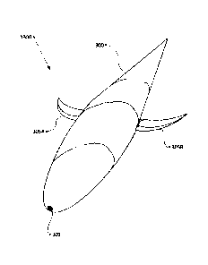
[0006] However, connecting a motor to a fin is a complex problem, particularly
in a marine
environment. Many fin-based propulsion systems have been designed and built,
some of which
produce a fish-like motion. Often, such systems have tens, hundreds, or even
thousands of
intricately machined parts with tight tolerances. Often, such systems have
multiple moving
bearings which are exposed to or which need to be sealed away from water by a
"wet" seal (which
attempts to seal the moving part or its bearings from water). Often, the
bearings in such craft
experience asymmetric loads, first on one side and then on the other. Some of
such systems rely
on exotic, expensive, and fragile materials, such as materials which contract
or expand in an
electric field.
[0007] The sheer number of parts, parts which move, seals, and asymmetrically
loaded bearings
reduce the efficiency of such systems, increase manufacturing costs, and
decrease reliability,
rendering most fin-based watecraft propulsion systems impractical for
commercial use.
[0008] Needed is an inexpensive, efficient, robust, fin-based propulsion
system.
2
Date Recue/Date Received 2021-06-22
CA 02969658 2017-06-02
WO 2015/085071 PCT/US2014/068572
[0009] Disclosed is an efficient fin-based propulsion system with only one
directly powered
component which, in some embodiments, is entirely sealed.
BRIEF DESCRIPTION OF THE DRAWINGS
[0010] Figure 1 illustrates a perspective view of an embodiment of a remotely
operated Fishboat
Vertical Torque Reaction Engine ("TRE") attached to a Barge, which Barge
carries a power source.
[0011] Figure 2 illustrates the Fishboat of Figure 1 in the same view, further
illustrating a Horizontal
Axis, Vertical Axis, Transverse Axis, and Waterline.
[0012] Figure 3A illustrates the perspective view of the Fishboat of Figure 1,
with a section cut
along the Horizontal Axis and a Symmetric Harness.
[0013] Figure 3B illustrates a Fishboat Vertical TRE embodiment with the same
view and section
cut of Figure 3A, but with an Asymmetric Bottom Harness.
[0014] Figure 3C illustrates a Fishboat Vertical TRE embodiment with the same
view and section
cut of Figure 3A, but with an Asymmetric Top Harness.
[0015] Figure 4A illustrates the Fishboat embodiment of Figure 3A, with
section cut, in a side
elevation parallel projection view.
[0016] Figure 4B illustrates the Fishboat embodiment of Figure 313, with
section cut, in a side
elevation parallel projection view.
[0017] Figure 4C illustrates the Fishboat embodiment of Figure 3C, with
section cut, in a side
elevation parallel projection view.
[0018] Figure 5A illustrates a close perspective view of an embodiment of a
Vertical TRE, generally
as found in the embodiments illustrated in Figures 1-4C, with a section cut
along the Horizontal
Axis.
[0019] Figure 5B illustrates a perspective view of a Top Bearing, an Inertial
Mass, a Stator Area, and
a Bottom Bearing of a Vertical TRE, generally as found in the embodiments
illustrated in Figures 1-
4C, with a section cut along the Horizontal Axis and with the components
partially disassembled.
[0020] Figure 5C illustrates a full TRE cycle.
3
CA 02969658 2017-06-02
WO 2015/085071 PCT/US2014/068572
[0021] Figure 6A illustrates a close parallel projection view of a portion of
a Vertical TRE, generally
as found in the embodiments illustrated in Figures 1-4C, with a section cut
along the Horizontal
Axis.
[0022] Figure 6B illustrates the view of the portion of the TRE of Figure 6A,
with lhertial Mass not
showing.
[0023] Figure 6C illustrates a detail of Figure 6A.
[0024] Figure 7 illustrates a front elevation parallel projection view of an
embodiment of a Vertical
TRE in a Fishboat embodiment, generally as found in the embodiments
illustrated in Figures 1-4C,
with a section cut along the Transverse Axis.
[0025] Figure 8A illustrates a front elevation parallel projection view of a
schematic embodiment of
a Vertical TRE in a Fishboat, further illustrating a Transverse TRE Position
Adjustor.
[0026] Figure 8B illustrates a side elevation parallel projection view of a
schematic embodiment of
a Vertical TRE in a Fishboat, further illustrating a Horizontal TRE Position
Adjustor.
[0027] Figure 9A illustrates a parallel projection view of certain electrical
and magnetic
components of an embodiment of a Vertical TRE with a section cut along the
Horizontal Axis.
[0028] Figure 9B illustrates a perspective view of certain electrical and
magnetic components of an
embodiment of a Vertical TRE in wireframe.
[0029] Figure 9C illustrates the view and components of Figure 98, in hidden-
line.
[0030] Figure 10 illustrates a top plan parallel projection view of an
embodiment of a Fishboat
Vertical TRE.
[0031] Figure 11A illustrates a parallel projection view of an embodiment of
Fluke-Flex adjustment
components in a first position.
[0032] Figure 116 illustrates the view and components of Figure 11A, with
Fluke-Flex adjustment
components in a second position.
[0033] Figure 12 illustrates a perspective view of an embodiment of a remotely
operated Fishboat
Vertical TRE attached to a Streamlined Battery Pack containing a power source.
[0034] Figure 13 illustrates a perspective view of an embodiment of a Fishboat
Horizontal TRE.
4
CA 02969658 2017-06-02
WO 2015/085071 PCT/US2014/068572
[0035] Figure 14 illustrates the Fishboat of Figure 13 in the same view,
further illustrating a
Horizontal Axis, Vertical Axis, and Transverse Axis.
[0036] Figure 15 illustrates the Fishboat of Figure 13, with a section cut
along the Horizontal Axis.
[0037] Figure 16 illustrates the Fishboat of Figure 13, further illustrating a
IRE within the Fishboat
with a section cut along the Transverse Axis.
[0038] Figure 17 illustrates the Fishboat of Figure 13 in a side elevation
parallel projection view.
[0039] Figure 18 illustrates an embodiment of a Hull interior of the Fishboat
of Figure 13 in the
side elevation parallel projection view of Figure 17.
[0040] Figure 19 illustrates an embodiment of a Stator Shell and Spindle of
the Fishboat of Figure
13 in the side elevation parallel projection view of Figure 17.
[0041] Figure 20 illustrates an embodiment of an Inertial Mass and Rotor of
the Fishboat of Figure
13 in the side elevation parallel projection view of Figure 17, with a section
cut along the
Horizontal Axis.
[0042] Figure 21 illustrates the Fishboat of Figure 13 in the side elevation
parallel projection view
of Figure 17, with a section cut along the Horizontal Axis.
[0043] Figure 22 illustrates the Fishboat of Figure 13 in front elevation
parallel projection view.
[0044] Figure 23 illustrates the Fishboat of Figure 13 in front elevation
parallel projection view,
with a section cut along the Transverse Axis.
[0045] Figure 24A illustrates a close perspective view of a Fin embodiment.
[0046] Figure 24B illustrates the close perspective view of the Fin embodiment
of Figure 24A, with
the Fin not shown to illustrate an embodiment of Fin-Flex Adjustment
components.
[0047] Figure 25A illustrates a close perspective view of a Fin embodiment.
[0048] Figure 25B illustrates the close perspective view of the Fin embodiment
of Figure 25A, with
the Fin not shown to illustrate an embodiment of Fin-Flex Adjustment
components.
[0049] Figure 26A illustrates the Fishboat of Figure 13 attached to a Barge
via a Hawser.
[0050] Figure 26B illustrates the Fishboat of Figure 13 attached to a Barge
via a Whisker Pole.
[0051] Figure 27A illustrates a detail perspective view of an embodiment of a
connection point for
WO 2015/085071 PCT/US2014/068572
a Harness.
[0052] Figure 27B illustrates the detail view of Figure 26A, further
comprising Harness
components.
[0053] Figure 28A illustrates an embodiment of a Direct Drive Craft.
[0054] Figure 28B illustrates the Direct Drive Craft of Figure 27A with a
section cut through the
Horizontal Axis.
[0055] Figure 29 illustrates a detail of the Direct Drive Craft of Figure 26A
with a section cut
through the Horizontal Axis.
[0056] Figure 30 illustrates an embodiment of a set of circuits which may be
used to control a TRE
and a Fish boat or a Direct Drive Craft.
[0057] Figure 31 is a graph of the efficiency over coefficient of thrust for
propellers and cetaceans
showing a comparison of relationships of propulsive efficiency and thrust
coefficient for four
species of small cetaceans and a typical marine propeller, wherein data for
whales were
obtained from Fish (1998a, b) and data for the propeller (EMB 2294) were from
Saunders
(1957).
DETAILED DESCRIPTION
[0058] It is intended that the terminology used in the description presented
below be interpreted
in its broadest reasonable manner, even though it is being used in conjunction
with a detailed
description of certain examples of the technology. Although certain terms may
be emphasized
below, any terminology intended to be interpreted in any restricted manner
will be overtly and
specifically defined as such in this Detailed Description section.
[0059] Unless the context clearly requires otherwise, throughout the
description and the claims,
the words "comprise," "comprising," and the like are to be construed in an
inclusive sense, as
opposed to an exclusive or exhaustive sense; that is to say, in the sense of
"including, but not
limited to:' As used herein, the term "connected," "coupled," or any variant
thereof means any
connection or coupling, either direct or indirect between two or more
elements; the coupling of
connection between the elements can be physical, logical, or a combination
thereof. Additionally,
the words, "herein," "above," "below," and words of similar import, when used
in this application,
shall refer to this application as a whole and not to particular portions of
this application. When
6
Date Recue/Date Received 2021-06-22
CA 02969658 2017-06-02
WO 2015/085071 PCT/US2014/068572
the context permits, words using the singular may also include the plural
while words using the
plural may also include the singular. The word "or," in reference to a list of
two or more items,
covers all of the following interpretations of the word: any of the items in
the list, all of the items in
the list, and any combination of one or more of the items in the list.
References are made herein
to routines and subroutines; generally, it should be understood that a routine
is a software
program executed by computer hardware and that a subroutine is a software
program executed
within another routine. However, routines discussed herein may be executed
within another
routine and subroutines may be executed independently (routines may be
subroutines and visa
versa).
[0060] As used herein, "releasable," "connect," "connected," "connectable,"
"disconnect,"
"disconnected," and "disconnectable" refers to two or more structures which
may be connected or
disconnected, generally without the use of tools (examples of tools including
screwdrivers, pliers,
wrenches, drills, saws, welding machines, torches, irons, and other heat
sources) and generally in a
repeatable manner. As used herein, "attach," "attached," or "attachable"
refers to two or more
structures or components which are attached through the use of tools or
chemical or physical
bonding. As used herein, "secure," "secured," or "securable" refers to two or
more structures or
components which are either connected or attached.
[0061] Described herein are Fishboat and Direct Drive watercraft. Illustrated
examples of Fishboat
embodiments include Fishboat Vertical TRE 100 and Fishboat Horizontal TRE
1300. Examples of
Direct Drive embodiment include Direct Drive Horizontal Engine 270.
[0062] As described further herein, Fishboats are watercraft in which a torque
reaction engine
("TRE") is within a Capsule, which Capsule may be sealed. The TRE causes the
Capsule to cyclically
counter-rotate, in one direction and then the other, about a central axis.
Cyclic counter-rotation of
the Capsule (also referred to herein as "oscillation") is communicated to a
Hull or other force
transmitting member (referred to herein as a "Hull") which is secured to and
generally surrounds
the Capsule, producing oscillating yaw when the TRE is oriented on Vertical
Axis 225, oscillating
pitch when the TRE is oriented on Transverse Axis 230, and oscillating roll
when the TRE is oriented
7
CA 02969658 2017-06-02
WO 2015/085071 PCT/US2014/068572
on Horizontal Axis 235.
[0063] Fin(s) are secured to the Hull. Cyclic counter-rotation (or
oscillation) of the Capsule-Hull-
Fin(s) through the surrounding thrust fluid generates thrust. In embodiments
in which the Hull is a
force transmitting member such as a beam, a fairing may be provided in
addition to the Hull to
streamline the flow of fluid around the Fishboat.
[0064] The TRE comprises a Rotor and a Stator. An Inertial Mass is secured to
the Rotor; the Rotor
and Inertial Mass are cyclically counter-rotated (or oscillated) by the
Stator, in one direction and
then the other, about an axis of rotation. Cyclic counter-rotation of the
Inertial Mass causes an
alternating torque reaction on the Stator. The Stator is secured to or forms
the interior of the
Capsule. The alternating torque reaction on the Stator causes the Capsule to
cyclically counter-
rotate. The Inertial Mass may be symmetric about a central axis shared with
the Motor, though in
alternative embodiments, the Inertial Mass may asymmetric about the Motor's
central axis.
[0065] The central axis of the Motor may be, for example, the Horizontal Axis
235, Vertical Axis
225, or Transverse Axis 230 (see Figure 2 or equivalent axis illustrated in
Figure 14). If the TRE is
oriented around a Vertical Axis 225¨as in example embodiment of Fishboat
Vertical TRE 100¨the
TRE causes oscillating yaw of the Fishboat about the Vertical Axis 225 and the
Fishboat swims like a
fish, with a vertically oriented rear Fin. If the TRE is oriented around a
Transverse Axis 230, the TRE
causes oscillating pitch of the Fishboat about the Transverse Axis 230 and the
Fishboat swims like a
marine mammal, with a horizontally oriented rear Fin¨as in an example
embodiment in Figure 7
of US Provisional Patent Application Serial Number 61/911,888. If the TRE is
oriented along a
Horizontal Axis 235, the TRE causes oscillating roll of the Fishboat about the
Horizontal Axis 235
and the Fishboat swims with a cyclically counter-rotating (or oscillating)
screw-type motion, as in
embodiments of Fishboat Horizontal TRE 1300.
[0066] The Motor may be an "outrunner" style electric motor, in which a
central Stator is
surrounded by a Rotor and the Inertial Mass is secured to the Rotor. The Motor
and Inertial Mass
may be provided by an internal combustion engine or the like, though this
paper uses an electric
motor as an example of the TRE, because electric motors are mechanically
simple, do not require
8
CA 02969658 2017-06-02
WO 2015/085071 PCT/US2014/068572
flow of an oxidizer or other chemicals into and exhaust of combustion or other
reaction products
out of the TRE and are flexible inasmuch as a wide range and rate of rotations
of the Inertial Mass
may be implemented. In embodiments in which the Motor is electric, a brushless
DC motor may be
used. A mechanically commutated brushed electric motor may be used, though a
brushless motor
offers reduced maintenance. A combustion-based TRE may utilize various rotary
motor
configurations, such as wherein a piston (including equivalent structures in a
rotary engine)
cyclically compresses and ignites gas and fuel in an enclosure, with release
of the exhaust gases
cyclically oscillating the Inertial Mass. As noted, the Inertial Mass may be
asymmetric, though
embodiments illustrated in this paper discuss a symmetric Inertial Mass.
[0067] The Inertial Mass may be provided by, for example, lead, iron, a
battery pack, or the like.
[0068] In the case of an electric Motor, electrical power may be obtained from
a Power Source.
The Power Source may be on a Barge or other vessel towed by the Fishboat or
the Power Source
may internal to the Fishboat. If towed on a Barge, the Power Source may be a
solar panel, a
battery pack, a fuel cell, or a generator (wind, fossil fuel, or the like). If
internal to the Fishboat, the
Power Source may be a battery pack or fuel for an internal combustion engine.
An embodiment is
illustrated in Figure 12 in which the Power Source is towed in a vessel such
as a Steamlined Battery
Pack 205.
[0069] Fin(s) may be secured to the Fishboat. If secured to the Fishboat at
the center of
displacement of the Fin (which is also generally the wide point, 1/3rd back
from the leading edge
of the Fin, for a typical wing cross-section), but with nothing to resist
rotation, Fin(s) will find the
path of least resistance through the thrust fluid. Flexible Beam(s) may be
included in the
securement between Fin(s) and Fishboat, causing the Fin(s) to deflect in the
thrust fluid less than
the path of least resistance, causing the Fin(s) to achieve an angle of attack
sufficient to generate
thrust. The bending modulus of the Flexible Beam may be adjustable, to change
the angle of
attack achieved by the Fin(s). Though generally the Flexible Beam passively
articulates due to
forces experienced by the Fin as the Fin(s) translate through the thrust fluid
(allowing the Fins to
find the angle of attack based on the modulus of flexibility), the Flexible
Beam may comprise
9
CA 02969658 2017-06-02
WO 2015/085071 PCT/US2014/068572
actuator(s) to bend the Flexible Beam or to change the normal angle between
the Flexible Beam
and the Hull, which may be done for purposes of achieving a desired angle of
attack or which may
be done to steer the Fishboat.
[0070] The Fishboat may also be steered by re-positioning the center of
gravity of the TRE relative
to the Fin and Hull. For example, in a Fishboat in which the TRE rotates about
the Vertical Axis 225
to produce thrust and in which the TRE has a center of gravity located below
the Horizontal Axis
235, the Capsule may be re-positioned along the Transverse Axis 230, which
causes the Fishboat to
= roll to an angle off of horizontal and results in a steering force. See,
for example, Figures 8A and
8B. The Fishboat may also be steered by producing more torque with the TRE on
one side of it's
cycle (such as by counter-oscillating the TRE further in one direction than
the other) or by relaxing
the Flexible Beam on one side, which may result in a difference in thrust
between the sides, which
produces a steering force.
[0071] The Fishboat comprises sensors to detect the relative and/or absolute
position of various
components and/or the strain experienced by components. For example, sensors
may be present
to sense a bend in the Flexible Beam, to detect the orientation of the craft
(in terms of roll, pitch,
and yaw), the position of the Inertial Shell and Rotor relative to the Stator,
the orientation of the
center of gravity of the TRE relative to the Hull, the orientation and angle
of attack of the Fin(s), the
status of the Stator and Rotor (such as magnetic fields, electrical current,
etc.), the status of the
Power Source, and the like.
[0072] The sensors may be part of electronic circuits, some of which may form
feedback circuits,
such as a circuit which controls power to the Stator and rotates the Inertial
Shell until the craft
yaws, rolls, or pitches (in the opposite direction of the rotation of the
Inertial Shell) to a selected
position relative to the normal direction of travel or until a bending angle
is achieved in the Flexible
Beam or until an angle of attack is obtained in the Fin(s), whereupon the
feedback circuit may
cause the rotation of the Inertial Shell to slow and reverse until the craft
yaws or rolls in the other
direction to an equivalent position, whereupon the rotation of the Inertial
Shell may be slowed and
reversed again, etc. When the Fishboat is at rest, the bending modulus of the
Flexible Beam may
CA 02969658 2017-06-02
WO 2015/085071 PCT/US2014/068572
be started at a flexible setting, with the bending modulus made more stiff as
speed increases.
[0073] The Direct Drive Craft is an embodiment with even fewer moving parts
and no Inertial
Mass, but which requires a flexible membrane, such as Membrane 285, a wet
seal, or water
tolerant bearings.
[0074] Both Fishboat and Direct Drive Craft are mechanically simple,
physically robust, and provide
greater efficiency than propeller driven craft.
[0075] Figure 1 illustrates a perspective view of an embodiment of a remotely
operated Fishboat
Vertical TRE 100 attached to a Barge 105, which Barge 105 carries a Power
Source 110. Identified
in this Figure are Nose 130, Tail 135, Fluke 215, Top Bearing 160, Central
Tube 185, Symmetrical
Harness 115, and Tether 120. Nose 130 and Tail 135 have approximately the same
displacement.
Displacement between Nose 130 and Tail 135 may be adjustable, to change the
normal pitch of the
craft. Overall displacement of the entire craft may be increased or decreased
to change the normal
depth of the craft in the water.
[0076] Figure 2 illustrates the Fishboat of Figure 1 in the same view, further
illustrating Horizontal
Axis 235, Vertical Axis 225, Transverse Axis 230, and Waterline 240. As
discussed herein, roll is
rotation about Horizontal Axis 235, yaw is rotation about Vertical Axis 225,
and pitch is rotation
about Transverse Axis 230.
[0077] Figure 3A illustrates the perspective view of the Fishboat of Figure 1,
with a section cut
along Horizontal Axis 235 and Symmetric Harness 115 and Catenary 120. Figures
1, 2, and 3A and
Fishboat Vertical TRE 100 may be compared, one page and figure to the other.
The securement
point between Catenary 120 and Symmetric Harness 115 may be moved up or down
along the
trailing arc of Symmetric Harness 115, such as to change the pitch of the
Fishboat.
[0078] Figure 3B illustrates a Fishboat Vertical TRE embodiment with the same
view and section
cut of Figure 3A, but with an Asymmetric Bottom Harness 140, generally forming
a catenary drape.
[0079] Figure 3C illustrates a Fishboat Vertical TRE embodiment with the same
view and section
cut of Figure 3A, but with an Asymmetric Top Harness 150 and Catenary 151. To
change the weight
of Asymmetric Bottom Harness 140 or Catenary 120 or Catenary 151, more or less
Harness may be
11
CA 02969658 2017-06-02
WO 2015/085071 PCT/US2014/068572
released from or drawn back onto Barge 105. Components may be incorporated
into the
attachment point between Symmetric Harness 115, Asymmetric Bottom Harness 140,
or
Asymmetric Top Harness 150, to change the normal angle between the Harness and
the craft, for
example, to cause the Fishboat to pitch or to allow more room between the
Fluke and the Harness.
[0080] Figure 4A illustrates the Fishboat embodiment of Figure 3A, with
section cut, in a side
elevation parallel projection view.
[0081] Figure 4B illustrates the Fishboat embodiment of Figure 3B, with
section cut, in a side
elevation parallel projection view.
[0082] Figure 4C illustrates the Fishboat embodiment of Figure 3C, with
section cut, in a side
elevation parallel projection view.
[0083] Figure 5A illustrates a close perspective view of an embodiment of
Vertical IRE 500,
generally as found in the embodiments illustrated in Figures 1-4C, with a
section cut along
Horizontal Axis 235. Illustrated are Nose 130 and Tail 135, which contact Top
Bearing 160 and
Bottom Bearing 165. Top Bearing 160 and Bottom Bearing 165 support Inertial
Mass 155 and allow
Inertial Mass 155 to rotate about Vertical Axis 225. The Bearings may be
located closer to Central
Tube 185. In this embodiment, Inertial Mass 155 is faced with Permanent
Magnets 156. Magnets
156 (which may be permanent) interact with Electromagnets 175 in Stator 170.
Also illustrated are
Rectifier 178, Space 179, Capacitor 180, Central Tube 185, and a Harness, in
this example,
Symmetrical Harness 115. Central Tube 185 and the Harness may be mediated by a
bearing, such
as a water tolerant set of ball bearings, though they may also be mediated by
a bearing interface
between the components, such as a brass-on-brass interface. In an example
illustrated in Figures
26A and 26B, a Hitching Post 345 may project through the Central Tube 185 and
secured with
Collar 250.
[0084] Electric power may be delivered through the Harness or through power
lines which exit the
Harness and, via Energy Transfer Circuit 415 (see Figure 30), enter Capacitor
180. Capacitor 180 is
labeled as a "capacitor'', but may be another power reservoir, such as a
capacitor, a battery, or the
like. Ultracapacitors can be cycled 500,000 to 1 million times, and require
little to no maintenance.
12
CA 02969658 2017-06-02
WO 2015/085071 PCT/US2014/068572
Power exits Capacitor 180 and enters Power Transfer Circuit 420, which may
incorporate or be
connected to Rectifier 178, which may deliver power, such as three-phase
power, to TRE or Motor
400. Rectifier 178 may utilize DC-DC boost to extract braking energy at lower
speeds. A circuit
diagram is provided in Figure 30. Part or all of Energy Transfer Circuit 415
may be located in Space
179 and/or in Cavity 168 or Cavity 169 between Bottom Bearing 165 or Top
Bearing 160 the
interior wall of Stator 170 frame and/or on the Barge. Power Transfer Circuit
420 may be present in
Rectifier 178 and/or in Cavity 168 or Cavity 169. Control Circuit 425 may
control Motor 400, Power
Transfer Circuit 420, Energy Transfer Circuit 415, and may obtain information
from and/or control
Sensors-Actuators 430.
[0085] Figure 5B illustrates a perspective view of Top Bearing 160, Inertial
Mass 155, Stator 170,
and Bottom Bearing 165, generally as found in the embodiments illustrated in
Figures 1-4C, with a
section cut along the Horizontal Axis and with the components partially
exploded (in Figure 5B,
Bottom Bearing 165 is in position relative to Stator 170). A conventional
"outrunner" electric
torque motor may be used, with Inertial Mass mounted to the rotor.
[0086] Figure 5C illustrates a full TRE cycle, starting from the top, with
acceleration of Inertial Mass
in a counter-clockwise direction, illustrated in Arc 181, which produces a
torque reaction in Stator
which drives Stator in a clockwise direction, illustrated in Arc 182, followed
by acceleration of
Inertial Mass in a clockwise direction, illustrated in Arc 183, which produces
a torque reaction in
Stator which drives Stator in a counter-clockwise direction, illustrated in
Arc 184.
[0087] Figure GA illustrates a close parallel projection view of a portion of
Vertical TRE 500,
generally similar to the TRE embodiments illustrated in Figures 1-4C, with a
section cut along
Horizontal Axis 235. Figure 6B illustrates the view of the portion of the
Vertical TRE 500 of Figure
6A, with Inertial Mass 155 not showing. Also labeled in this Figure are
Bearing Top 162 and Bearing
Bottom 163. Bearings 162 and 163 are illustrated as ball bearings, though
bearings of another
shape may be used, such as, for example, roller bearings. Figure 6C
illustrates a detail of Figure 6A.
Together, Figure 6A-6C illustrate components which do not move, relative to
the one component
which moves, Inertial Mass 155. Figure 6C also illustrates the air gap between
Inertial Mass 155-
13
CA 02969658 2017-06-02
WO 2015/085071 PCT/US2014/068572
Magnet 156 and Stator 170. Per the discussion above, Electromagnets 175 in
Stator 170 rotate
Magnets 156 in Inertial Mass 155 first one way, then the other, around
Vertical Axis 225, causing
an opposing torque reaction in Electromagnets 175 and Stator 170. Because
Electromagnets 175
and Stator 170 are anchored in or otherwise secured to Hull (in, for example,
Nose 130 and Tail
135), the opposing torque reaction in Electromagnets 175 and Stator 170 is
communicated to
Fin(s), such as, for example, Fluke 215.
[0088] Figure 7 illustrates a front elevation parallel projection view of an
embodiment of a
Fishboat Vertical TRE, generally as found in the embodiments illustrated in
Figures 1-4C, with a
section cut along the Transverse Axis and many of the elements identified by
number. Figure 7 also
illustrates Outer Shell 136 and Capsule 133
[0089] Figure 8A illustrates a front elevation parallel projection view of a
schematic embodiment of
a Vertical TRE in a Fishboat, further illustrating Transverse TRE Position
Adjustor 137. Figure 88
illustrates a side elevation parallel projection view of a schematic
embodiment of a Vertical TRE in a
Fishboat, further illustrating a Horizontal TRE Position Adjustor 139.
Transverse TRE Position
Adjustor 137 and Horizontal TRE Position Adjustor 139 may be used to adjust
the position of
Capsule 133, containing TRE. Adjustment of position may be performed to trim
the orientation of
the craft in the water and/or to provide a steering force. As illustrated,
Capsule 133 is located
approximately at the center of displacement and slightly below Horizontal Axis
235. Motor(s) (not
illustrated) may provide power to drive Transverse TRE Position Adjustor 137
and Horizontal TRE
Position Adjustor 139.
[0090] Figure 9A illustrates a parallel projection view of certain electrical
and magnetic
components of an embodiment of a Vertical TRE 900 with a section cut along the
Horizontal Axis.
Figure 9B illustrates a perspective view of certain electrical and magnetic
components of the
Vertical TRE of Figure 9A, in wireframe and without the section cut. Figure 9C
illustrates the view,
components, and reference numbers of Figure 9B, in hidden-line (which helps to
identify where the
number lines in Figure 9B point to). Labeled in Figures 9A-9C are Inertial
Mass 155, Bottom Bearing
165, Hall Effect Sensor(s) and Hall Effect Sensor wires 201, Electromagnets
175, Rectifier 178,
14
CA 02969658 2017-06-02
WO 2015/085071 PCT/US2014/068572
Capacitor 180, and Winding-Rectifier Connection Wires 195. Because the
Rectifier may be split into
two components (the Rectifier may be in just the top or just the bottom), the
Winding-Rectifier
Connection Wires 195 are illustrated extending both upward and downward. Hall
Effect Sensor(s)
may be hall effect sensors, optical position sensors, or other sensors which
detect the position of
Inertial Mass 155 and/or Magnet(s) 156 (or DD Rotor 280) relative to Stator
170 and
Electromagnets 175.
[0091] Various winding patterns may be followed for Electromagnets in Stator.
For example, Wye
configuration gives high torque at low speed, but not as high top speed, which
may be desirable in
this context.
[0092] Figure 10 illustrates a top plan parallel projection view of an
embodiment of a Fishboat
Vertical IRE 1000. An arrow arc indicates oscillation of the aft of Fishboat
Vertical IRE 1000 due to
torque reaction. A corresponding oscillation occurs at the bow of Fishboat
Vertical IRE 1000.
[0093] Figure 11A illustrates a parallel projection view of an embodiment of
Flexible Beam
adjustment components in a first position. Figure 11B illustrates the view and
components of
Figure 11A, with Fluke-Flex adjustment components in a second position. In the
embodiment
illustrated in these Figures, Fluke 215 is secured to Flexible Beam 217, which
may be, for example,
a rod made of carbon fiber or another flexible material. Flexible Beam may
extend into Tail 135,
inside of a tube with an inside diameter just slightly larger than the outside
diameter of Flexible
Beam 217, allowing Flexible Beam 217 to slide back and forth within the tube
within Tail 135. Fluke
Extender 245 may comprise components, such as a motor, a rack and pinion
system, a hydraulic
system, or the like, to slide Flexible Beam 217 back and forth within the tube
within Tail 135. When
Flexible Beam 217 is extended, as in Figure 11B, Fluke 215 will deflect
further when the Fishboat
yaws about Vertical Axis 225 than when Flexible Beam 216 is withdrawn inside
of the tube within
Tail 135. This is an example embodiment of components to change or adjust the
bending modulus
of the Flexible Beam, which will change the angle of attack achieved by Fluke
215 when the craft
yaws back and forth, driven by IRE.
[0094] Flexible Extender 245 may logically connect to Control Circuit 425 via
Deflection Sensor-
CA 02969658 2017-06-02
WO 2015/085071 PCT/US2014/068572
Actuator Connector 247, providing information to Control Circuit 425 regarding
the length of
extension of Flexible Beam 217, regarding the deflection of Flexible Beam 217,
regarding the
orientation of Flexible Beam 217 relative to the Hull, and the like.
[0095] Flexible Beam 217 may rotate on the horizontal plane about its
connection with Tail 135,
such as by operation of a motor which may pull Flexible Extender 245 back and
forth withing Tail
135, allowing Flexible Beam 217 and Fluke 215 to be used to provide a steering
force (for an
alternative embodiment, see, for example, Figures 104 and 10B in United States
Provisional Patent
Application Serial Number 61/911,888, in which a steering disk is located at
the connection point
between the Fluke and the Tail).
[0096] Figure 12 illustrates a perspective view of an embodiment of a remotely
operated Fishboat
Vertical TRE 1200 attached to a Streamlined Battery Pack 205 containing a
Power Source, such as a
battery. The position of the Streamlined Battery Pack 205 may be adjusted,
such as up and down
along the trailing arc of Symmetrical Harness 115, to change the pitch of the
Fishboat. Streamlined
Battery Pack 205 may also be used to steer the Fishboat 1200. Streamlined
Battery Pack 205 may
be used with a Harness which is not symmetrical.
[0097] Figure 13 illustrates a perspective view of an embodiment of a Fishboat
Horizontal TRE
1300. Identified are Spinner Hull 300, Starboard Fin 3054, Port Fin 305B, and
Sensor Hole 301.
Spiral lines are drawn on Spinner Hull 300 in these figures to provide a
visual reference.
[0098] Figure 14 illustrates the Fishboat of Figure 13 in the same view,
further illustrating
Horizontal Axis 320, Vertical Axis 310, and Transverse Axis 315. The waterline
is generally above
the level of the Fishboat 1300, which may generally operate fully submerged
and at great depth,
because no drive-shaft penetrates Spinner Hull 300.
[0099] Figure 15 illustrates Fishboat 1300, with a section cut along
Horizontal Axis 320, providing a
view of, for example, Spinner Inertial Mass 330, Spinner Motor 325, Forward
Bearing 331, and Aft
Bearing 332. Similar to the TRE oriented along the Vertical Axis, with the TRE
oriented along
Horizontal Axis 320, Spinner Motor 325 remains stationary and attached to
Spinner Hull 300.
Spinner Motor 325 interacts with Spinner Inertial Mass 330, rotating Spinner
Inertial Mass 330 first
16
CA 02969658 2017-06-02
WO 2015/085071 PCT/US2014/068572
in one direction, then the other, about Horizontal Axis 320, causing an
alternating torque reaction
against the Spinner Motor 325, which is attached to Spinner Hull 300, which is
secured to Fin 305A
and 305B. Spinner Inertial Mass 330 may not touch Spinner Motor 325 directly,
but instead may be
supported on Spinner Motor 325 by Forward Bearing 331 and Aft Bearing 332.
[0100] In addition to allowing Spinner Inertial Mass 330 to rotate about
Horizontal Axis 320,
Forward Bearing 331 and Aft Bearing 332 may also carry electrical power
between Spinner Inertial
Mass 330, which may comprise a battery, and Spinner Motor 325, as well as
components which
may control Spinner Motor 325 (equivalent to components illustrated in Figure
30). Electrical
contacts may be provided on, for example, the aft or forward end of Spinner
Motor 325, which
electrical contacts may be used to charge a battery in Spinner Inertial Mass
330 and/or to provide
or obtain electrical power to Fishboat 1300.
, [0101] Any of the Fishboat embodiments illustrated herein may be
positioned in a moving current
of water, secured to a line or the like, and may generate power from movement
of the thrust fluid
over Fin(s), in which case the Flexible Beam securing Fin(s) may be biased to
present the Fin(s) with
an alternating angle of attack to the thrust fluid, such that the Fishboat
oscillates much as it would
when net power is supplied to (rather than generated by) the TRE.
[0102] Induction principals may be used in any TRE to induce a current and/or
magnetic field in
components which otherwise may not have a direct electrical connection. For
example, permanent
or electromagnets may be present in one or both of the Spinner Inertial Mass
and the Spinner
Motor 325. The TRE may be or incorporate a polyphase double cage AC induction
motor with
variable-frequency drive.
[0103] Figure 16 illustrates Fishboat 1300, further illustrating the TRE
within Fishboat 1300 with a
section cut along the Transverse Axis 315 of the TRE. Labeled are Spinner
Inertial Mass 330,
Spinner Motor 325, and Sensor Hole 301, which may extend into and even through
Fishboat 1300.
Sensors, cameras and the like may be located in Sensor Hole 301.
[0104] Figure 17 illustrates Fishboat 1300 in a side elevation parallel
projection view, with Spinner
Hull 300 and Port Fin 305B labeled.
=
17
CA 02969658 2017-06-02
WO 2015/085071 PCT/US2014/068572
[0105] Figure 18 illustrates an embodiment of Hull 300 in the side elevation
parallel projection
view of Figure 17, with a section cut along Horizontal Axis 320, illustrating
the interior of Hull 300.
Note that the graphical spiral lines on the exterior continue on the interior.
[0106] Figure 19 illustrates an embodiment of a Spinner Motor 325, Forward
Bearing 331, and Aft
Bearing 332, within the Fishboat of Figure 13 in the side elevation parallel
projection view of Figure
17.
[0107] Figure 20 illustrates an embodiment of an Inertial Mass 330 of Fishboat
1300 in the side
elevation parallel projection view of Figure 17, with a section cut along the
Horizontal Axis.
Forward Bearing 331 and Aft Bearing 332 are illustrated and labeled for
continuity's sake.
[0108] Figure 21 illustrates Fishboat 1300 in the side elevation parallel
projection view of Figure
17, with a section cut along the Horizontal Axis, illustrating and labeling
components discussed
elsewhere. The air gap between Spinner Motor 325 and Spinner Inertial Mass 330
is visible.
[0109] Figure 22 illustrates Fishboat 1300 in front elevation parallel
projection view.
[0110] Figure 23 illustrates Fishboat 1300 in front elevation parallel
projection view, with a section
cut along the Transverse Axis 315.
[0111] Figure 24A illustrates a close perspective view of a Fin 305B
embodiment. Figure 246
illustrates the close perspective view of Figure 24A, with Fin 305B not shown
to illustrate an
embodiment of Fin-Flex Adjustment components. Similar to Flexible Beam, Fin-
Flex Adjustment
components allow the Fin to achieve an angle of attack which produces thrust.
In the embodiment
illustrated in Figures 24A and 246, a Spinner Fin Rod 335 is attached to
Spinner Hull 300, generally
at the center of displacement of Spinner Hull 300. Spinner Fin Rod 335
penetrates Fin 305B,
generally at the center of displacement of Fin 305B. In this illustration, Fin
305B rotates about
Spinner Fin Rod 335, generally with low resistance, generally along Arrow 342.
This may be
facilitated by bearings, which may include a simple brass-on-brass bearing
surface between Fin
305B and Spinner Fin Rod 335. As the Spinner Hull 300 rolls about Horizontal
Axis 320, first one
way and then the other (in reaction to torque produced by Spinner Motor 325 as
Spinner Motor
325 rotates Spinner Inertial Mass 330), Fin 3056 will rotate about Spinner Fin
Rod 335 and will find
18
CA 02969658 2017-06-02
WO 2015/085071 PCT/U52014/068572
a path of least resistance through the thrust fluid (water) and will not
produce thrust. However, if
Fin 305B is also secured to Spinner Fin Spring 340, Spinner Fin Spring 340
retards deflection,
prevents Fin 305B from following the path of least resistance, and causes Fin
305B to generate
thrust. The bending modulus of Spinner Fin Spring 340 may be adjustable. The
attachment
location of Fin 305B to Spinner Fin Rod 335 may be adjustable, so as to move
Fin 305B forward and
back relative to Spinner Fin Rod 335, which may be done to change the angle of
attack achieved by
Fin 3058.
[0112] Figure 25A illustrates a perspective view of a Fin 2500 embodiment.
Figure 25B illustrates
the perspective view of Figure 25A, with Fin 2500 not shown to illustrate
another example of Fin-
Flex Adjustment components, which does not involve a bearing surface (between
Fin and Spinner
Fin Rod). In the embodiment illustrated in Figures 25A and 25B, Fin 2500 may
be attached to the
Spinner Hull forward of the center of displacement of the Fin, such as at
Spinner Fin-Spring-Rod
341. Spinner Fin-Spring-Rod 341 comprises a bending modulus. Fin follows a
path similar to that
described above (it would be prevented from following the path of least
resistance by Spinner Fin-
Spring-Rod 341) and generates thrust, generally along Arrow 342. The bending
modulus of Spinner
Fin-Spring-Rod 341 may be adjustable, so that the amount of thrust can be
varied.
[0113] Figure 26A illustrates the Fishboat of Figure 13 attached to a Barge
via a Hawser. The
securement between the Fishboat and the Hawser may comprise a bearing to allow
the Fishboat to
oscillate with less resistance. Figure 26B illustrates the Fishboat of Figure
13 attached to a Barge via
a Whisker Pole. The Hawser or Whisker Pole may supply power to the Fishboat.
[0114] Figure 27A illustrates an embodiment of a Hitching Post 345 projecting
through the
approximate center of displacement of a Fishboat embodiment. Figure 27B
illustrates an
embodiment of Collar 350 on a Harness 355 secured to Hitching Post 345. The
bending modulus of
the Harness 355 may be sufficient to accommodate cyclic counter-rotation
("oscillation") of the
Fishboat while securing the Fishboat to a Harness. Facilitating this, the
Harness may comprise a
portion such as a flexible cord, strap, chain or the like, which portion is
secured to Hitching Post
345 or an equivalent structure.
19
CA 02969658 2017-06-02
WO 2015/085071 PCT/US2014/068572
[0115] Figure 28A illustrates an embodiment of a Direct Drive Craft 270.
Figure 28B illustrates the
Direct Drive Craft 270 of Figure 28A with a section cut through the Horizontal
Axis. Figure 29
illustrates a detail of the Direct Drive Craft of Figure 28A with a section
cut through the Horizontal
Axis. The following components in Direct Drive Craft 270 are labeled: Direct
Drive ("DD") Stator
275, DD Rotor 280, Membrane 285, and Harness 288. DD Stator 275 and DD Rotor
280 are
separated by a gap. A bearing, not illustrated, supports components which are
part of DD Rotor
280 relative to DD Stator 275. Membrane 285 may protect the gap between DD
Stator 275 and DD
Rotor 280. Membrane 285 must be flexible to tolerate oscillation of DD Rotor
280 relative to
Harness 288.
[0116] Figure 30 illustrates an embodiment of a circuit or set of circuits
which may be used to
control a TRE and a Fishboat or a Direct Drive Craft. Motor 400 comprises a
TRE or, for example, DD
Stator 275 and DD Rotor 280. Power Source 110 is equivalent to the Power
Source discussed
elsewhere and may be, for example, a generator, battery, and the like.
[0117] Electric power from Power Source 110 may be connected to Energy
Transfer Circuit 415
through the Harness or through power lines which exit the Harness or, when
Inertial Mass
comprises a Power Source or Capacitor, through, for example, Forward Bearing
331 and Aft Bearing
332 or through a contact provided for this purpose. Between Energy Transfer
Circuit 415 and Power
Transfer Circuit 420 may be found Capacitor 180 which, as noted elsewhere, may
be a capacitor, a
battery, or another power reservoir. Power exits Capacitor 180 and enters
Power Transfer Circuit
420, which may incorporate or be connected to Rectifier 178, which may
communicate power, such
as three-phase power, to TRE or Motor 400. Three lines are illustrated in
Figure 30 to illustrate
three-phase power. Three-phase power may be delivered in the form of a pulse-
code modulated
signal regulated by Control Circuit 425 and output by Power Transfer Circuit
420. Sensors-Actuators
430 may comprise, for example, Hall Sensors 201, Deflection Sensor-Actuator
247, strain, bend, or
deflection sensors in Spinner Fin-Spring Rod 341 (and the like), position-
orientation sensors, and
sensors and actuators in the Power Source, in steering mechanisms, and the
like.
[0118] Motor 400, Power Transfer Circuit 420, Energy Transfer Circuit 415,
Power Source 110,
CA 02969658 2017-06-02
WO 2015/085071 PCT/US2014/068572
Capacitor 180, and Sensors-Actuators 430 may communicate with or form among
them Control
Circuit 425. Control Circuit 425 may provide power to Motor 400, rotating
Inertial Mass first in one
direction, then the other.
[0119] Control Circuit 425 may control Motor 400 across a drive phase and a
brake phase, which
phases are repeated to produce thrust. Control Circuit 425 may, for example,
detect the angle of
attack or an indicator of the angle of attack of a Fin (such as a bend in a
Flexible Beam) and, based
on the angle of attack, may instruct Power Transfer Circuit 420 to drive Motor
400 to accelerate the
Inertial Mass in a drive phase, causing a torque reaction against a stator,
which is torque is
communicated to the Fin (such as via the Hull), which may cause the angle of
attack of Fin to
increase (or a bend in the Flexible Beam to increase), until a desired angle
of attack of Fin is
reached, at which point Control Circuit 425 may instruct Power Transfer
Circuit 420 to apply an
electronic brake to the Inertial Mass in a brake phase, causing a torque
reaction against the stator
opposite the torque experienced during the drive phase, which torque is
communicated to the Fin,
which may cause the angle of attack of the Fin to decrease. When the angle of
attack returns to,
for example, normal relative to the desired direction of travel of the craft,
the drive phase may be
engaged, with the process returning to the process outlined at the start of
this paragraph. The
Power Transfer Circuit 420 and Motor 400 may generate power during application
of the electronic
brake, which power may be transferred to Capacitor 180 for storage. Power from
Capacitor 180
and Power Source 110 may be used during the drive phase. Other and/or
additional feedback
loops may be employed, such as a feedback loop based on available power in
Capacitor 180, which
may control, via Control Circuit 425, Energy Transfer Circuit 415 and power
produced or supplied by
Power Source 110.
[0120] The drive phase may bring the Inertial Mass up to a rotational speed of
X, while the brake
phase may reduce the rotational speed to Y, wherein Y remains a positive
number (the brake phase
may not fully stop the Inertial Mass).
[0121] There are four possible modes or quadrants of operation using a DC
motor, brushless or
otherwise. In an X-Y plot of speed versus torque, Quadrant I is forward speed
and forward torque.
21
CA 02969658 2017-06-02
WO 2015/085071 PCT/US2014/068572
The Torque is propelling the motor in the forward direction. Conversely,
Quadrant III is reverse
speed and reverse torque. Now the motor is "motoring" in the reverse
direction, spinning
backwards with the reverse torque. Quadrant II is where the motor is spinning
in the forward
direction, but torque is being applied in reverse. Torque is being used to
"brake" the motor, and
the motor is now generating power as a result. Finally, Quadrant IV is exactly
the opposite. The
motor is spinning in the reverse direction, but the torque is being applied in
the forward direction.
Again, torque is being applied to attempt to slow the motor and change its
direction to forward
again. Once again, the motor is generating power.
22