Note : Les descriptions sont présentées dans la langue officielle dans laquelle elles ont été soumises.
TITLE: CATALYTIC PYROLYSIS METHOD AND APPARATUS
CROSS REFERENCE TO RELATED APPLICATION
[0001] (This paragraph is intentionally left blank.)
BACKGROUND
[0002] Heavy crude oil (or simply heavy oil), including extra heavy crude oil
(or simply extra
heavy oil) and bitumen, is any crude oil that cannot easily flow to production
wells under normal
reservoir conditions due to high viscosity. As used herein, heavy oil is any
viscous petroleum with
an API gravity less than 22.3 (s.g. greater than 0.920), and extra heavy oil
has an API gravity less
than 10 (s.g. greater than 1.0), including waste oils, extra heavy oil, and
bitumen. Extra heavy oil
having a viscosity greater than 10 Pa-s (10,000 cP) is often called bitumen,
e.g., natural bitumen
from oil or tar sands. Heavy oil typically contains a relatively high
proportion of high molecular
weight (60 carbon atoms or more) non-paraffinic hydrocarbons, which may or may
not include
high levels of resins and/or asphaltenes. Waste oil includes oil-based
drilling fluids and substrates
from drilling, crankcase oil, machine oil, basic sediment and water (BS&W),
process emulsions,
and the like.
[0003] Almost 70% of present world oil reserves are comprised of heavy and
extra heavy crude
oils, Popular, but complex and/or inefficient, heavy oil production at the
formation includes cold
heavy oil production with sand (CHOPS), steam assisted gravity drainage
(SAGD), water steam
injection, toe-to-heel air injection (THAI), viscosity modifiers, cyclic
solvent injection (CSI),
vapor extraction (VAPEX), cyclic production with continuous solvent injection
(CPCS1), and
others, which achieve only temporary physical changes; as well as open-pit
mining where the
heavy oil has a high sand content. Some variants include injection of one or
more treatment fluids,
sometimes with the input of heat, into an injection well located proximate to
one or more
production wells, with flow from the injection well towards the production
wells resulting in the
release of hydrocarbons in the subterranean formation. Economic factors
generally require such
treatment fluids and processes to be efficient, and utilize relatively
inexpensive materials. A
common problem is that not all crude oil constituents, e.g., asphaltenes, are
soluble in the treatment
1
Date Recue/Date Received 2022-02-28
CA 02969662 2017-06-02
WO 2016/090068 PCMJS2015/063582
fluid, and they can drop out of the reservoir fluid and reduce the
permeability of the producing
formation.
[00041 The physical nature of heavy oils and waste oils also complicates their
use. Properties such
as flash point, viscosity, lower pour point, specific gravity, aromatics
content and/or functional
group content may render recovered oil unsuitable and/or challenging for
various end uses. The
process or processing equipment utilized to remove and/or upgrade the oil may
require excessive
amounts of energy, require a long treatment time, require large pieces of
equipment not easily
transported to a processing site, require excessive capital for non-economical
equipment, or entail
excessive operational risks or other hazards, all of which present significant
challenges. Other
issues include the quality of the oil obtained, which may not be suitable for
pipeline transport
without significant treatment such as upgrading or dilution. Numerous attempts
have been tried
to recover or remove a useful oil from heavy oils and waste oils with limited
success. The industry
has had a long-felt need to address the quantity of useful oil recovered,
which may be very low
relative to the total amount of heavy oil produced and/or processed.
1[00051 For example, many oil upgrading processes are operated at high
pressure, e.g., greater than
about 10 or 20 atm (about 150 or 300 psig), may require the use of specialized
and/or expensive
catalysts that may require recovery and regeneration; and/or may also require
a separate process
unit to supply hydrogen for the upgrading process.
1[00061 There exists a need for efficient ways and apparatus to upgrade heavy
oil, in an
environmentally responsible manner, and that can be operated at low pressure
and/or with an
inexpensive catalyst and/or without adding hydrogen and/or with a high
upgraded oil recovery.
SUMMARY
[00071 The present disclosure is directed to a method and apparatus for
processing heavy oil
including heavy crude oil, waste oil, oil based substrates, and the like.
Processes according to
embodiments disclosed herein include a catalytic pyrolysis process by which
the boiling point or
carbon number of a heavy oil is reduced, for example, heavy oil can be
converted into a medium
oil (API gravity between 22.3 and 31.10 (s.g. 0.87 to 0.92)) or light oil (API
gravity greater than
31.10 (s.g. less than 0.87)). Accordingly, the instant application is directed
to catalytic pyrolysis
processes, the equipment utilized therein, and the use of the catalytic
pyrolysis oil product of such
2
CA 02969662 2017-06-02
WO 2016/090068 PCT/US2015/063582
processes. This is in contrast to traditional pyrolysis processes, wherein a
large proportion of a
liquid hydrocarbon may be typically converted into non-condensable
hydrocarbons having from 1
to about 4 carbons, carbon monoxide (CO), and/or carbon dioxide (CO2).
[0008] In an embodiment, a process comprises feeding to a reactor a feed
mixture comprising 100
parts by weight heavy oil (API<22.3, preferably API<20), from about 5 to 100
parts by weight
water, and from about 1 to 20 parts by weight solid catalyst particulates
comprising a mineral
support and an oxide or acid addition salt of a Group 3 ¨ 16 metal, and
heating the feed mixture in
the reactor at a temperature, pressure, and for a period of time sufficient to
produce a pyrolyzate
vapor phase at an exit from the reactor, condensable to form an oil phase
lighter than the heavy
oil. In a preferred embodiment, the solid catalyst comprises thermally
processed oil based drill
cuttings (OBDC) or materials similar to OBDC in catalytic properties. In some
embodiments, the
process can be effected with a low pressure in the reactor, e.g., from and
without the addition of
exogenous hydrogen, in contrast to prior art upgrading processes typified by
the use of specialized
catalysts, the requirement to add hydrogen to the reactor, and the use of much
high pressures.
[0009] In some embodiments according to the invention, the process further
comprises injecting a
treatment fluid comprising the pyrolyzate into a subterranean injection well
at a temperature, a
pressure, and in an amount sufficient to produce a flow of hydrocarbons,
especially heavy oil
(APR22.3, preferably API<20), in the formation away from the injection well.
In some
embodiments the treatment fluid comprises the pyrolyzate vapor phase, which
may be injected
hot, substantially without cooling, and/or compressed prior to the injection.
In some embodiments,
the treatment fluid comprises steam and/or combustion effluent gases from the
pyrolyzate vapor
phase. In some embodiments, the pyrolyzate is recovered from the pyrolyzate
vapor phase and
injected as a liquid and/or vapor into the injection well. In some
embodiments, the treatment fluid
is essentially free of noncondensable gases. In some embodiments asphaltenes,
especially those
occurring in the formation, are more soluble in the pyrolyzate than in the
heavy oil in the reservoir.
[0010] In an embodiment, an apparatus comprises a heavy oil (API<22.3,
preferably APR20)
source, a water source, a catalyst particulate source, wherein the catalyst
particulates comprise a
mineral support and an oxide or acid addition salt of a Group 3 ¨ 16 metal, a
mixing zone to
combine 100 parts by weight of the heavy oil, from about 5 to 100 parts by
weight water, and from
3
CA 02969662 2017-06-02
WO 2016/090068 PCMJS2015/063582
about 1 to 20 parts by weight solid catalyst particulates into a feed mixture
comprising an emulsion,
e.g., a low viscosity emulsion, a transfer line to supply the emulsion from
the mixing zone to a
pyrolysis zone, a combustion gas source to supply a combustion gas to heat the
pyrolysis zone, a
control system to maintain the pyrolysis zone at a temperature, pressure and
residence time to form
a pyrolyzate vapor phase, and a vapor line to receive the pyrolyzate vapor
phase from the pyrolysis
zone.
BRIEF DESCRIPTION OF THE DRAWINGS
[0011] FIG. 1 shows a schematic diagram of a process to produce catalyst
according to an
embodiment of the invention;
[0012] FIG. 2 shows a schematic diagram of another process to produce catalyst
according to an
embodiment of the invention;
[0013] FIG. 3 shows a schematic diagram of a process to produce a feed mixture
according to an
embodiment of the invention;
[0014] FIG. 4 shows a schematic diagram for heavy oil processing according to
an embodiment
of the invention;
[0015] FIG. 5 shows a cross sectional diagram of an indirectly heated
pyrolysis reactor according
to an embodiment of the invention;
[0016] FIG. 6 shows a plan view of the pyrolysis reactor shown in FIG. 5;
[0017] FIG. 7 shows a schematic diagram of another process according to an
embodiment of the
invention;
[0018] FIG. 8 shows a schematic diagram of a further process according to an
embodiment of the
invention
[0019] FIG. 9 shows a schematic diagram of yet another process according to an
embodiment of
the invention;
[0020] FIG. 10 shows a schematic diagram of another process wherein the feed
mixture is heated
directly with combustion flue gases according to embodiments of the present
invention;
[0021] FIG. 11 shows a flow diagram of an oil recovery process according to an
embodiment;
4
CA 02969662 2017-06-02
WO 2016/090068 PCT/US2015/063582
[0022] FIG. 12 shows a GC/MS chromatogram of a baseline heavy crude oil as
discussed in the
examples below;
[0023] FIG. 13 shows a GC/MS chromatogram of a pyrolysis product of the same
heavy crude oil
produced from a mixture with water in Run 1 of the examples discussed below;
[0024] FIG. 14 shows a GC/MS chromatogram of a catalytic pyrolysis product
from the same
heavy crude oil produced from a mixture with catalyst particulates and water
in Run 3 of the
examples discussed below according to embodiments of the present invention;
and
[0025] FIG. 15 shows operating conditions for a pyrolysis process discussed in
the examples
below according to embodiments of the present invention.
DETAILED DESCRIPTION
[0026] Throughout the entire specification, including the claims, the
following terms shall have
the indicated meanings.
[0027] As used in the specification and claims, "near" is inclusive of "at."
The term "and/or" refers
to both the inclusive "and" case and the exclusive "or" case, whereas the term
"and or" refers to
the inclusive "and" case only and such terms are used herein for brevity. For
example, a component
comprising "A and/or B" may comprise A alone, B alone, or both A and B; and a
component
comprising "A and or B" may comprise A alone, or both A and B.
[0028] All percentages are expressed as weight percent (wt%), based on the
total weight of the
particular stream or composition present, unless otherwise noted. All parts by
weight are per 100
parts by weight heavy oil, adjusted for water and/or solids in the oil sample
(net oil), unless
otherwise indicated. Parts of water by weight include water added as well as
water present in the
heavy oil.
[0029] Room temperature is 25 C and atmospheric pressure is 101.325 kPa unless
otherwise
noted.
[0030] For purposes herein, API refers to the American Petroleum Institute
gravity (API gravity),
which is a measure of the density of a petroleum product at 15.6 C (60 F)
compared to water at
4 C, and is determined according to ASTM D1298 or ASTM D4052, unless otherwise
specified.
The relationship between API gravity and s.g. (specific gravity) is API
gravity = (141.5/s.g.) -
131.5.
5
CA 02969662 2017-06-02
WO 2016/090068 PCMJS2015/063582
[0031] For purposes herein, viscosity is determined at 30 C and 100 s-1, or if
the viscosity cannot
be so determined at 30 C, the viscosity is measured at higher temperatures and
extrapolated to
30 C using a power low equation.
[0032] As used herein, asphaltenes refer to compounds which are primarily
composed of carbon,
hydrogen, nitrogen, oxygen, and sulfur, but which may include trace amounts of
vanadium, nickel,
and other metals. Asphaltenes typically have a C:H ratio of approximately
1:1.1 to about 1:1.5,
depending on the source. Asphaltenes are defined operationally as the n-
heptane (C2H16)-
insoluble, toluene (C6H5CH3)-soluble component of a carbonaceous material such
as crude oil,
bitumen, or coal. Asphaltenes typically include a distribution of molecular
masses in the range of
about 400 g/mol to about 1500 g/mol.
[0033] As used herein, when the oxygen content of the vaporous effluent is
specified, it is to be
understood that the oxygen content refers to the volume percent (vol%) of
diatomic oxygen, 02.
A vapor which is essentially free of oxygen has a diatomic oxygen
concentration of less than about
0.1 vol%.
[0034] For purposes herein a solid particulate is a solid having a major
dimension of less than 10
mm, typically less than 1 mm, and a minor dimension of less than 10 mm,
typically less than 1
mm. A particulate "fine" is defined as a solid material having a size and a
mass which allows the
material to become entrained in a vapor phase of a thermo-desorption process
as disclosed herein,
e.g., less than 1 micron.
[0035] As used herein, "clay" refers to a fine-grained material comprising one
or more clay
minerals, i.e., a mineral from the kaolin group, smectite group, illite group,
or chlorite group, or
other clay types having a 2:1 ratio of tetrahedral silicate sheets to
octahedral hydroxide sheets. An
"acid-treated clay" refers to clay that has been treated by contact with a
strong mineral acid to
delaminate or "peptize" the clay structure and adsorb the acid onto either or
both external and
internal surfaces of the clay structure.
[0036] As used herein, feldspar minerals refer to tectosilicates including
potassium-feldspar (K-
spar), albite, anorthite, and various solid solutions between these
endmembers. Accordingly, in
embodiments, the solid catalyst may include alkali feldspar, barium feldspar,
plagioclase
6
CA 02969662 2017-06-02
WO 2016/090068 PCMJS2015/063582
(plagioclase feldspar), and the like. Suitable alkali feldspars include
orthoclase, sanidine,
microclinc, anorthoclase, and the like. Suitable plagioclase feldspars include
albite, oligoclase,
andesine, labradorite, bytownitc, anorthite, and the like. Suitable barium
feldspars include cclsian
and hyalophane, and the like.
[00371 As used herein, oil contaminated solids may include drill cuttings
obtained from drilling
or other operations which utilize an oil based treatment fluid, and/or which
utilize a treatment fluid
comprising oil, or which contain oil e.g., are contaminated with oil, from the
drilling operation.
The terms "oil based substrate" and "oil bearing substrate" are used
interchangeably. Likewise,
the terms "oil based drill cuttings" and "oil bearing drill cuttings" are used
interchangeably. It is
also to be understood that oil "contaminated" solids suitable for use herein
may be obtained as a
waste product from another operation, or may be intentionally produced by
combining known
materials prior to treatment to yield the solid catalyst disclosed herein.
Accordingly, the term "oil
contaminated" refers to the presence of oil, and not to whether or not the
substrate is a waste
product or is intentionally produced.
1[00381 The term "catalytic pyrolysis oil product" refers to an oil processed
according to
embodiments disclosed herein, which has a reduced viscosity relative to the
heavy oil it was
produced from. As used herein, catalytic pyrolysis oil products produced
according to
embodiments disclosed herein have an API gravity of greater than about 22.3.
[0039] In some embodiments according to the invention, a process comprises
feeding to a reactor
a feed mixture comprising 100 parts by weight heavy oil (API<22.3), from about
5 to 100 parts by
weight water, and from about 1 to 20 parts by weight solid catalyst
particulates comprising a
mineral support and an oxide or acid addition salt of a Group 3 ¨ 16 metal;
and heating the feed
mixture in the reactor at a temperature, pressure, and for a period of time
sufficient to produce a
pyrolyzatc vapor phase at an exit from the reactor condensable to form an oil
phase lighter than
the heavy oil.
[00401 In embodiments, the absolute pressure in the reactor is from below
atmospheric or about
atmospheric up to about 20 atm, preferably up to about 10 atm, or up to about
5 atm, or up to about
3 atm, or up to about 2 atm, or up to about 1.5 atm (7-8 psig), and the
pyrolyzate exits from the
7
CA 02969662 2017-06-02
WO 2016/090068 PCMJS2015/063582
reactor at a temperature above 150 C, or above 200 C, or above 400 C, up to
about 500 C, or up
to about 600 C, or up to about 700 C.
[0041] In embodiments, the catalyst particulates comprise particulates
recovered from a thermal
desorption process in which an oil contaminated substrate comprising a
peptizable matrix
component selected from acid-reactive clays and minerals, has been contacted
with an acidic
reagent to form a peptizate, and the peptizate mixed with a combustion
effluent gas comprising
less than about 1 volume percent oxygen, under turbulent conditions at a
temperature above 200 C,
to form a light phase comprising desorbed oil and a dense phase from which the
catalyst
particulates are recovered.
[0042] In embodiments, the process further comprises contacting an oil
contaminated substrate
comprising a peptizable matrix component selected from acid-reactive clays and
minerals, with an
acidic reagent to form a peptizate; mixing the peptizate with a combustion
effluent gas comprising
less than about 1 volume percent oxygen, under turbulent conditions at a
temperature above 200 C,
to form a light phase comprising desorbed oil and a dense phase; recovering
solids from the light
phase, the dense phase, or a combination thereof; and supplying the recovered
solids as the catalyst
particulates in the feed mixture fed to the reactor.
[0043] In some embodiments, the catalyst particulates or a component thereof
have been acid-
treated. In some embodiments, the catalyst particulates or a component thereof
(which may be the
same or different component as the acid-treated component) have been thermally
treated at a
temperature above 200 C. In some embodiments, the process further comprises
contacting a pre-
catalyst material with an acidic reagent to acid-treat the pre-catalyst
material, and supplying the
acid-treated material in the catalyst particulates. In some embodiments, the
process further
comprises thermally activating a pre-catalyst material (which may be the same
(before or after acid
activation) or different material as the acid-treated material) at a
temperature above 200 C, and
supplying the thermally treated material in the catalyst particulates.
[0044] In some embodiments, the catalyst particulates comprise calcium
sulfate, barium sulfate,
calcium carbonate, or a combination thereof.
[0045] In some embodiments, the catalyst particulates comprise a feldspar
mineral, quartz, or a
combination thereof. In some embodiments, the catalyst particulates comprise
plagioclase feldspar
8
CA 02969662 2017-06-02
WO 2016/090068 PCMJS2015/063582
comprising a molar average albite fraction of at least 0.65 and an overall
composition according
to the formula NaAhCa(1_Ah)A1(1+Ab)Si(3_Ab)08, wherein Ab is a number from
0.65 to 1.0 representing
the average fraction of the albite in the feldpsar.
[0046] In some embodiments, the catalyst particulates comprise clay, such as
bentonite.
[0047] In some embodiments, the metal comprises iron, lead, zinc, or a
combination thereof. In
some embodiments, the metal comprises a transition metal, such as iron,
cobalt, nickel or the like.
In some embodiments, the metal comprises iron (III).
[0048] In some embodiments, the feed mixture comprises from about 20 to about
50 parts by
weight of the water, and from about 5 to about 10 parts by weight of the
catalyst particulates.
[0049] In some embodiments, the process comprises first mixing the heavy oil
and the catalyst
particulates, and then mixing the water with the mixture of the heavy oil and
catalyst particles to
obtain the feed mixture. In some embodiments, the process further comprises
passing (e.g.,
pumping) the feed mixture through a line to the reactor. In some embodiments,
the feed mixture
comprises an emulsion having an electrical stability of greater than 1600 V,
when determined
according to API 13B-2 at 130 C (preferably greater than 1700 V, 1800 V, 1900
V, or 2000 V).
In some embodiments, the feed mixture comprises an emulsion having an apparent
viscosity at
30 C and 100 s-1 at least 30% lower than the heavy oil alone.
[0050] In some embodiments, the heating of the feed mixture comprises passing
the feed mixture
in heat exchange relationship with a combustion gas, e.g., passing the feed
mixture in indirect heat
exchange relationship with a heating medium supplied at an inlet temperature
from about 600 C
to about 1200 C; or passing the feed mixture in direct heat exchange
relationship with a
combustion gas comprising less than about 1 vol% molecular oxygen and having
an inlet
temperature from about 300 C to about 1200 C. In some embodiments, the process
comprises
injecting the feed mixture into the reactor, e.g., using an atomizing nozzle,
and in some
embodiments the injection is into a stream of combustion flue gases or other
hot gas in direct heat
exchange to promote rapid heating and mixing, e.g., countercurrently sprayed
upstream against an
oncoming flow of the combustion gas. In some embodiments, the feed mixture is
sprayed
downwardly into a reactor for the residue and solids to accumulate in the
bottom of the reactor,
9
CA 02969662 2017-06-02
WO 2016/090068 PCMJS2015/063582
e.g., injection against an up-flowing hot gas stream such as combustion flue
gas, and in some
embodiments the accumulated solids are periodically or continuously removed
from the reactor.
[0051] In some embodiments, the pyrolyzate vapor phase comprises a condensate
upon cooling
having an overall API gravity greater than 200 or greater than 22.3 . In some
embodiments, the
process further comprises cooling the pyrolyzate vapor phase to form a
condensate, and collecting
the condensate, wherein the condensate has an overall API gravity greater than
20 or greater than
22.3 .
[0052] In some embodiments, the pyrolyzate vapor phase comprises hydrocarbons
in an amount
recoverable by condensation at 30 C of at least about 70 parts (preferably 80
parts, more preferably
90 parts) by weight per 100 parts by weight of the heavy oil in the feed
mixture. In some
embodiments, the pyrolyzate vapor phase comprises less than 5 vol% of non-
condensable (30 C)
hydrocarbon gases based on the total volume of hydrocarbons in the pyrolyzate
vapor phase (dry
basis).
[0053] In some embodiments according to the invention, an apparatus for
treating heavy oil
comprises a heavy oil (API<22.3, preferably API<20) source; a water source; a
catalyst particulate
source, wherein the catalyst particulates comprise a mineral support and an
oxide or acid addition
salt of a Group 3 ¨ 16 metal; a mixing zone to combine 100 parts by weight of
the heavy oil, from
about 5 to 100 parts by weight water (preferably 20 to 50 parts by weight
water), and from about
1 to 20 parts by weight solid catalyst particulates (preferably 5 to 10 parts
by weight solid catalyst
particulates) into a feed mixture comprising an emulsion; a transfer line to
supply the emulsion
from the mixing zone to a pyrolysis zone; a combustion gas source to supply a
combustion gas to
heat the pyrolysis zone; a control system to maintain the pyrolysis zone at a
temperature, pressure
and residence time to form a pyrolyzate vapor phase; and a vapor line to
receive the pyrolyzate
vapor phase from the pyrolysis zone. In some embodiments, the combustion gas
comprises less
than about 1 vol% molecular oxygen, and/or has a temperature from about 300 C
to about 1200 C.
[0054] In some embodiments, the apparatus comprises a nozzle to inject the
feed mixture into the
pyrolysis zone, e.g., to atomize the feed mixture into the hot combustion gas.
In some
embodiments, the nozzle is directed against a flow of the combustion gas,
e.g., sprayed
downwardly against an up-flowing combustion flue gas stream introduced into a
lower end of a
CA 02969662 2017-06-02
WO 2016/090068 PCMJS2015/063582
reactor vessel housing the pyrolysis zone, e.g., through a gas inlet through a
side or bottom wall
of the reactor. In some embodiments, the apparatus comprises a solids
collection zone in or below
the pyrolysis zone, e.g., at the bottom of a reactor vessel housing the
pyrolysis zone, and may
further comprise an outlet for continuous or periodic removal of the solids,
e.g., using a rotary
valve in the outlet.
[0055] In embodiments, the heavy oil comprises heavy crude oil, extra heavy
crude oil, tar, sludge,
tank bottoms, spent lubrication oils, oil based drill cuttings used motor
crankcase oil, oil recovered
from oil based drill cuttings, or a combination thereof. In embodiments, the
heavy oil has an API
gravity of less than 22.3 API or less than 20 API or less than 10 API. In
embodiments, the heavy
oil has a viscosity of 1000 cP or less, or between 1000 and 10,000 cP, or
greater than 10,000 cP,
or greater than 20,000 cP, or greater than 30,000 cP, or greater than 40,000
cP, or greater than
50,000 cP.
[0056] In embodiments, the heavy oil, may be pretreated or washed prior to
processing. In
embodiments, the heavy oil may be washed with any combination of water, acids,
bases, and/or
the like. For example, the heavy oil may be washed with a mineral acid, e.g.,
contacted with a
mineral acid such as sulfuric acid, separated, and then decanted, followed by
washing with water,
and then subject to treatment according to embodiments disclosed herein. In
some embodiments
of the invention, the heavy oil that is treated need not be dewatered or
desalted and can be used
with various levels of aqueous and/or inorganic contaminants. Any water that
is present, for
example, means that less water needs to be added to form the feed mixture to
obtain the desired
water:oil ratio. The salts and minerals that may be present in crude oil do
not appear to adversely
affect results. These embodiments are particularly advantageous in being able
to process waste
emulsions or emulsions such as rag are difficult to break. Considering that
the industry goes to
great lengths to break emulsions into clean oil and water phases, feeding such
emulsions in the
feed mixture herein to the reactor for upgrading can avoid the need to break
such emulsions
altogether.
[0057] In embodiments, the solid catalyst comprises a plurality of solid
particulates. In some
embodiments, the solid particulates comprise a matrix component selected from
acid-reactive
clays and minerals and the acid reaction products thereof. In some embodiments
the catalyst
11
CA 02969662 2017-06-02
WO 2016/090068 PCMJS2015/063582
particulates comprise a mineral support and an oxide or acid addition salt of
a Group 3 ¨ 16 metal,
preferably a Group 8 ¨ 10 metal (formerly Group VIII).
[0058] In embodiments, the solid catalyst comprises quartz, feldspar minerals,
plagioclase-
feldspar minerals, bentonite, barite, or a combination thereof. In
embodiments, the solid catalyst
comprises albite. Suitable alkali feldspars include orthoclase, sanidine,
microcline, anorthoclase,
and the like. Suitable plagioclase feldspars include albite, oligoclase,
andesine, labradorite,
bytownite, anorthite, and the like. Suitable barium feldspars include celsian
and hyalophane, and
the like.
[0059] In embodiments, the solid catalyst may comprise from about 1 ppm to 5
wt% cadmium,
chromium, copper, cobalt, iron, lead, molybdenum, nickel, silver, vanadium,
zinc, or a
combination thereof. In embodiments, the solid catalyst comprises about 1 ppm
to 5 wt% of a
metal compound according to the formula MXb, wherein M is iron, lead or zinc;
each X is
independently fluorine, chlorine, bromine, or iodide; and b is 2 or 3; a Lewis
acid; a mineral acid,
or a combination thereof. In embodiments, the solid catalyst comprises about 1
ppm to 5 wt% of
a metal compound according to the foimula MXb, wherein M is a Group 8-10 metal
such as iron,
cobalt or nickel, preferably iron; each X is independently an anionic group
such as halide (fluoride,
chloride, bromide, or iodide), nitrate, sulfate, acetate, carbonate, citrate,
cyanide, nitrite, phosphate
or the like, including combinations thereof, and preferably X is chloride,
nitrate, sulfate, or a
combination thereof, such as chloride and nitrate; and b is 2 or 3, preferably
3.
[0060] In embodiments, the solid catalyst comprises quartz or feldspar
minerals comprising from
about 1 to about 3 wt% iron. In embodiments, the solid catalyst may further
comprise halides,
e.g., fluorides, bromides, chlorides and/or iodides, and/or the halides
present may consist
essentially of chlorides.
[0061] In embodiments, the solid catalyst is essentially free of cadmium,
silver, tin, and/or
bismuth. In embodiments, the solid catalyst comprises less than about 10 ppm
of cadmium, silver,
tin, and/or bismuth, if any is present.
[0062] In some embodiments according to the invention, the catalyst and/or a
component thereof
is prepared according to the process 10 as illustrated in FIG. 1. In process
10, a pre-catalyst material
12 is treated in operation 14, e.g., acid-treated in operation 16 by contact
with acidic reagent 18
12
CA 02969662 2017-06-02
WO 2016/090068 PCMJS2015/063582
and/or thermally treated in operation 20 by supply of heat source 22, to
obtain a catalyst material
24. The catalyst material 24 may be the catalyst particulates used directly as
obtained in any of the
pyrolysis embodiments described herein, or may optionally be further processed
before used in the
pyrolysis embodiments, and/or which may be a catalyst component, such as, for
example, the acid
treated and/or thermally treated support or metal produced separately and
combined in a
subsequent step with the other catalyst components.
[0063] Acid activation 16 is typically effected by contacting the optionally
dried precatalyst
material with an acidic reagent, e.g., a mineral acid, to replace at least
some of the cations with I-1+,
and optionally washing with water and/or brine to remove excess acidic reagent
and/or base
addition salts thereof. If desired, the acid-treated material can be thermally
processed in operation
20, and/or the thermally treated material can be acid-treated in operation 16
and optionally heat
treated again in in a second operation 20.
[0064] Thermal activation 20 involves heating the pre-catalyst material above
100 C at a
temperature above 100 C, such as from 150 C or from 200 C or from 400 C up to
600 C or up to
800 C or up to 1200 C, e.g., 400 C to 600 C, for a period of time from less
than 1 minute up to
24 hours or more, e.g., 1 to 16 hours. Calcining is an example of thermal
activation.
[0065] As one example of activation of a clay such as bentonite, the clay is
ground, e.g. to pass a
100 or 200 mesh screen, contacted with sulfuric acid, e.g., 5-20 weight
percent aqueous sulfuric
acid, at acid:clay ratios of, for example, 0.2 to 0.8, at elevated
temperatures, for example 90-95 C,
for a period of time from less than 1 minute up to 24 hours or more, e.g., 1
to 16 hours, washed
with water and/or brine, e.g., 1 M NaC1, to remove excess sulfate ion, e.g.,
until the washings are
free from sulfate, and calcined at a temperature above I00 C, such as from 150
C or 200 C up to
800 C or 1200 C, e.g., 400 C to 600 C, etc. Sometimes the acid-treated clay
may be subjected to
a final grinding or similar operation for comminution to the desired catalyst
particle size
distribution.
[0066] If desired, another catalyst component, e.g., an oxide or acid addition
salt of a group 3-16
metal, may be supported on the acid¨treated clay by contact with the clay
before or after
calcination, for example. In some embodiments, the oxide or acid addition salt
can be made by
contacting the metal and/or a material containing the metal with a mineral
acid under strong
13
oxidizing conditions, e.g., in the presence of nitric acid or another strong
oxidant capable of
oxidizing the metal to a high valence state. For example, an iron source such
as carbon steel
shavings can be contacted with HC1 and nitric acid, e.g., aqua regia, to
oxidize the elemental iron
Fe(III), as well as other metals that may be present, and form the
corresponding acid addition salts,
e.g., FeCl3 or FeNO3, or Fe(III)Cla(NO3)b where a + b = 3, and/or Fe(III)
(ferric) oxides such as
Fe2O3. In other embodiments the iron source can be supplied as a commercially
available iron(III)
on a clay support, such as bentonite, especially acid-treated bentonite.
[0067] As another example, the catalyst support may comprise treated clays
such as those described in US 7481878. In embodiments, the
treated clay is formed by admixing a mineral comprising an acid-reactive clay,
e.g., an oil contaminated substrate such as drill cuttings, with a mineral
acid, usually under high
shear conditions to obtain an acidified admixture; admixing the acidified
admixture with alkaline
earth under high shear conditions or otherwise heating to vaporize volatile
contaminants and
reaction products and form a solid reaction product of reduced contaminant
concentration; heating
the solid reaction product to a temperature above 150 C; and, recovering the
treated clay.
100681 In some embodiments of the invention the catalyst used in the emulsion
and/or method
comprises a metal compound, preferably from about 1 ppm to 5 wt% (based on the
weight of the
catalyst particulates, on a clay support, preferably bentonite, where the
metal compound is
according to the formula MXb, wherein M is a Group 8-10 metal such as iron,
cobalt or nickel,
preferably iron; each X is independently an anionic group such as halide
(fluoride, chloride,
bromide, or iodide), nitrate, sulfate, acetate, carbonate, citrate, cyanide,
nitrite, phosphate or the
like, including combinations thereof, and preferably X is chloride, nitrate,
sulfate, or a combination
thereof, such as chloride and nitrate, chloride and sulfate; and b is 2 or 3,
preferably 3. In some
embodiments of the invention, the catalyst used in the emulsion and method
comprises
Fe(III)Cla(NO3)b supported on clay, especially bentonite, where a + b = 3. In
some embodiments
of the invention, the catalyst used in the process comprises
Fe(III)Cla(NO3)b(SO4),, supported on
clay, especially bentonite, where a + b + c = 3.
[0069] As yet another example, the catalyst particulates comprise particulates
recovered from a
thermal desorption process in which a peptizable matrix component selected
from acid-reactive
14
Date Recue/Date Received 2022-02-28
CA 02969662 2017-06-02
WO 2016/090068 PCMJS2015/063582
clays and minerals, e.g., an oil contaminated substrate, has been contacted
with an acidic reagent
to form a peptizate, and the peptizate mixed with a combustion effluent gas,
e.g., comprising less
than about 1 volume percent oxygen, under turbulent conditions at a
temperature above 200 C, to
form a light phase comprising desorbed oil and a dense phase from which the
catalyst particulates
are recovered. In this example, the catalyst may be obtained by a method
comprising contacting
an oil contaminated substrate comprising a peptizable matrix component
selected from acid-
reactive clays and minerals, with an acidic reagent to form a peptizate;
mixing the peptizate with
a combustion effluent gas comprising less than about 1 volume percent oxygen,
under turbulent
conditions at a temperature above 200 C, to form a light phase comprising
desorbed oil and a
dense phase; recovering solids from the light phase, the dense phase, or a
combination thereof; and
supplying the recovered solids as the catalyst particulates in the feed
mixture fed to the reactor.
[0070] In some embodiments, the solid catalyst is derived from an oil
desorption process in which
oil based drill cuttings are contacted with a combustion effluent gas under
turbulent conditions at
a temperature above 200 C to desorb the oil to produce a dense phase
comprising the solid catalyst.
In some embodiments, the oil desorption process further comprises contacting
the oil based drill
cuttings with an acidic reagent at a temperature between about 70 C and about
105 C to obtain a
peptizate having a pH from about 6 to 8 prior to contacting the oil based
drill cuttings with a
combustion effluent gas.
[0071] In embodiments, the solid catalyst from the thermal desorption process
has an oil content
less than or equal to about 3 wt%. In embodiments, the solid particulates of
the solid catalyst are
produced using an average residence time in the thermal desorption vessel of
about 10 seconds to
5 minutes and/or in a process wherein the dilute phase exits the thermal
desorption vessel at a
temperature of at least about 200 C. In embodiments, at least a portion of the
solid catalyst is
recovered by cyclonic separation of the solid particulate fines of the solid
catalyst from the light
phase exiting the thermal desorption vessel.
[0072] While not wishing to be bound by theory, it is believed that thermo or
thermo chemical
desorption of oil contaminated substrates (such as oil-bearing drill cuttings)
in which the substrate
is exposed to the combustion effluent, which may be sub-stoichiometric with
respect to oxygen, at
high temperatures to remove the oil from the solid matrix, results in
catalytic activation of the
CA 02969662 2017-06-02
WO 2016/090068 PCMJS2015/063582
substrate. Accordingly, thermo chemical desorption processes in which oil is
removed from oil-
bearing drill cuttings is believed to result in activation of the metals
and/or other active sites present
therein such that a suitable catalyst is achieved simultaneously with the oil
removal (thermal
extraction). Such solids are typically disposed of as waste. Accordingly,
catalysts suitable for use
herein may be obtained with little or even zero cost.
[00731 Alternatively (or additionally), the material fed to the peptizer and
thence to the desorber
unit for activation may be essentially free of oil, e.g., a particulated
mineral comprising an acid
reactive clay or other mineral, added separately to the peptizer or added to
the peptizer with an oil-
containing substrate such as oil based drill cuttings. In this case, the
desorber is used without
actually desorbing oil from the oil-free particles, but the peptizer contacts
the precatalyst material
with acid, the acid-precatalyst admizture is then mixed with the combustion
gas, and the catalyst
particulates recovered as described above, e.g., from a dense phase and/or
light phase of the
combustion gas-particulate mixture.
[00741 In some embodiments, the acid-reactive mineral or clay in the
thermochemical desorption-
type process (with or without adsorbed oil) preferably comprises one or more
of the metals for the
activation as the metal oxide, e.g., preferably iron, lead, zinc, or the like,
especially iron, and
including combinations thereof, especially iron. The iron, lead, or zinc, may
be present in the
mineral (and thus also present in the catalyst particulates), individually in
amounts above 500
mg/kg, or above 1000 mg/kg, or above 5,000 mg/kg, or above 10,000 mg/kg, up to
2 weight
percent or 5 weight percent or 10 weight percent, based on the total weight of
the mineral (or the
catalyst particulates); or collectively in amounts above 1000 mg/kg, or above
5000 mg/kg, or
above 10,000 mg/kg, or above 20,000 mg/kg, up to 5 weight percent or 10 weight
percent or 20
weight percent, based on the total weight of the mineral (or the catalyst
particulates).
[00751 In some embodiments, the catalyst particulates comprise calcium
sulfate, barium sulfate,
calcium carbonate, or a combination thereof. These are common drilling fluid
constituents and so
may be present in the oil-based drill cuttings, or they may be separately
added in the acidizing or
thermal activation steps to minerals other than drill cuttings. In some
embodiments, the mineral
may comprise a feldspar mineral, quartz, or a combination thereof, which are
geological minerals
commonly drilled through to make the substrate particles which then adsorb oil
from the oil based
16
drilling fluid. In an embodiment, the catalyst particulates comprise a
plagioclase feldspar
comprising a molar average albite fraction of at least 0.65 and an overall
composition according
to the formula NaAbCao_AwAl(1+Ab)Si(3-Ab)08, wherein Ab is a number from 0.65
to 1.0 representing
the average fraction of the albite in the feldpsar.
[0076] In some embodiments, the catalyst particulates may comprise a clay such
as bentonite, or
the acid-treated forms thereof. Clays such as bentonite are likewise common
drilling fluid additives
which are found in the oil based drill cuttings, and/or they may be separately
added in the acidizing
or thermal activation steps to minerals other than drill cuttings, and/or they
may be used as the
support material.
[0077] A specific example of a thermo-chemical desorption process or apparatus
from
which the solid catalyst may be recovered for use herein, is disclosed in
my earlier patents US 7690445 and/or US 8356678.
An exemplary
apparatus 32 suitable for producing such catalyst is shown in FIG. 2, wherein
the
substrate feed zone 34 and acid feed system 36 supply substrate and acid to a
peptizer 38
comprising a first housing 40 equipped with one or more high-shear agitators
42. The first housing
40 is preferably fixed and fluidly sealed.
[0078] A transfer zone 44, preferably comprising a rotary valve 46 or other
means to fluidly isolate
the peptizing zone 38, is provided to supply the peptizate to an inlet end of
thermal desorption
zone 48 within second fixed housing 50 equipped with one or more high-shear
agitators 52. Burner
54 is provided to supply hot oxygen lean combustion effluent gas to the
thermal desorption zone
48 to fluidize the peptizate and desorb oil from the sorbent material. The
second housing 50 is
preferably a fixed horizontal cylinder equipped with a solids disengagement
zone 54 opposite the
inlet end of the thermal desorption zone 48 and a solids outlet 56 adjacent
the disengagement zone
54 to receive disengaged solids therefrom.
[0079] The solids disengagement zone 54 and solids outlet 56 are preferably
spaced away from
the agitator 52 to promote solid separation and settling, i.e., the agitator
52 preferably terminates
adjacent the solids disengagement zone 54 and does not extend into the solids
disengagement zone
or above the solids outlet 56. The solids disengagement zone 54 may be
provided with a hood 58
17
Date Recue/Date Received 2022-02-28
CA 02969662 2017-06-02
WO 2016/090068 PCMJS2015/063582
or other relatively large cross-sectional and/or low flow velocity plenum to
promote solids settling
and provide a solids-lean dilute phase for processing in vapor recovery system
60.
[0080] In embodiments, the feed mixture supplied to the pyrolysis reactor
comprises 100 parts by
weight of the heavy oil, from about 5 to 100 parts by weight water, and from
about 1 to 20 parts
by weight solid catalyst particulates. In embodiments, the feed mixture
supplied to the pyrolysis
reactor comprises 100 parts by weight of the heavy oil, from about 20 to 50
parts by weight water,
and from about 5 to 10 parts by weight solid catalyst particulates.
[0081] In some embodiments, the feed mixture has a lower viscosity than the
heavy oil at a
handling temperature to facilitate handling, pumping, mixing, etc. of the feed
mixture. In some
embodiments the feed mixture comprises an emulsion having an apparent
viscosity at 30 C and
100 s-1 at least 30% lower than the heavy oil alone. In embodiments, the feed
mixture has a
viscosity of less than or equal to about 50 Pa-s (50,000 cP) at 25 C, or less
than or equal to about
40 Pa-s at 25 C, or less than or equal to about 30 Pa-s at 25 C, or less than
or equal to about 20
Pa-s at 25 C, or less than or equal to about 19 Pa-s at 25 C, or less than or
equal to about 15 Pa-s
at 25 C. In embodiments, the viscosity of the feed mixture is less than about
300 mPa-s (300 cP)
at 130 C, or less than about 250 mPa-s at 130 C. In embodiments, the feed
mixture is pumpable
at a temperature between 25 C and 100 C. Accordingly, the feed mixture may
include heavy oil
emulsified with water and the solid catalyst to produce a pumpable emulsion
which facilitates
adequate and uniform injection of the feed mixture into the pyrolysis chamber.
[0082] In some embodiments, the feed mixture is a stable emulsion to
facilitate transport and
storage prior to supply to the pyrolysis reactor, e.g., to inhibit phase
separation and solids
precipitation, such as a buildup asphaltenes, wax, mineral particles, etc. In
some embodiments, the
feed mixture comprises an emulsion having an electrical stability (in volts)
of greater than 1600
V, when determined according to API 13B-2 at 130 C. In embodiments, the
electrical stability (in
volts) of the feed mixture emulsion, determined according to API 13B-2 at 130
C, is greater than
or equal to about 1600 V, or 1700 V, or 1800 V.
[0083] In embodiments, the weight-to-weight ratio of water to heavy oil in the
feed mixture is
from about 1:20 to about 10:1. In embodiments, water is present in feed
mixture at from about 5,
18
CA 02969662 2017-06-02
WO 2016/090068 PCMJS2015/063582
or from about 10, or from about 15, up to about 20, or up to about 30, or up
to about 40, or up to
about 50, or up to about 60 parts by weight water, per 100 parts by weight of
the heavy oil present.
[0084] The presence of water in the pyrolysis reactor can facilitate the
vaporization of
hydrocarbons by reducing the partial pressures of the hydrocarbons. Further,
it has been discovered
that the presence of water can also facilitate the conversion of the heavy oil
to an upgraded oil
having improved properties as discussed in the examples below. In embodiments,
although not
wishing to be bound by theory, the amount of water present in the feed mixture
is sufficient to
promote reaction of the water and/or its atoms with hydrocarbons, catalyst,
support, or other
compounds present in the pyrolysis reactor, such as, for example, the gas
water shift reaction:
TI
CO + 142 .................................... 1-12
which may occur simultaneously with the pyrolysis within the pyrolysis
chamber, thus providing
hydrogen in situ to improve the quality of the catalytic pyrolysis oil product
produced by the
process. In embodiments, additional water may be added to the pyrolysis
chamber to produce
additional steam as may be required by downstream processes.
[0085] In embodiments, the solid catalyst is present in the feed mixture at
greater than about 1 part
by weight up to about 20 parts by weight per 100 parts by weight of the heavy
oil present. In
embodiments, the solid catalyst is present in the feed mixture at greater than
about 5 parts by
weight, or greater than about 7 parts by weight, per 100 parts by weight of
the heavy oil present,
up to about 10 parts, or up to about 15 parts, per 100 parts by weight of the
heavy oil present, or
from about 5 parts by weight up to about 10 parts by weight per 100 parts by
weight of heavy oil
present in the feed mixture.
[0086] In embodiments, the feed mixture further comprises an emulsifying agent
such as a
surfactant or surfactant system. In embodiments, the feed mixture may further
include a mineral
acid such as sulfuric acid and/or a salt thereof in addition to the solid
catalyst.
[0087] In embodiments, the feed mixture is an emulsion formed by combining the
heavy oil with
water and the solid catalyst and any other components, in the desired
proportions. In embodiments,
the heavy oil is first combined with the solid catalyst and mixed prior to
addition of water or
another liquid, since this order of addition can result in a lower emulsion
viscosity than other
mixing orders. In alternative embodiments, the heavy oil is first combined
with water or another
19
CA 02969662 2017-06-02
WO 2016/090068 PCMJS2015/063582
liquid (e.g., brine, acidified water, and the like), mixed, and then combined
with the solid catalyst
and mixed to form an emulsion.
[0088] In embodiments, the heavy oil is combined with the water and the solid
catalyst to form
the feed mixture at a temperature of about 25 C to about 100 C. In
embodiments, the heavy oil is
combined with the catalyst system at a temperature of about 30 C to about 60
C.
[0089] With reference to FIG. 3, an apparatus 100 that may be used to prepare
the feed mixture in
accordance with some embodiments of the present invention comprises a mixing
tank 102A
equipped with an agitator 104A, which may be driven by motor 106A. If desired,
redundant pumps
108A, 110A can be provided with valved lines for selective recirculation and
transfer to an optional
holdup tank 112 and/or directly to reactor 114. If desired, a second mixing
train 116, including
mixing tank 102B, agitator 104B, motor 106B, and pumps 108B, 110B, can be
provided to
facilitate batch, semi-batch or continuous feed mixture preparation.
[0090] In batch operation, heavy oil 118, water 120, and catalyst particulates
122 are charged to
the mixing tank 102A (or 102B) in any order, preferably by transferring the
heavy oil into the
mixing tank, then the catalyst particulates, and then the water while
maintaining agitation via
agitator 104A (or 104B) and/or providing agitation before and/or after each
addition. One of the
pumps 108A, 110A (108B, 110B) can recirculate the mixture via valved line 111A
(111B) while
agitating to facilitate mixing. Once the mixture has been prepared, the pumps
108A, 110A (108B,
110B) can transfer the mixture to holding tank 112 via valved line 124A
(124B), or directly to
reactor 114 via valved lines 126A (126B) and 128.
[0091] If desired, the heavy oil 118 may be heated or mixed with a hydrocarbon
diluent to reduce
viscosity and facilitate pumping and mixing. The water 120 and/or catalyst
particulates 122 may
also be optionally heated to facilitate mixing. Also, if desired, the tanks
102A, 102B, 112 and the
associated lines and pumps may also be heated to keep the viscosity of the
mixture low; however,
the mixture in some embodiments has a lower viscosity than the heavy oil 118,
so it may be
possible to maintain a lower temperature for the mixture or to avoid heating
altogether.
Furthermore, the mixing operation may be exothermic providing a source of heat
in situ for the
mixture. Moreover, the emulsion of the feed mixture is stable in some
embodiments and so it may
be prepared in advance, e.g., up to several days or more, and stored until use
without phase
CA 02969662 2017-06-02
WO 2016/090068 PCMJS2015/063582
separation, before transfer to the tank 112 and/or reactor 114. The emulsion
can also be prepared
off-site and pumped or trucked to the pyrolysis site. The feed mixture
preparation apparatus shown
in FIG. 3 may be used in or with any of the embodiments of the invention as
shown in FIGs. 4-8.
[0092] In some embodiments, the feed mixture may be mixed using an in-line
mixer(s) and/or
.. produced in-situ within the pyrolysis chamber (pyrolysis reactor) by adding
at least one of the
heavy oil, water and/or the solid catalyst directly into the pyrolysis chamber
and/or by the addition
of water and/or addition of solid catalyst directly to the pyrolysis chamber,
depending on the
composition of the heavy oil and the end use of the catalytic pyrolysis oil
product.
[0093] With reference to FIG. 4, one embodiment of the invention provides a
system 140 in which
.. the feed mixture 142 described above and heat 144 are supplied to pyrolysis
reactor 146, also
referred to herein as a pyrolysis chamber, reactor, pyrolysis zone, reaction
zone or the like, to
provide a pyrolyzate product 148. In some embodiments, the feed mixture 142 is
heated in the
reactor 146 at a temperature, pressure, and for a period of time sufficient to
produce a pyrolyzate
vapor phase at an exit from the reactor 146 that is collected in the effluent
148.
[0094] In some embodiments, the pyrolyzate vapor phase is condensable to form
an oil phase
lighter than the heavy oil. In some embodiments the pressure in the reactor is
sufficiently low and
the temperature sufficiently high such that the pyrolyzate exits the reactor
in the vapor phase or
primarily in the vapor phase, e.g. with at least 70 wt% of the recovered
hydrocarbons, preferably
at least 80 wt%, or at least 90 wt%, or at least 95 wt%, or at least 98 wt%,
or at least 99 wt% or at
least 99.9 wt%, or 100 wt% of the recovered hydrocarbon exit the reactor 146
in the vapor phase,
based on the total weight of the recovered hydrocarbons. In general, the
pyrolyzate effluent 148 is
primarily or mostly mostly gas phase, comprised of hydrocarbons, steam, and in
the case of direct
heating, flue gases such as carbon dioxide or monoxide, nitrogen, additional
steam, etc., but may
entrain relatively minor amounts of liquid droplets and/or small-particle
solids (fines) that may be
removed by filtration, cyclonic separation and/or condensation with the
recovered hydrocarbons
when they are subsequently condensed to produce the catalytic pyrolysis oil
product..
[0095] In an embodiment, the absolute pressure in the reactor 146 is from
about 1 to 1.5 atm
absolute, e.g. from about 1 atm to about 1.5 atm, or to about 1.1 atm, and the
pyrolyzate vapor 148
21
CA 02969662 2017-06-02
WO 2016/090068 PCMJS2015/063582
exits from the reactor at a temperature above 200 C, e.g., above 300 C, or
from about 300 C up
to about 500 C, or up to about 600 C or up to about 700 C, or from about 350 C
to about 425 C.
[0096] With reference to FIG. 3, the feed mixture from line 128 is heated in
the pyrolysis chamber
by hot gas 130, e.g., combustion effluent or another gas at a temperature from
about 300C or 600 C
up to about 1200 C, either directly via line 132 or indirectly via line 134.
In embodiments the hot
gas 130 comprises combustion gas from a fuel-rich combustion, e.g., comprising
less than about
1 vol% molecular oxygen, or another effluent having a sufficiently low oxygen
content in order to
inhibit combustion in the reactor 114. In direct heating, the hot gas 130
having a reactor inlet
temperature from about 300 C to about 1200 C, is contacted or mixed directly
with the feed
mixture or reaction products thereof, and the hot gas exits the reactor 114
with the pyrolyzate in
effluent stream 136. In indirect heating, the hot gas 130, preferably supplied
at an inlet temperature
from about 600 C to about 1200 C, enters a heat exchanger 137 within the
pyrolysis chamber 114
and cooled gas 138 is collected from an outlet of the heat exchanger. Solids
140 accumulating in
the reactor 114 may be periodically or continuously removed for disposal or
for recycling in the
process (re-used as the catalyst particulates), with or without regeneration.
[0097] With reference to FIGs. 5 and 6 showing embodiments of an indirectly
heated pyrolysis
reactor 210, the reaction chamber 212 is contained within a process vessel,
generally indicated as
10. In embodiments, the feed mixture enters the pyrolysis chamber 212 via an
inlet 214. The
pyrolysis chamber 212 is indirectly heated via one or more fire tubes 216 or
another heat exchanger
having a heat transfer surface in the pyrolysis chamber 212. FIG. 6 is a plan
view of the reactor
210, which shows an arrangement of the fire tubes 216 in two concentric
circles. Hot combustion
gases are introduced into the tubes 216 located within the pyrolysis chamber
212 via a gas inlet
218, preferably at a temperature above about 500 C, or above about 600 C up to
about 1200 C,
or about 1500 C, or about 2000 C, and vented through a effluent duct 220,
preferably at a
temperature below about 500 C, or below about 400 C, or below about 300 C. In
embodiments,
the catalytic pyrolysis product 222 exits the process vessel 210 at a
pyrolyzate exit port or duct
224 at a temperature greater than about 150 C, or greater than about 200 C, or
greater than about
250 C, or greater than about 300 C, or greater than about 350 C, or greater
than about 400 C, or
greater than about 450 C. In embodiments, the catalytic pyrolysis product 22
exit the process
22
CA 02969662 2017-06-02
WO 2016/090068 PCMJS2015/063582
vessel at a chamber exit 24 at a temperature below about 1000 C, or below
about 800 C, or below
about 600 C, or below about 500 C.
[0098] In embodiments, the pyrolysis chamber or reactor comprises a turbulent
environment, and
may contain a bed of particulate inert solids 226, which may comprise silica,
alumina, sand, or a
.. combination thereof, and/or may include nonvolatile residues from
previously treated mixtures
such as ash, coke, and/or long chain hydrocarbons (i.e., having 40 carbons or
more). These
residues may collect and/or may be continuously or periodically removed from
the pyrolysis
chamber. In embodiments, the feed mixture is fed in the pyrolysis chamber or
reactor via inlet
228 at a point below the bed 226, thus fluidizing the bed, and/or the feed
mixture may enter just
over the bed via inlet 214 onto a downwardly directed impingement plate 230
(fixed or partially
fluidized bed) from which the more volatile compounds rise immediately and the
less volatile
compounds are converted to more volatile compounds in the bed 226.
[0099] As shown in FIG. 7, a process unit according to embodiments, generally
represented as
300, may comprise a mixer 310, into which the heavy oil (and/or oil based
substrate), water and
catalyst are combined to prepare the feed mixture 312, which is then fed into
the pyrolysis chamber
313 via feed line 314 which is in indirect thermal contact with combustion gas
315 in fire tubes
316 to produce the vaporous effluent (i.e., the catalytic pyrolysis product
322) which exit the
pyrolysis chamber 313 via outlet 324, and which may then be directed into one
or more condensers
326 and 328, from which oil and/or water are collected into tanks 330, 332,
and/or the vaporous
effluent (non-condensable gases) is directed to further processing, for
example, via induced draft
fan 334. Accordingly, in embodiments, the catalytic pyrolysis product is not
directly contacted by
the combustion gases within the pyrolysis chamber 313, i.e., the feed mixture
and/or the pyrolysis
chamber 313 are indirectly heated by the combustion gases 315.
[0100] As shown in FIG. 8, in another embodiment, the feed mixture 500 enters
the pyrolysis
reactor 502 and is heated by hot gas 504 supplied via lines 506 and/or 508 for
direct or indirect
heating. For direct heating, the hot gas from line 506 is introduced directly
into the pyrolysis
chamber 502, e.g., at a temperature above about 500 C, or above about 600 C to
about 1500 C,
or about 2000 C, and discharged along with the pyrolyzate vapor phase into
line 510, e.g., at a
temperature below about 700 C, or below about 600 C, or below about 500 C, or
below about
23
CA 02969662 2017-06-02
WO 2016/090068 PCMJS2015/063582
400 C, or below about 300 C. For direct heating, the hot gas from line 508 is
passed through heat
exchanger or coil 512 where it is cooled and then collected in outlet line
514.
[0101] In embodiments, the combustion gases utilized as the hot gas 504 in any
of the processes
disclosed herein, especially in the direct heating embodiments, are sub-
stoichiometric with respect
to oxygen (oxygen lean/fuel rich) such that the concentration of molecular
oxygen 02 in the reactor
is less than about 1 vol%, or less than 0.1 vol%, or the combustion gas is
essentially free of
molecular oxygen. Accordingly, in embodiments, the pyrolysis reactor 502
comprises a reducing
atmosphere.
[0102] In some embodiments, the reactor 502 is a designed either for direct or
indirect heating,
but not both, i.e., only one of lines 506 or 508 is provided; in some other
embodiments, both lines
506 and 508 may provide for mixed direct/indirect heating by supplying
respective portions of the
hot gas 504 through each of the lines 506 and 508. In either instance, the
reactor 502 in some
embodiments provides a turbulent environment in which the feed mixture is at
least partially
fluidized by steam, pyrolyzate vapor, and/or if direct heating, by the hot gas
504. In some
embodiments the solids 516 are continuously or periodically withdrawn from the
reactor 502, e.g.,
by gravity drainage or cyclonic separation. The solids 516 generally comprise
the spent or used
catalyst particulates, residue from the heavy oil (e.g., asphaltenes, coke,
mineral solids, etc.), and
may also include generally inert particles such as silica sand that may be
optionally added, e.g., to
facilitate startup operations.
[0103] The vapor effluent 518 from the reactor 502 via line 510 can be
processed as desired, e.g.,
in separator 520 to remove entrained fines 522 and/or in separator 524 to
recover water 526 and
one or more oil fractions 528, and to exhaust non-condensable gases 530. The
separator 520 can
comprise a cyclone separator, a filter such as a baghousc, an electric
precipitator, etc. Separator
524 can comprise condensers to recover condensate and gravity separation
devices, e.g., a
centrifuge or oil-water separator tank, to phase separate condensate
comprising oil and water
mixtures. The non-condensable gases can if desired optionally be further
processed for recovery
of light hydrocarbons, e.g., methane, ethane and propane, hydrogen, fuel gas,
or the like, using a
cryogenic process, membrane separators, and so on.
24
CA 02969662 2017-06-02
WO 2016/090068 PCT/US2015/063582
[0104] With reference to FIG. 9, a process 600 according to some embodiments
of the present
invention comprises a mixer 602 to combine heavy oil 604, water 606, and
catalyst particulates
608 into an emulsion as described in reference to FIGs. 3 and 7. The emulsion
is transferred via
pump 610 to pyrolysis reactor 612. An oxygen source 614 such as air, oxygen or
oxygen-enriched
air is combined with fuel 616 in combustion burner 618 to supply combustion
effluent in line 620
to the reactor 612, as described herein with reference to FIGs. 4-8. Control
system 621 is provided
to control the operating conditions of the reactor 612, e.g., by manipulation
or adjustment of the
feed rate(s) and/or combustion rates to maintain the pyrolysis zone at a
temperature, pressure and
residence time to form a pyrolyzate vapor phase. In the case of indirect
heating, cold gas 622 is
recovered; otherwise the combustion gases are mixed with the steam and
pyrolyzate vapors and
recovered in effluent line 624. Solids 626 are recovered from the reactor 612
continuously or
periodically.
[0105] The effluent from line 624 is processed in fines removal unit 628, to
separate fines 630,
including any liquid droplets or other solids, and the remaining vapor can be
supplied directly to a
heavy oil recovery process 632 (see Fig. 11), or after conditioning to remove
any undesirable
components, supplement any additional components needed, compress to injection
pressure,
heating to the desired injection temperature, and/or cooling to recover waste
heat.
[0106] Alternatively or additionally, the remaining vapor can be cooled in
exchanger 634 and
hydrocarbon condensate 636 recovered from separator 638. The process
temperature in the
exchanger 634 and separator 638 is preferably above the water dew point so
that the condensate
636 is essentially free of water, e.g., less than 1 wt%. The vapors from
separator 638 are then
cooled in exchanger 640 and condensate 642 recovered from separator 644. The
process
temperature in the exchanger 6640 and separator 644 is preferably below the
water dew point so
that the condensate 642 is a mixture of water and oil, which can be further
separated in separator
646, which can be a centrifuge or gravity settling tank, for example, to
obtain respective oil product
and water streams 648 and 650. The overhead vapor from the separator 644
comprising non-
condensable gases can be exhausted and/or used as a fuel gas, or it can
optionally be further
processed in exchanger 652 for cooling and separated in separator 654 into non-
condensable gases
656 and or product 658 comprised of one or more streams of hydrogen, methane,
ethane, ethylene,
CA 02969662 2017-06-02
WO 2016/090068 PCMJS2015/063582
propane, propylene, carbon dioxide, fuel gas, including combinations thereof.
The separator 654
can be any one or suitable combination of a cryogenic separator, membrane
separator, fractionator,
solvent extraction, pressure swing absorption, or the like.
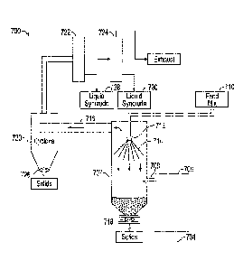
[01071 With reference to FIG. 10, a process 700 comprises a reactor 702 that
is directly heated by
combustion gases supplied from burner 704 in combustion chamber 706 through
duct 708. Feed
mixture 710 can be prepared, for example, as described herein with reference
to FIGs. 1, 3, and 7.
The feed mixture 710 is supplied to nozzle 712 and forms a conical spray
pattern 714 in the reactor
702.
[0108] The nozzle 712 is directed downwardly and can be positioned near the
upper end of the
reactor, e.g., 1/3 of the way down from the top of the reactor toward the
bottom. The nozzle 712
is preferably designed and positioned so that the spray pattern 714 avoids
excessive impingement
on the inside surfaces of the reactor 702 that can lead to caking and/or
buildup of solids on the
walls. The feed mixture 710 is thus introduced countercurrently with respect
to the flue gas to
promote mixing and rapid heating to facilitate the conversion and
volatilization of hydrocarbons.
[01091 The pyrolyzate vapor phase exits the reactor 702 together with the
combustion gas and
steam from the feed mixture water into duct 716. The upward flow rate of the
gases in the reactor
702 in some embodiments is sufficiently low to avoid excessive entrainment of
solid particulates.
The solid particulates fall to the bottom of the reactor 702 and can be
periodically and/or
continuously withdrawn, e.g., via rotary valve 718, for disposal and/or
regeneration and recycle to
.. the slurry preparation. Regeneration can be effected in some embodiments by
contacting the solids
with an oxygen containing gas at high temperature to promote combustion of
hydrocarbon residue
and coke from the particles.
[01101 The gases from the reactor 702 in some embodiments are passed into
cyclone 720 for
removal of fines. Fines can be periodically and/or continuously withdrawn from
the cyclone 720,
e.g., via rotary valve 726. The solids-lean gases in some embodiments are then
passed through
condensers 722 and 724. The first condenser 722 preferably condenses
hydrocarbons, which have
a relatively higher boiling point than water, at a temperature above the water
dew point so that the
condensed liquid syncrude 728 has a low water content, e.g., essentially free
of water so that water
separation is not needed. The second condenser 724 preferably condenses the
hydrocarbons and
26
CA 02969662 2017-06-02
WO 2016/090068 PCMJS2015/063582
water and the liquid syncrude 730 that is collected may be processed, if
desired, to separate an oil
phase from a water phase, e.g., by gravity settling, centrifuge, or the like.
The recovered water in
this and any of the other embodiments illustrated herein can, if desired, be
recycled for preparation
of the feed mixture. Noncondensable gases are recovered overhead from the
condenser 724.
[0111] In embodiments, the pyrolysis chamber or reactor comprises a turbulent
environment. In
embodiments, the pyrolysis chamber or reactor comprises less than about 1 vol%
oxygen, or less
than about 0.1 vol% oxygen, if any is present at all. Accordingly, in
embodiments, the vaporous
effluent comprises less than or equal to about 1 vol% oxygen (i.e., diatomic
oxygen), or less than
about 0.1 vol% oxygen, or is essentially free of oxygen.
[0112] In embodiments, the vaporous effluent comprises less than or equal to
about 98 wt%, or 95
wt%, or 90 wt%, or 80 wt% of the water originally present in the feed mixture,
and/or greater than
70 wt% of the oil originally present in the feed mixture and/or which is added
to the process.
Accordingly, water is consumed in these embodiments of the process.
[0113] In embodiments, the vaporous effluent of the indirectly heated
pyrolysis reactor comprising
the catalytic pyrolysis product comprises less than 10 wt%, or less than 5
wt%, or is essentially
free, i.e., contains less than 1 wt%, of non-condensable gas, for example,
diatomic nitrogen, Ci-C4
hydrocarbons, oxygen, and the like. In embodiments, the vaporous effluent of
the directly heated
pyrolysis reactor comprising the catalytic pyrolysis product and the
combustion gases or other
heating gas, comprises less than 10 wt%, or less than 5 wt%, or is essentially
free, i.e., contains
less than 1 wt%, of non-condensable gas selected from Ci-C4 hydrocarbons.
Preferably less than
5 wt%, or less than 4 wt% or less than 3 wt% or less than 2 wt% or less than 1
wt% of the heavy
oil is converted into C -C4 hydrocarbons,
[0114] Catalytic pyrolysis according to embodiments disclosed herein provides
for greatly
reduced energy requirements and produces catalytic pyrolysis oil products
having superior
properties relative to other methods of crude oil production. In addition,
residual heat can also be
utilized by solvent/heat flooding at the formation to achieve increased
production and superior
quality aspects unrealized in other forms of oil production.
[0115] While not wishing to be bound by theory, it is believed that the
relatively low temperatures
and low pressures of embodiments disclosed herein achieve a reduction in the
long chain carbon
27
CA 02969662 2017-06-02
WO 2016/090068 PCMJS2015/063582
compounds while minimizing and/or avoiding the formation of various non-
condensable gaseous
products (i.e., Ci -C4) and impurities such as sulfur and nitrogen compounds
commonly found in
the product of pyrolysis processes known in the art.
[0116] Catalytic pyrolysis oil products obtained when a heavy oil is processed
according to
embodiments disclosed herein include various mid-or medium fractions having
from about 12 to
about 30 carbons, and various light oil fractions having from about 6 to 12
carbons.
[0117] In embodiments, the mass of the catalytic pyrolysis oil product
recovered from the process
is greater than about 50 wt% of the mass of the oil originally present in the
feed mixture. In
embodiments, the amount of catalytic pyrolysis oil product recovered from the
process is greater
.. than or equal to about 60 wt%, or 70 wt%, or 80 wt%, or 90 wt%, or 95 wt%
of the mass of the
heavy oil originally present in the feed mixture. In embodiments, the
catalytic pyrolysis oil product
recovered from (produced by) the process has a low organic nitrogen content,
(i.e., less than about
1 wt%) and/or low organic or elemental sulfur content (i.e., less than about 1
wt%).
[0118] In embodiments, the heavy oil has an API gravity of less than 22.3 or
less than 20 , and
the catalytic pyrolysis oil product has an API gravity of greater than 22.3
or greater than 20 ,
respectively. In embodiments, the catalytic pyrolysis oil product may be
characterized by
asphaltenes having a higher solubility in the catalytic pyrolysis oil product
than in the heavy oil at
the same temperature.
[0119] In embodiments, asphaltenes have a higher solubility in the catalytic
pyrolysis oil product
recovered from (produced by) the process compared to the solubility of
asphaltenes in the heavy
oil present in the feed mixture. In embodiments, asphaltenes are at least 2
wt% or 5 wt%, or 7
wt%, or 10 wt% more soluble in the catalytic pyrolysis oil product recovered
from (produced by)
the process compared to the solubility of the same asphaltenes in the heavy
oil originally present
in the feed mixture. This allows the catalytic pyrolysis oil product to be
used as a diluent with
.. heavy oil, e.g., from 5 to 100 parts by weight pyrolysis oil to 100 parts
by weight heavy oil, to
transport the heavy oil without requiring heating, or requiring a lesser
degree of heating than
otherwise required, to maintain flowability of the heavy oil.
[0120] The catalytic pyrolysis oil product produced by the instant process may
be characterized
relative to the heavy oil by a transformation of heavy oils into mid and light
crude oils due, at least
28
CA 02969662 2017-06-02
WO 2016/090068 PCMJS2015/063582
in part, to the availability of free H2 and/or CO in the presence of the solid
catalyst during the
pyrolysis. It is believed that the H2 and/or CO reacts with electron deficient
carbons produced in
the pyrolysis chamber when aromatic rings and/or bonds present in heterocyclic
moieties
dissociate during pyrolysis.
[0121] Accordingly, it is believed that the excellent results achieved by the
instant process are due
to a pyrolysis process simultaneously conducted with a catalytic process.
These combined
processes utilize a combination of the gas water shift reaction, hydrocarbon
pyrolysis, and/or
decomposition of water molecules induced by the temperature and promoted by
the catalyst system
to obtain the catalytic pyrolysis oil products, which are mainly comprised of
aliphatic compounds,
low carbon aromatic compounds, and paraffinic compounds, and which have a
substantial
reduction of heteroatoms e.g., nitrogen and sulfur, relative to the heavy oil
utilized as the starting
materials. As a result, the catalytic pyrolysis oil products produced
according to some
embodiments of the instant disclosure comprise a high, nearly aliphatic
stoichiometric ratio of H
to C, and further comprise a substantial viscosity reduction relative to the
heavy oil present in the
feed mixture.
[0122] With reference to FIG. 11, in embodiments according to the invention,
the effluent gas 802
from any one of the pyrolysis reactors described herein (cf. FIGs. 4-10),
e.g., the pyrolyzate vapor
phase, optionally including steam and/or combustion gases and/or
noncondensable gases,
especially steam one or both of carbon dioxide and noncondensable
hydrocarbons, may be
pressurized to injection pressure in compressor 804. In a particular
embodiment, the fines may be
removed before compression, as shown in FIG. 9, for example. The pressurized
treatment fluid is
then injected into injection well 806 proximate to a production well 808, at a
temperature, a
pressure, and in an amount sufficient to produce a flow of hydrocarbons 810
toward the production
well 808. In an additional or alternative embodiment, the recovered oil 812
from any one of the
pyrolysis reactors described herein (cf. FIGs. 4-10), may be pressurized to
injection pressure in
pump 814.
[0123] The effluent gas 802 and/or recovered oil 812, or a component thereof,
may be used as a
solvent, viscosity modifier, source of heat, steam, carbon dioxide,
noncondensable gas, or the like,
in a heavy oil recovery procedure such as, for example, steam or hot water
flood, solvent flood
29
CA 02969662 2017-06-02
WO 2016/090068 PCMJS2015/063582
(including flooding with a combination of solvent and one or more of steam,
water, carbon dioxide,
noncondensable gas, etc.), cyclic solvent injection (CSI), vapor extraction
(VAPEX), cyclic
production with continuous solvent injection (CPCS1), or the like.
LISTING OF EMBODIMENTS
[01241 Accordingly, the invention provides the following embodiments:
El. A process comprising: feeding to a reactor a feed mixture comprising
100 parts by weight
oil, preferably heavy oil (API<22.3, PREFERABLY API<20)), from about 5 to 100
parts
by weight water, and from about 1 to 20 parts by weight solid catalyst
particulates
comprising a mineral support, preferably an acid-reactive mineral or clay, and
an oxide or
acid addition salt of a Group 3 ¨ 16 metal; and heating the feed mixture in
the reactor at a
temperature, pressure, and for a period of time sufficient to produce a
pyrolyzate vapor
phase at an exit from the reactor condensable to form an oil phase lighter
than the feed
mixture oil.
E2. The process of Embodiment 1 wherein the absolute pressure in the
reactor is from about
I to 1.5 atm.
E3. The process of Embodiment 1, wherein the pyrolyzate vapor phase exits
from the reactor
at a temperature above 200 C.
E4. The process of Embodiment 1 wherein the absolute pressure in the
reactor is from about
1 to 1.5 atm and the pyrolyzate vapor phase exits from the reactor at a
temperature above
200 C.
E5. The process of any one of Embodiments El ¨E4 wherein the pyrolyzate
vapor phase exits
from the reactor at a temperature above 300 C.
E6. The process of any one of Embodiments El ¨ E5 wherein the pyrolyzate
vapor phase exits
from the reactor at a temperature from about 300 C to about 500 C.
E7. The process of any one of Embodiments El ¨ E6 wherein the catalyst
particulates comprise
particulates recovered from a thermal desorption process in which an oil
contaminated
substrate, comprising a peptizable matrix component selected from acid-
reactive clays and
minerals, has been contacted with an acidic reagent to form a peptizate, and
the peptizate
mixed with a combustion effluent gas comprising less than about 1 volume
percent oxygen,
CA 02969662 2017-06-02
WO 2016/090068 PCMJS2015/063582
under turbulent conditions at a temperature above 200 C, to form a light phase
comprising
desorbed oil and a dense phase from which the catalyst particulates are
recovered.
E8. The process of any one of Embodiments El ¨ E7 further comprising:
contacting an oil
contaminated substrate comprising a peptizable matrix component selected from
acid-
reactive clays and minerals, with an acidic reagent to form a peptizate;
mixing the peptizate
with a combustion effluent gas comprising less than about 1 volume percent
oxygen, under
turbulent conditions at a temperature above 200 C, to form a light phase
comprising
desorbed oil and a dense phase; recovering solids from the light phase, the
dense phase, or
a combination thereof; and supplying the recovered solids as the catalyst
particulates in the
feed mixture fed to the reactor.
E9. The process of any one of Embodiments El ¨ E8 wherein the catalyst
particulates or a
component thereof, especially clay, have been acid-treated.
E10. The process of any one of Embodiments El ¨ E9 wherein the catalyst
particulates or a
component thereof (which may be the same or different component as any acid-
treated
component) have been thermally treated at a temperature above 200 C.
Eli. The process of any one of Embodiments El ¨ El further comprising
contacting a pre-
catalyst material, preferably clay, with an acidic reagent to acid-treat the
pre-catalyst
material, and supplying the acid-treated material in the catalyst
particulates.
E 12. The process of any one of Embodiments El ¨ Ell further comprising
thermally activating
a pre-catalyst material (which may be the same (before or after acid
activation) or different
material as any acid-treated material) at a temperature above 200 C, and
supplying the
thermally treated material in the catalyst particulates.
E13. The process of any one of Embodiments El ¨ El2 wherein the catalyst
particulates
comprise calcium sulfate, barium sulfate, calcium carbonate, or a combination
thereof.
E14. The process of any one of Embodiments El ¨ El3 wherein the catalyst
particulates
comprise a feldspar mineral, quartz, or a combination thereof.
E15. The process of any one of Embodiments El ¨ El4 wherein the catalyst
particulates
comprise plagioclase feldspar comprising a molar average albite fraction of at
least 0.65
and an overall composition according to the formula
NaAbCai1_Abykl(1+Ab)S1(3_Ab)08, wherein
31
CA 02969662 2017-06-02
WO 2016/090068 PCMJS2015/063582
Ab is a number from 0.65 to 1.0 representing the average fraction of the
albite in the
feldpsar.
E16. The process of any one of Embodiments El ¨ EIS wherein the catalyst
particulates
comprise clay.
E17. The process of any one of Embodiments El ¨ E16 wherein the catalyst
particulates
comprise bentonite.
E18. The process of any one of Embodiments El ¨ E17 wherein the metal
comprises iron, lead,
zinc, or a combination thereof.
E 19. The process of any one of Embodiments El ¨ El8 wherein the metal
comprises a transition
metal.
E20. The process of any one of Embodiments El ¨ E19 wherein the metal
comprises iron, nickel,
cobalt, or a combination thereof.
E21. The process of any one of Embodiments El ¨ E20 wherein the metal
comprises iron (III),
preferably FeCl3.
E22. The process of any one of Embodiments El ¨ E21 wherein the feed mixture
comprises
from about 20 to about 50 parts by weight of the water.
E23. The process of any one of Embodiments El ¨ E22 wherein the feed mixture
comprises
from about 5 to about 10 parts by weight of the catalyst particulates.
E24. The process of any one of Embodiments El ¨ E23 wherein the feed mixture
comprises
from about 20 to about 50 parts by weight of the water, and from about 5 to
about 10 parts
by weight of the catalyst particulates.
E25. The process of any one of Embodiments El ¨ E24 further comprising first
mixing the feed
(heavy) oil and the catalyst particulates, and then mixing the water with the
mixture of the
feed (heavy) oil and catalyst particles to obtain the feed mixture.
E26. The process of any one of Embodiments El ¨ E25 further comprising passing
(e.g.,
pumping) the feed mixture through a line to the reactor.
E27. The process of any one of Embodiments El ¨ E26 wherein the feed mixture
comprises an
emulsion having an electrical stability of greater than 1600 V, when
determined according
to API 13B-2 at 130 C.
32
CA 02969662 2017-06-02
WO 2016/090068 PCMJS2015/063582
E28. The process of any one of Embodiments El ¨ E27 wherein the feed mixture
comprises an
emulsion having an apparent viscosity at 30 C and 100 s-1 at least 30% lower
than the feed
mixture (heavy) oil alone.
E29. The process of any one of Embodiments El ¨ E28 wherein the feed mixture
heating
comprises passing the feed mixture in heat exchange relationship with a
combustion gas.
E30. The process of any one of Embodiments El ¨ E29 wherein the feed mixture
heating
comprises passing the feed mixture in indirect heat exchange relationship with
a heating
medium supplied at an inlet temperature from about 600 C to about 1200 C.
E31. The process of any one of Embodiments El ¨ E30 wherein the feed mixture
heating
comprises passing the feed mixture in direct heat exchange relationship with a
combustion
gas comprising less than about 1 vol% molecular oxygen and having an inlet
temperature
from about 300 C to about 1200 C.
E32. The process of any one of Embodiments El ¨ E31 wherein the feed mixture
oil has an API
gravity less than 22.3 and the pyrolyzate vapor phase comprises a condensate
upon
cooling having an overall API gravity higher than 22.3 .
E33. The process of any one of Embodiments El ¨ E32 further comprising cooling
the
pyrolyzate vapor phase to form a condensate, and collecting the condensate,
wherein the
condensate has an overall API gravity greater than 22.3 .
E34. The process of any one of Embodiments El ¨ E32 wherein asphaltenes from
the feed
mixture (heavy) oil have a higher solubility at a temperature of 30 C in
hydrocarbons
condensed from the pyrolyzate relative to the heavy oil.
E35. The process of any one of Embodiments El ¨ E34 wherein the pyrolyzate
vapor phase
comprises hydrocarbons in an amount recoverable by condensation at 30 C of at
least about
70 parts (preferably 80 parts, more preferably 90 parts) by weight per 100
parts by weight
of the feed mixture (heavy) oil.
E36. The process of any one of Embodiments El ¨ E35 wherein the pyrolyzate
vapor phase
comprises less than 5 vol% of non-condensable (30 C) hydrocarbon gases based
on the
total volume of hydrocarbons in the pyrolyzate vapor phase (dry basis).
E37. A process comprising: preparing catalyst particulates comprising a
mineral support and an
oxide or acid addition salt of a Group 3 ¨ 16 metal, the preparation
comprising contacting
33
CA 02969662 2017-06-02
WO 2016/090068 PCMJS2015/063582
a first pre-catalyst material with an acidic reagent to acid-treat the pre-
catalyst material,
and thermally activating at a temperature above 200 C a second pre-catalyst
material,
which may be the same as the first pre-catalyst material before or after the
acid activation,
or which a different material from the first acid-treated material, and if the
first and second
pre-catalyst materials are different, combining the first and second pre-
catalyst materials,
to form the catalyst particulates; feeding to a reactor a feed mixture
comprising 100 parts
by weight oil, preferably heavy oil (API<22.3, preferably API<20)), from about
5 to 100
parts by weight water, and from about 1 to 20 parts by weight solid catalyst
particulates
comprising a mineral support and an oxide or acid addition salt of a Group 3 ¨
16 metal;
and heating the feed mixture in the reactor at a temperature, pressure, and
for a period of
time sufficient to produce a pyrolyzate vapor phase at an exit from the
reactor condensable
to form an oil phase lighter than the feed mixture oil.
E38. The pyrolyzate vapor phase produced according to the process of any one
of Embodiments
El ¨E37.
E39. The pyrolyzate vapor phase condensate produced according to the process
of any one of
Embodiments El ¨ E39.
E40. An oil produced by heating a feed mixture comprising a heavy oil and a
catalyst system
comprising water and a solid catalyst, in a pyrolysis chamber at a pressure
from about 1 to
1.5 atm for a period of time sufficient to form a vaporous effluent at a
temperature from
about 300 C to about 500 C comprising a catalytic pyrolysis product oil and
steam; and
condensing the vaporous effluent to recover the catalytic pyrolysis product
oil.
E41. An apparatus for treating heavy oil comprising: an oil source, preferably
a heavy oil
(API<22.3, preferably API<20)) source; a water source; a catalyst particulate
source,
wherein the catalyst particulates comprise a mineral support and an oxide or
acid addition
salt of a Group 3 ¨ 16 metal; a mixing zone to combine 100 parts by weight of
the heavy
oil, from about 5 to 100 parts by weight water, and from about 1 to 20 parts
by weight solid
catalyst particulates into a feed mixture comprising an emulsion; a transfer
line to supply
the emulsion from the mixing zone to a pyrolysis zone; a combustion gas source
to supply
a combustion gas to heat the pyrolysis zone; a control system to maintain the
pyrolysis
34
CA 02969662 2017-06-02
WO 2016/090068 PCMJS2015/063582
zone at a temperature, pressure and residence time to form a pyrolyzate vapor
phase; and
a vapor line to receive the pyrolyzate vapor phase from the pyrolysis zone.
EXAMPLES
[0125] Catalyst materials: Catalyst materials according to the present
invention and comparative
catalyst materials were used in the following examples. The inventive solid
catalyst materials were
derived from oil-based drill cuttings (OBDC) comprising an average of 12 wt%
oil, 12 wt% water
and 76 wt% solids, by weight of the OBDC, which were chemically and thermally
treated, and
obtained as the low oil solids recovered from the second reactor ("CAT-A") or
the fines obtained
from the effluent solids cyclone separator ("CAT-B"), according to the process
disclosed in US
8,641,895. To produce the solid catalyst, OBDC were pretreated at 11 metric
tons per hour in the
first reactor (peptizer) with concentrated sulfuric acid at 2 percent by
weight based on the weight
of the OBDC to obtain a peptizate at 85 C, having a pH between 6 and 7.5,
which was fed to the
second reactor (desorber) where it was mixed with hot oxygen-lean combustion
gas at 10000 -
1100 C, i.e., fuel rich combustion to produce a low oxygen combustion gas, to
obtain an operating
.. temperature at the outlet end of the second reactor of 280 - 300 C. CAT-A
contained 1.5 wt%
hydrocarbon and 1.5 wt% water. CAT-B contained 2 wt% hydrocarbon and 5 wt%
water. The
solid catalysts were subject to XRD and microscopic analysis and
characterization. The leachate
metal composition and crystallographic properties are shown in Table 1.
CA 02969662 2017-06-02
WO 2016/090068 PCMJS2015/063582
Table 1
CATALYST: CAT-A CAT-B
Element Selected XRD Elemental Composition,
Solid Phase (wt% total solid)
Si 11.55 11.54
Ba 10.02 15.56
Ca 11.26 8.34
3.84 4.1
Al 3.98 4.25
Fe 3.25 3.91
Mg 1.22 1.27
Na 1.21 0.59
1.12 1.03
Sr 0.91 0.93
Pb 0.27 0.57
Mineral Crystalline Phase Components
(wt% crystal phase)
BaSO4 17 15
SiO2 8 4
CaCO3 27 16
CaSO4 8 4
Albite 40 64
Mineral Crystal Size
BaSO4 0.5 -45 ium 0.5 - 45 !um
SiO2 37 - 500 pm 37 - 45 lam
CaCO3 45 - 100 1.tm 45 - 100 gm
CaSO4 1 - 37 lam 1 - 10 ..tm
Albite 0.25 - 350 1,tm 0.25 - 35 i.tm
[0126] Samples of CAT-A and CAT-B were calcined at 580 C to produce CAT-A2 and
CAT-B2,
respectively. CAT-A2A was obtained by heating CAT-A to 100 C and holding the
temperature
for 20 minutes, followed by heating to 150 C and holding for 60 minutes, and
then heating to
700 C at 5 C/min and holding at 700 C for 3 hours.
[0127] CAT-A3 was obtained by washing CAT-A with water and drying prior to use
to investigate
the effect of removing water-soluble salt thought to exist on the surface of
the solid catalyst.
[0128] A sample of the OBDC as received (19.75 wt% water, 16.59 wt% oil) was
washed with
hexane (13.53 wt% water, 3.79 wt% oil) and dried in an oven at 80 C for two
hours to obtain CAT-
36
CA 02969662 2017-06-02
WO 2016/090068 PCMJS2015/063582
D (4.21 wt% water, 3.16 wt% oil). Accordingly, CAT-D was OBDC which were
neither treated
with acid nor thermally processed by peptization/desorption.
[0129] Other comparative particulated catalyst materials used in the following
examples included
ZSM-5 zeolite (Aldrich) ("CAT-C"); bentonite clay (Aldrich) ("CAT-E');
concentrated sulfuric
acid; cobalt metal; nickel metal; molybdenum metal; iron oxide (Fe2O3); and/or
salt (NaCl), all
of which were utilized as purchased without further processing.
[0130] CAT F was obtained by loading Fe(III) on bentonite. The bentonite was
an acid-treated
calcium bentonite and was prepared by mixing the as-received bentonite (100
mesh) with 1 M
aqueous NaCl at a 1:2 weight ratio (1 part by weight bentonite, 2 parts by
weight brine), stirring
for 1 hour and then allowing the mixture to sit for 16-24 hours. The excess
brine was removed and
the bentonite rinsed with 5 parts by weight of distilled water per 1 part by
weight bentonite. The
excess water was removed, the bentonite dried at 135 C for 4 ¨6 hours and
ground to pass through
a 40 mesh screen.
[0131] The Fe(III) was prepared by mixing 3 parts by weight 100 mesh carbon
steel shavings with
1 part by weight aqua regia (1 part by weight nitric acid, 3 parts by weight
hydrochloric acid, 2
parts by weight water) with constant stirring. Two additional aliquots of aqua
regia (1 part by
weight each) were added and the temperature increased to 95 C. The slurry was
filtered, the
recovered solids dried in an oven at 100 C, ground to pass a 100 mesh screen,
and slurried at 1
part by weight oxidized iron in 24 parts by weight distilled water. Then 2
parts by weight of the
Fe(III) slurry were mixed with 3 parts by weight of the dried 40 mesh
bentonite, the resulting slurry
dried to 400 C for 2 hours in an oven, and the solids cooled and ground to
pass 60 mesh screen.
[0132] Metals Composition of CAT-A, CAT-A2, CAT-B, CAT-B2: The solid catalysts
materials
were further analyzed for various metals using microwave assisted acid
digestion of siliceous and
organically based matrices coupled with inductively coupled plasma-atomic
emission
spectrometry according to EPA 3052/6010. The results are shown in Table 2.
37
CA 02969662 2017-06-02
WO 2016/090068 PCMJS2015/063582
Table 2. Relative amounts of metals EPA 3052/6010
Element CAT-A CAT-A2 CAT-B CAT-B2 CAT-D
calcined calcined
(mg/kg) (mg/kg) (mg/kg) (mg/kg) (mg/kg)
Cd 2 2 2.8 2.7 2
Pb 413.04 448.45 553.33 632.36 734.39
Ag 2.43 5.01 3.18 3.91 2
Cr 41.96 44.64 31.38 34.87 35.31
Cu 79.17 85.99 108.00 104.01 94.59
Fe 21314.46 21001.00 15353.85 14108.22 13510.2
Sn <10.00 <10.00 <10.00 <10.00 <10.00
Zn 376.14 388.39 558.67 564.13 195.92
Bi <10.00 <10.00 <10.00 <10.00 <10.00
[0133] As these data show, the metals composition of the solid catalyst
samples and the untreated
CAT-D were similar regardless of the thermal processing history. These data
also show very little
difference between the calcined samples CAT-A2 and CAT-B2 and the non-calcined
samples
CAT-A and CAT-B. Comparison of CAT-A with CAT-B (the larger particulates vs.
the fines)
shows an increase in the concentrations for lead, silver, copper and zinc of
30-45 % in the fines
(CAT-B), and a decreases of nearly 25 % in iron and chromium in the fines (CAT-
B) relative to
the larger particles (CAT-A). The same is true for the corresponding calcined
samples. These
data further show that the majority metallic element is iron. Although not
bound by theory, the
.. changes in composition of the treated solids (CAT-A, CAT-B) relative to the
untreated OBDC
(CAT-D) may be at least partially responsible for the enhanced catalytic
effects exhibited for
recovery of upgraded hydrocarbons from heavy oil, as described below.
[01341 Additional testing was conducted on two other samples of CAT-A and CAT-
B, prepared
as discussed above. The tests were conducted to determine the concentration of
other trace metals
according to EPA3050MOD/6010, and indicated the additional presence of nickel,
silver, and
vanadium. The results are shown in Table 3.
38
CA 02969662 2017-06-02
WO 2016/090068 PCMJS2015/063582
Table 3. Relative amounts of metals EPA3050MOD/6010
Element CAT-A CAT-A CAT-B CAT-B
wet basis dry basis wet basis dry basis
(mg/kg) (mg/kg) (mg/kg) (mg/kg)
Cd 4.10 4.15 4.50 4.57
Pb 1845.00 1865.52 1617.00
1638.21
Ag 6.40 6.47 6.00 6.10
Cr 38.70 39.13 51.90 52.74
Cu 90.30 91.30 88.40 89.84
Fe 16210.00 16390.29 17870.00 18160.57
Sn <10.00 <10.00 <10.00 <10.00
Zn 587.60 594.14 604.20 614.02
Bi <10.00 <10.00 <10.00 <10.00
Ni 47.10 47.62 49.30 50.10
Ag 6.40 6.47 6.00 6.10
V 24.70 24.97 31.70 32.22
Emulsion Stability and Properties: Feeding of the crude oil emulsion into the
distillation/pyrolysis
apparatus according to embodiments disclosed herein is facilitated by the
ability of the solid
catalyst to readily combine with the heavy oil and/or heavy oil and water to
form a mixture having
reduced viscosity relative to the heavy oil. Mixing the heavy oil with the
solid catalyst reduced
the viscosity to facilitate pumping or otherwise conveying the material at
temperatures well below
those otherwise required to pump the heavy oil. In some instances, for
example, addition of the
solid catalyst to the heavy oil allows for a pumpable mixture at 25 C to about
40 C.
[0135] In embodiments, the solid catalysts are preferably added to the feed
(the heavy oil or the
heavy oil and water) prior to feeding the mixture the pyrolysis apparatus.
Accordingly, the
temperature relation to sample viscosity when combined with varying amounts of
catalyst was
determined.
[01361 The heavy crude oil sample was combined with 5 wt% (oil basis) CAT-A
and varying
amounts of water. The electrical stability (in volts) of the emulsion
according to API 13B-2, and
the viscosity of each mixture was determined at three different temperatures.
The results are
provided in Table 4A.
39
CA 02969662 2017-06-02
WO 2016/090068 PCMJS2015/063582
Table 4A. Emulsion viscosity and stability
Temp. 40 C 130 C 250 C
Water, wt% Viscosity Stability Viscosity Stability Viscosity Stability
Oil basis (mPa-s) (V) (mPa-s) (V) (mPa-s) (V)
0 10480 1818 1652 2000 32 2000
20 8380 1239 256 2000 32 2000
30 7048 712 210 2000 32 2000
40 6264 598 164 1902 32 2000
50 5664 539 158 1680 32 2000
[0137] As these data show, the viscosity of the mixture decreases dramatically
with an increase in
temperature. In addition, the amount of water added to the oil affects both
viscosity and stability
of the emulsion. As these data further show, the most dramatic reduction in
viscosity with the
least amount of change in the stability occurs at a temperature of about 130 C
and a water
concentration of about 20 wt% (oil basis). Accordingly, further tests were
conducted at a water
concentration from about 20 wt% to about 50 wt% (oil basis).
[0138] Testing was conducted to determine the effect of the order of addition
on the final viscosity
of the heavy crude/water/catalyst emulsion. The viscosity of a heavy crude
sample was first
determined. In a first example, 30 wt% water (oil basis) was first added to
the heavy crude and
mixed in a blender for 5 minutes. The viscosity was then determined
(Brookfield, spindle 6 or 7).
Next, 5 wt% CAT-A (oil basis) was added and mixed for 5 minutes. The viscosity
was then
determined. The resulting Emulsion 1 was then allowed to cool to 34 C and the
viscosity
determined again. A second example was conducted except that CAT-A was first
combined with
the heavy crude followed by the water. The reduction in viscosity from heavy
crude adjusted for
temperature was then calculated. These data arc shown in Table 4B.
CA 02969662 2017-06-02
WO 2016/090068
PCMJS2015/063582
Table 4B. Effect of order of addition
Example Order of addition Viscosity End
T ( C) T delta Reduction in
(mPa-s) ( C)
viscosity* (%)
Heavy Crude NA 30,100 32 0 0
1 Water 12560 38 6 29.1
CAT-A 5760 46 8 42.5
Emulsion 1 14480 34 0 41.3
2 CAT-A 6240 46 14 68.4
Water 13280 42 -4 32.8
Emulsion 2 19280 34 0 0
* % reduction in viscosity is relative to the viscosity of the heavy crude at
the same temperature,
as shown in Table 4C; NA = not applicable.
[0139] These data show that slightly lower viscosity is obtained by mixing the
water with the
heavy oil first, and then mixing CAT-A with the oil-water mixture. The
viscosity of a heavy crude
sample and the corresponding Emulsion 1 was determined over a temperature
range from 30 C to
60 C. These data are shown in Table 4C.
Table 4C. Emulsion and heavy crude viscosity vs. tem?erature
Temp. Viscosity Emulsion 1 Viscosity heavy
% reduction in
( C) (mPa-s) crude (mPa-s)
viscosity
30 19,760 35,000 43.5
32 17,920 29,539* 40.4
34 16,080 24,658* 34.8
38 12,400 17,703* 30.0
40 10,560 14,200 25.6
42 9,568 13,140* 27.2
46 7,590 10,020* 24.3
50 5,600 7,200 22.2
60 3,200 4,500 28.8
* The value of the heavy oil viscosity was extrapolated from a power fit of
data acquired at 30, 40,
50 and 60 C according to the power equation viscosity = 9E+08*(temp C)(-
2.979)T; R2 = 0.9984.
[0140] The increase in temperature upon addition was due in part to the
agitation. However, these
data also show an exothermic event upon addition of CAT-A, and it is clear
that the addition of
CAT-A has a pronounced effect on the viscosity even without the addition of
water.
[0141] In the following examples, the heavy oil/catalyst/water mixture was
heated in batch mode
in a retort reactor equipped with a condenser to condense overhead vapors. In
some runs as
indicated, a layer of silica sand was inserted in the bottom of the reactor.
The heavy oil sample
41
CA 02969662 2017-06-02
WO 2016/090068 PCMJS2015/063582
was first mixed with water and the appropriate catalyst and the emulsion
charged into the reactor.
The emulsion was prepared with the indicated proportion of catalyst solids,
total water (added
water plus any water in the oil sample), and oil (net oil in the sample as
adjusted for water and
solids in the heavy oil sample). The reactor was then heated to the indicated
temperatures over the
indicated time period, over which the catalytic pyrolysis product was
condensed, collected and
weighed. The recovery of the oil was based on the total amount of oil
originally present in the
heavy oil sample, corrected for added solids, e.g., solid catalyst and/or
sand. These data are shown
in Table 5.
Table 5
Run Reactor Conditions and Charge Results
Time, T range, Water, Cat. Solids, Other, Oil Net
min C wt%* wt%* wt%* Recovered Residue,
BL 1 70 23-522 0 0 52 25
BL 2 95 23-465 0 0 60 23
1 60 32-513 30 0 72 24.4
2 105 23-500 50 D 5 59 19.4
3 110 23-500 25 A 5 62 22.6
4 100 25-375 50 A 5 81 ND
5 76 25-500 50 A 10 80 ND
6 50 25-375 50 A 5 88 ND
7 91 25-500 25 A2 2.5 SB 74 15.6
8 100 25-500 30 A2A 5 82 17
9 95 25-500 30 A3 5 72 15
100 25-500 50 B 10 81 ND
11 120 25-500 50 B 10 SB 60** ND
12 188 36-275 25 C 2.5 49 35
13 173 25-600 25 C 5 A,0.5 63 27
14 170 25-490 50 C 5 A-, 1 61 ND
15 188 36-275 50 C 5 SB 63 ND
16 95 25-500 30 Fe2O3/ 1/1 70 15
NaCl
17 188 36-275 50 E 5 SB 62 ND
18 95 25-500 50 Co/Ni 1/1 62 ND
19 95 25-500 50 Co/Mo 1/1 61 ND
95 25-500 50 Co 1 62 ND
Notes for Table 5: * All contents wt% oil basis; ** solids built up within the
reactor; BL =
baseline; A- = H2504; SB = sand bed; ND = not determined.
42
CA 02969662 2017-06-02
WO 2016/090068 PCMJS2015/063582
[0142] Baseline run, heavy crude pyrolysis, no water or catalyst added: A
sample of heavy
crude oil (viscosity 31.6 kPa at 25 C; density 0.989 g/cm1) was fed into a
small retort reactor,
equipped with an electric resistance heater and an overhead condenser. The
heater was turned on
and the retort reached a temperature of 500 C after 70 minutes. The oil
recovery was just 52 wt%
in Baseline 1 and 60 wt% in the repeat Baseline 2.
[0143] Run 1 (comparative) - heavy crude pyrolysis, 30 wt% water: An oil/water
emulsion
was prepared by mixing the heavy crude oil with about 30 wt% water, without
any catalyst solids.
The emulsion was fed to the retort reactor which reached a temperature of 500
C after 60 minutes.
The oil recovery improved to 72 wt%.
[0144] Run 2 - heavy crude pyrolysis, 30 wt% water and 5 wt% CAT-D: An
oil/water
emulsion was prepared by mixing 200.10 g of heavy crude oil (viscosity 31.6
kPa at 25 C; density
0.989 g/cm3), 100.23 g of water and 10.30 g of CAT-D. The emulsion (181.17 g)
was fed into the
retort which upon heating reached a temperature of 500 C after 105 minutes. It
was observed that
only water was present in the overhead fractions up to 220 C. The majority of
the oil was
recovered around 350 C. The presence of sulfur was apparent from the dark
color and odor of the
lower temperature fractions. The higher temperature fractions were
progressively darker. These
results were similar to the use of water alone in Run 1, and the oil recovery
was no better than
baseline.
[0145] Runs 3-6 - heavy crude pyrolysis, 25-50 wt% water and 5-10 wt% CAT-A:
In these
runs, heavy crude oil was mixed with CAT-A (5-10 wt%) and water (25-50 wt%),
and placed in
the retort reactor, which, upon heating, reached the temperature indicated
after the specified time
period, over which fractions were collected overhead. In these runs, two
distinctly different cuts
were recovered below 220 C, initially an emulsion and then a light oil,
indicating that CAT-A
promoted the formation of a low boiling point hydrocarbon fraction. The
diminished presence of
sulfur was also apparent relative to the heavy crude oil, as evidenced by the
light yellow oil
collected from the reactor, along with the absence of sulfur odor in the
collected fractions. This is
in sharp contrast to CAT-D, which had essentially no effect on the recovered
oil. Moreover, the
oil recovery in Runs 4-6 was better than with the OBDC (cf. Run 2, 5 wt% CAT-
D, 50 wt% water).
Run 4 with 50 wt% water and 5 wt% CAT-A, showed a dramatic increase in the
amount of oil
43
CA 02969662 2017-06-02
WO 2016/090068 PCMJS2015/063582
recovered (81 wt%) relative to the heavy crude alone and/or heavy crude/water.
Run 5 with 50
wt% water and 10 wt% CAT-A, was comparable to Run 4 even though the quantity
of CAT-A had
been doubled in Run 5. CAT-A exhibited a markedly different behavior as a
catalyst than CAT-
D, with catalytic properties apparently activated by the acid peptizing and/or
the thermal
processing of the OBDC with hot, oxygen-lean combustion gases.
[0146] Runs 7 and 8 - heavy crude pyrolysis, 25-30 wt% water and 2.5 wt% CAT-
A2 or 5
wt% CAT-A2A: Runs 7 and 8 with calcined CAT-A were comparable to Runs 3-6. CAT-
A2A,
calcined at the higher temperature, had better oil recovery than the lower-
temperature calcination
of CAT-A2.
[0147] Run 9 ¨ heavy crude pyrolysis, 30 wt% water and 5 wt% CAT-A3: Washed
CAT-A
showed a slight reduction in recovered oil, thus suggesting a positive effect
when salt is present
and/or added. Accordingly, in embodiments, the solid catalyst further
comprises salt, either
present on the solid catalyst or added to the process.
[0148] Runs 10 and 11 - heavy crude pyrolysis, 50 wt% water and 10 wt% CAT-B:
Run 10[7]
with 50 wt% water and 10 wt% CAT-B, was comparable to Runs 5 and 6, indicating
fmes were
generally equivalent to CAT-A. Run 11[8] was a repeat of Run 10[7] with a bed
of sand placed in
the retort reactor, but the marked reduction of the oil recovered is thought
to have occurred due to
solids build up within the reactor.
[0149] Runs 12-15 - heavy crude pyrolysis with CAT-C: In Run 12, CAT-C
(zeolite) with water
was no better than the heavy crude alone without water. Adding sulfuric acid
or using a sand bed
with CAT-C (Runs 13-15) were no better than pyrolysis with only water and/or
untreated OBDC
added as in Runs 1 and 2.
[0150] Run 16 ¨ heavy crude pyrolysis, water with Fe2O3 and NaCI: Run 16
replaced CAT-
A with NaC1 and Fe2O3, the major components in the solid catalyst according to
the compositional
analysis above. However, the oil recovery results were similar to using water
alone as in Run 1.
[0151] Runs 17-20 ¨ heavy crude pyrolysis, water with other catalysts: Runs 16-
20 with
bentonite clay (CAT-E), cobalt, nickel, and/or molybdenum, were also similar
to pyrolysis of the
heavy oil alone or with water and/or OBDC as in the baseline or Runs 1-2.
Bentonite was selected
44
CA 02969662 2017-06-02
WO 2016/090068 PCMJS2015/063582
as a common drilling fluid additive present in the OBDC, whereas the metals,
nickel, cobalt and
molybdenum, are present in CAT-A.
[0152] As these data show, the inventive examples increase the amount of oil
recovered as
catalytic pyrolysis product from about 60 wt% up to above 80 wt% of the oil
originally present in
oil containing material. Furthermore, water is consumed during the process.
[0153] In embodiments, the instant process produces an oil having greatly
improved properties
when compared to the heavy crude starting material. The physical properties of
the heavy oil and
the catalytic pyrolysis product according to an embodiment (i.e., the overhead
fraction collected
from the pyrolysis reactor in Run 4) arc listed below in Table 6:
Table 6
Property Unit Heavy Oil Run 4 Pyrolyzate
Density /
g, cm 0.977 0.85
Viscosity 6?:// 25 C Pa-s 13.58 - 19 0.020 ¨ 0.30
API gravity API 13 35
Boiling point C 95 >200
Flash point C 66 >90
Aniline point C ND >68
[0134] Mass spectral analysis of the baseline heavy oil, the oil obtained as
the pyrolyzate from
Run 1, and the oil obtained as the pyrolyzate from Run 3, are shown in FIGs.
12, 13, and 14,
respectively. These data show that the catalyst system according to
embodiments of the instant
disclosure produces a transformation of the lighter hydrocarbons into heavier
hydrocarbons
through catalysis, pyrolysis and possibly hydrogenation due to the gas shift
reaction involving the
water. These data show a decrease in the concentration of both lighter and
heavier hydrocarbons
relative to the heavy crude, with a corresponding increase in the
concentration of hydrocarbons in
the C8 to C15 range. Accordingly, these data suggest that the catalyst system
is responsible for
converting both low and high molecular weight hydrocarbons into mid-range
hydrocarbons thus,
lowering the viscosity and improving the properties of the recovered oil
relative to the heavy crude.
10/55] Saturates, Aromatics, Resins and Asphaltenes (SARA) Testing: These
tests are performed
on a crude oil and the pyrolyzate obtained from a mixture of 100 parts by
weight of the crude oil,
parts by weight water, and 5 parts by weight of a CAT-A sample in the manner
described for
CA 02969662 2017-06-02
WO 2016/090068 PCMJS2015/063582
Run 4 above. These tests were performed on a mixture of 100 parts by weight
heavy oil, 30 parts
by weight water, and 5 parts by weight of a CAT-A sample. As seen in Table 7,
the pyrolyzate had
lower levels of resins and asphaltenes, and higher levels of aromatics.
Table 7
SARA Component Crude Oil CAT-A/Water
Pyrolyzate
Saturates, wt% 56.2 55.4
Aromatics, wt% 12.0 36.1
Resins, wt% 22.4 8.0
Asphaltenes, wt% 9.4 0.5
[0156] Thermogravimetric, Calorimetric and Micropyrolysis Tests: These tests
are performed on
a mixture of 65 parts by weight heavy oil, 30 parts by weight water, and 5
parts by weight of a
CAT-A sample. Thermogravimetric analysis confirms more volatiles are released
by the mixture
than the base heavy oil alone. Differential scanning calorimetry shows a large
exotherm upon
continued heating the mixture above the boiling point of water, indicative of
an exothermic
chemical reaction, whereas the baseline heavy crude oil does not.
Micropyrolysis similarly
confirms that yields of C8 - C18 alkanes from the heavy oil/CAT-Alwater
mixture are markedly
increased relative to the heavy oil alone, whereas a very low level of lighter
hydrocarbons are
observed for the mixture and a very high level for the heavy oil alone.
[0157] Thermal Tests with Aqueous CAT-F Slurry (No Oil): A laboratory bench
scale reactor was
used in this test of a slurry of 5 parts by weight CAT-F mixed in 30 parts by
weight water. The
reactor was externally (indirectly) heated by combustion flue gas flowing
around the outside of
the bottom of the enclosed reactor. An outlet pipe from the reactor was
connected to a condenser
for collection of a condensate from a drain into a collection flask and
collection of noncondensable
gases from an outlet into a plastic bag. The heater was turned on to heat the
reactor, and the heater
output was unchanged throughout the duration of the test. The sealed reactor
heated up to a
temperature of 480-500 C and no further temperature increase was observed.
[0158] The Cat-F slurry was then injected at ambient temperature from a
pressurized tank (2
kg/cm2) into a nozzle pointed downwardly into the reactor and positioned 1/3
of the way from the
top toward the bottom of the reactor. in one run, the slurry injection rate
was 6.7 mL/min and the
46
CA 02969662 2017-06-02
WO 2016/090068 PCMJS2015/063582
temperature at the top of the reactor gradually increased 50 C over a period
of 12 minutes and a
noncondensable gas was collected in the bag. The collected gas tested positive
for flammability
when a small stream squirted out of the bag through a nozzle toward a yellow
hydrocarbon flame,
as indicated by travel of the flame up the stream toward the bag; and a change
in the color of the
flame from yellow to bluish white suggested the presence of hydrogen or
another highly flammable
gas.
[01591 In other tests at higher slurry injection rates of 7.2 mL/min for 14
minutes, and 20 mL/min
for 21 minutes, the temperature rose more slowly (7.2 mL/min) or decreased (20
mL/min),
respectively. These results show that there was an exothermic catalyst and/or
water-catalyst
reaction that generated a flammable gas, and suggest hydrogen may be evolved
in situ in processes
employing CAT-F and water according to some embodiments of the invention.
[0160] Steady State Pyrolysis Tests: These tests used a pilot plant scale
reactor in accordance with
the direct-heating design shown in FIG. 10, except that only one exchanger
downstream from the
cyclone was used and there was no solids discharge from the reactor so solids
accumulated in the
bottom of the reactor during the test. The reactor was heated by combustion
flue gas flowing into
the side of the reactor near the bottom. A slurry injection nozzle pointed
downwardly
(countercurrent to the flue gases) was positioned 1/3 of the way from the top
of the reactor toward
the bottom to provide a conical spray pattern. The reactor was equipped with
thermocouples in the
combustion chamber, within the reactor, at the top of the reactor, and in the
cyclone.
[0161] An emulsion of heavy crude (API < 10 ) was prepared by heating the
crude oil to 70 C,
adding water and mixing with an overhead mixer for 10 minutes, then adding the
catalyst
particulates and mixing for another 5 minutes. The resulting emulsion was
composed of 5 parts by
weight catalyst particulates, 30 parts by weight water (added water plus water
in heavy oil sample),
and 65 parts by weight oil (heavy oil less water and solids). The reactor was
brought to steady state
at a reactor temperature between 400 C and 600 C, while maintaining the
combustion at a steady
rate between 1100 C and 1200 C, adjusting the emulsion feed rate as necessary
to obtain the
desired temperatures, and collecting the pyrol yz ate liquids from the
condenser.
[01621 Typical operating conditions for these tests using emulsions made with
CAT-A are shown
in FIG. 15. In the case shown, the reactor temperature was maintained
generally between 400 C
47
CA 02969662 2017-06-02
WO 2016/090068 PCMJS2015/063582
and 600 C, the reactor outlet temperature was generally between 300 C and 400
C, and the
cyclone temperature was between 200 C and 300 C. Note the slurry feed rate
dropped to 0
whenever the injection nozzle plugged temporarily. The reactor was heated up
to operating
temperature with combustion gases only before the slurry feed was started (not
shown), and then
the temperature of the reactor slowly declined until steady state was reached
with the temperature
near 400 C after 1-2 hours. Increasing the slurry feed rate from near 400 mL/h
to 600 mL/h
increased the reactor temperature, indicating a reaction exotherm.
[0163] When the feed slurry was prepared using CAT-F with the heavy oil and
water, and fed to
the pilot plant reactor, the recovered oil was a low viscosity, low-density
(API > 30 ) liquid
representing a recovery of 90 wt% of the oil from the slurry, while non-
condensable gases
represented just 4 wt% of the oil in the slurry. This compared favorably to
the typical recovery of
80-85 wt% of the oil when CAT-A was used.
[0164] The invention has been described above with reference to numerous
embodiments and
specific examples. Many variations will suggest themselves to those skilled in
this art in light of
the above detailed description. All such obvious variations are within the
full intended scope of
the appended claims.
48