Sélection de la langue

Search

Sommaire du brevet 2969682 

Énoncé de désistement de responsabilité concernant l'information provenant de tiers

Une partie des informations de ce site Web a été fournie par des sources externes. Le gouvernement du Canada n'assume aucune responsabilité concernant la précision, l'actualité ou la fiabilité des informations fournies par les sources externes. Les utilisateurs qui désirent employer cette information devraient consulter directement la source des informations. Le contenu fourni par les sources externes n'est pas assujetti aux exigences sur les langues officielles, la protection des renseignements personnels et l'accessibilité.

Disponibilité de l'Abrégé et des Revendications

L'apparition de différences dans le texte et l'image des Revendications et de l'Abrégé dépend du moment auquel le document est publié. Les textes des Revendications et de l'Abrégé sont affichés :

  • lorsque la demande peut être examinée par le public;
  • lorsque le brevet est émis (délivrance).
(12) Demande de brevet: (11) CA 2969682
(54) Titre français: DISPOSITIF MANUEL D'IRRIGATION DE LA CAVITE BUCCALE
(54) Titre anglais: HANDHELD ORAL IRRIGATOR
Statut: Réputée abandonnée et au-delà du délai pour le rétablissement - en attente de la réponse à l’avis de communication rejetée
Données bibliographiques
(51) Classification internationale des brevets (CIB):
  • A61M 3/02 (2006.01)
  • A61C 17/02 (2006.01)
(72) Inventeurs :
  • KUTYEV, ANATOLY ANATOLYEVICH (Fédération de Russie)
(73) Titulaires :
  • ANATOLY ANATOLYEVICH KUTYEV
  • ANDREY VASILYEVICH KONIN
(71) Demandeurs :
  • ANATOLY ANATOLYEVICH KUTYEV (Fédération de Russie)
  • ANDREY VASILYEVICH KONIN (Fédération de Russie)
(74) Agent: BORDEN LADNER GERVAIS LLP
(74) Co-agent:
(45) Délivré:
(86) Date de dépôt PCT: 2014-12-04
(87) Mise à la disponibilité du public: 2015-06-11
Requête d'examen: 2019-12-04
Licence disponible: S.O.
Cédé au domaine public: S.O.
(25) Langue des documents déposés: Anglais

Traité de coopération en matière de brevets (PCT): Oui
(86) Numéro de la demande PCT: PCT/RU2014/000905
(87) Numéro de publication internationale PCT: RU2014000905
(85) Entrée nationale: 2017-06-02

(30) Données de priorité de la demande:
Numéro de la demande Pays / territoire Date
2013154165 (Fédération de Russie) 2013-12-06

Abrégés

Abrégé français

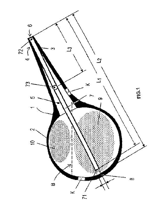
L'invention vise à assurer à la sortie de la buse d'un dispositif d'irrigation un jet de gaz et liquide interrompu qui favorise un nettoyage efficace tout en assurant une grande simplicité d'utilisation. On a inséré à l'intérieur de la bouteille (1) un aérateur se présentant comme un élément en forme de tube (7) possédant des extrémités ouvertes (71, 72) et une zone de perforation (73) dans la paroi latérale de l'élément (7) formé par au moins un orifice. L'extrémité de l'élément en forme de tube (7) du côté de l'extrémité ouverte est disposée librement dans l'espace de la bouteille (1) et son extrémité (71) est disposé avec un certain intervalle par rapport au fond de la bouteille.


Abrégé anglais

The invention is directed to providing, at the exit from the nozzle of an irrigator, an intermittent gas-liquid jet for enabling effective cleaning, while being easy to use. A bulb (1) has an aerator introduced therein which is in the form of a tubular element (7) with open tips (71, 72) and a perforation region (73) in the side wall of the element (7), said region being comprised of at least one hole. The end of the tubular element (7) on the open-ended side is freely disposed in the cavity of the bulb (1), and the tip (71) is disposed with clearance from the base of the bulb.

Revendications

Note : Les revendications sont présentées dans la langue officielle dans laquelle elles ont été soumises.


6
CLAIMS:
1. Irrigator comprising a pear-shaped bulb for the liquid with elastic walls
comprising on its
tapered end a tip connected by a through-channel to a jet nozzle,
characterized in that an aerator is comprised in the bulb constituting a
tubular element
with open butts and a perforated area in the side surface of the element
formed by at least
one orifice,
one end of the tubular element from the side of the open butt being leak-proof
fixed in the
through-channel of the tip in the manner that its butt is open towards inside
of the jet
nozzle, the other end of the tubular element being installed loosely in the
cavity of the
bulb with a gap with respect to the bulb bottom, and the perforated area in
the tubular
element side wall being located inside the bulb cavity adjacent to the tip
tapered end.
2. Irrigator as per Claim 1, characterized in that the tubular element is
embodied integrated
with the tip.
3. Irrigator as per Claim 1, characterized in that the size of the
perforated area constitutes
0.05 ... 0.6 of the flow cross-section of the tubular element.
4. Irrigator as per Claim 1, characterized in that the length of the
tubular element constitutes
0.75 ... 0.98 of the distance between the bottom and the jet nozzle along the
irrigator
symmetry axis.

7
5. Irrigator as per Claim 1, characterized in that it comprises a back-flow
valve installed in
the bulb wall and embodied in the manner providing additional filling the bulb
cavity
with air and/or liquid when recovering its shape on bulb release.

Description

Note : Les descriptions sont présentées dans la langue officielle dans laquelle elles ont été soumises.


CA 02969682 2017-06-02
1
HANDHELD ORAL IRRIGATOR
FIELD OF THE INVENTION
The invention relates to the medical instruments, namely, to irrigators, and
may be employed for
hygienic procedures in clinical and domiciliary.
PRIOR ART
The proper hygiene of the oral cavity, teeth and gingivae is known to inhibit
development of
recalcitrant periodontitis and periodontosis. Intensive tooth-washing
following routine cleaning
procedures using a tooth-brush favors removal of food residues, pathogenic
germs and other
infection-producing components. Known are efficient electronic gadgets for
oral cavity irrigator,
in particular, that of Waterpik Technologies (USA), employing bubble
technology of delivered
jet saturation, however, they are featured with a rather complicated design.
A handheld irrigator is known (W02011105644 (Al), Y00 B YUNG EUN, 01.09.2011),
comprising a pear-shaped rubber bulb with elastic walls and jet nozzle tip
connected to the
nozzle through-channel with a tube submerged inside the bulb down to its
bottom. However, this
irrigator is designed to prevent bulb filling through the nozzle, which is
implemented by means
of a separate piston pump. Moreover, the irrigator is only intended for caval
organ filling with a
liquid, without arranging washing thrust. A handheld oral irrigator is
described (DE3146729
(Al), AHSBAHS, 07.07.1983), comprising a jet nozzle connected to the tube
immersed into a
vessel with liquid and a liquid jet interrupter, however, not employing liquid
aeration.
An irrigator is known (RU2018323 Cl, Ma3eTos gp., 30.08.1994) comprising a
mixer for
cleaning liquid and gas generating a gas-liquid medium at the jet nozzle
output. The mixer
comprises an olive-shaped caval chamber with a central nozzle, a hose, and a
gas/air delivery
device. The caval chamber in the central nozzle area comprises a tangential
nipple for gas
delivery device connection, a part of the central nozzle being located within
the inner volume of
the caval cavity. However, this irrigator is featured with a complicated
design and is not intended
for using in household and field conditions.

CA 02969682 2017-06-02
2
Known from the application (DE19527943 (Al), KERPLAS NEUENBURG GMBH KUNSTST,
20.02.1997) is a device for delivery gas-liquid medium implemented as an
elastic bulb rot the
liquid with a tube located therein and connected with a jet nozzle installed
at the spout. Liquid
delivery from the spout is effected at bulb pressing by hand. However, in this
device nozzle and
tube inner diameter are selected basing on condition of generating of a finely
pulverized spray
featured by low mechanical impact.
An oral irrigator is known (09321856 (Al), POGLIANI, GRIMOLDI, 11.1 1.1993),
wherein a
pulsing liquid jet is generated through using of a jet modulating valve for
the liquid outflowing
from the bulb pressurized with compressed gas. However, it requires a stock of
disposable bulbs,
providing no possibility of bulb recharging with the required medium. There
are also other oral
cavity handheld irrigators described in (US4286735 (A), SNEIDER, 1981-09-01;
EP0592082
(B1), NOVADENT LTD, 13.01.1999; BRPI1105928 (A2), DA SILVA HERNANDES,
10.09.2013).
The easiest and the most affordable irrigator for washing of organism canals
and cavities is a ball
syringe constituting a rubber pear-shaped bulb with elastic walls and soft or
rigid tip possessing a
through-channel with a jet nozzle suitable for conducting liquid into and out
of the bulb
(Kabatov, Yu.F., Medical instruments, hardware, and equipment. ¨ Moscow,
"Meditsina", 1977,
pp. 70 to 73 (in Russian); Fig. 6 thereof is the closest analog). At the same
time, the efficiency of
the ball syringe irrigator depends strongly on liquid jet pressure head: at
high pressure, the jet
may injure the gingiva or even cause oral hemorrhage. Besides, the ball
syringe having been
filled once is featured by a continuous outflowing liquid jet on applying one-
time compression
force to its ball and does not generate a gas-liquid jet, which is preferable
as described above.
DISCLOSURE OF THE INVENTION
The present invention is aimed at perfection of an oral handheld irrigator.
The irrigator is embodied as a pear-shaped bulb for liquid with elastic walls
and comprises, on its
tapered end, a tip connected to a jet nozzle by a through-channel.

CA 02969682 2017-06-02
3
An aerator is comprised in the bulb constituting a tubular element with open
butts and side
surface with a perforated area. One end of the tubular element is fixed in the
through-channel
from the nozzle side with its butt open inside the jet nozzle. The other end
is located loosely in
the bulb cavity with its butt having a gap with respect to the bulb bottom,
the perforated area in
the side wall of the tubular element being located inside the bulb cavity
adjacent to the tip
tapered end. The irrigator may be characterized in that the tubular element is
embodied as a
component integral with the rigid tip, and that the size of the perforated
area constitutes 0.05 ...
0.6 of the flow cross-section of the tubular element. The irrigator may be
also characterized in
that the length of the tubular element constitutes 0.75 ... 0.98 of the
distance between the bottom
and the jet nozzle along the irrigator symmetry axis. The irrigator may be
also characterized in
that it additionally comprises a back-flow valve installed in the bulb wall
and embodied in the
manner providing filling the bulb cavity with air and/or liquid when
recovering its shape on bulb
release.
The technical result of the invention consists in providing on the handheld
irrigator jet nozzle
exit of an intermittent gas-liquid jet promoting efficient cleaning,
maintaining at the same time
simplicity in design and operation.
BRIEF DESCRIPTION OF DRAWINGS
The essence of the invention is illustrated in Figures, wherein:
Fig. 1 shows the design of the claimed device;
Fig. 2 illustrates the operational principle of the claimed device.
THE PREFERRED EMBODIMENT OF THE INVENTION
The irrigator is embodied as a pear-shaped bulb 1 with elastic walls 2 and
comprises, on its
tapered end 3, a soft or rigid tip 4 connected by a through-channel 5 to a jet
nozzle 6.
An aerator is comprised in the bulb 1 constituting a tubular element 7 with
open butts 71, 72 and
a perforated area 73 in the side surface of the element 7 formed by at least
one orifice.

CA 02969682 2017-06-02
4
The open end of the tubular element 7 from the nozzle side is installed
loosely in the cavity of
the bulb 1, its butt 71 having a gap with respect to the bulb bottom. Length
L1 of the tubular
element is smaller than the distance L2 between the bottom and the jet nozzle
along the irrigator
symmetry axis and constitutes L1 = (0.75 ... 0.98)* L2, that is, the open butt
71 is installed with
a gap with respect to the bulb 1 bottom 8.
The end of the tubular element from the side of the open butt 72 is leak-proof
fixed in the
through-channel 5 of the tip tapered end 3 in the manner that its butt is open
towards inside of
the jet nozzle 6. This means that the butt 72 is installed flush or with
depression with respect to
the nozzle 6 and never protrudes beyond its limits. This prevents an immediate
contact of the
butt 72 with the oral cavity being irrigated when using a soft-tip bulb.
The perforated area 73 in the side wall of the tubular element 7 is located
inside the bulb 1 cavity
adjacent to the tip tapered end at the distance L3 from the butt 72, this
distance being chosen
experimentally for each bulb dimension-type. The size of the perforated area
73 constitutes 0.05
... 0.6 of the flow cross-section (diameter) of the tubular element 7.
If the bulb 1 comprises a rigid tip 4, then the tubular element may be
embodied integrated with
the tip in a single mold. In this case, the tubular element may protrude
beyond the nozzle 6, and
the tip 4 itself must be chamfered as it is usually done in commercial ball
syringes.
The irrigator may comprise a back-flow valve K installed in the bulb 1 wall
and embodied in the
manner providing filling the bulb cavity with air and/or liquid when
recovering its shape on bulb
release due to the elasticity. Dotted lines in the figures show schematically
installation points for
the back-flow valve K, the precise locations of valve installation being not
critical.
When the irrigator operated in the suction mode and tip 4 is immersed in a
vessel with liquid,
valve K opens, and the inflow may occur through both tip 4 and and valve K, so
air or liquid
enter inside. When the bulb 1 is compressed, valve K closes, and the gas-
liquid mixture is
ejected only through the tip 4 with the nozzle 6.
The claimed device is used as follows (see also Fig. 2):

CA 02969682 2017-06-02
The irrigator is filled with a cleaning liquid 9 in a conventional manner, for
example, the tip of
the compressed bulb is immersed in the vessel with the solution, after which
the bulb is released.
This process is always accompanied by intake of a certain amount of the air
10, always existing
above the liquid (their interface 'B' is shown in the dotted line).
After this, the tip with the nozzle 10 is brought to the cavity being cleaned,
for example, to an
interdentium or a gingival crevice, and the bulb 1 walls are pronouncedly and
repeatedly
compressed (illustrated by arrows 'F'). The ergonomic position of the
irrigator is with tip 4
oriented horizontally or slightly raised. Air 10 in the irrigator cavity
accumulated in its tapered
end 3 (air flow is schematically shown with the dotted arrow 12) is admixed
through the
perforated area 73, for example, the orifice, to the pressurized liquid 9
(arrow 13) delivered
through the orifice in the butt 71 of the tubular element 7. This results in
generating on the exit of
the nozzle 7 of an intermittent gas-liquid jet 11. The obtained gas-liquid jet
possesses improved
cleaning capabilities. In the case of the irrigator tip 4 with the nozzle 6 is
brought immediately
adjacent to the interdentium , then the irrigator would operate not only as an
efficient source of
the gas-liquid medium, but also as a pump: the food residues would be flushed
and sucked by the
same nozzle 6, which, however, would require additional cleaning of the
device.
INDUSTRIAL APPLICABILITY
The irrigator is embodied out of materials commonly employed in medical
industry. The tests
demonstrated that, provided retaining simple design and convenience of usage,
the irrigator
generates at the exit of its nozzle an intermittent gas-liquid jet
contributing to the efficient
cleaning of the interdentium.

Dessin représentatif
Une figure unique qui représente un dessin illustrant l'invention.
États administratifs

2024-08-01 : Dans le cadre de la transition vers les Brevets de nouvelle génération (BNG), la base de données sur les brevets canadiens (BDBC) contient désormais un Historique d'événement plus détaillé, qui reproduit le Journal des événements de notre nouvelle solution interne.

Veuillez noter que les événements débutant par « Inactive : » se réfèrent à des événements qui ne sont plus utilisés dans notre nouvelle solution interne.

Pour une meilleure compréhension de l'état de la demande ou brevet qui figure sur cette page, la rubrique Mise en garde , et les descriptions de Brevet , Historique d'événement , Taxes périodiques et Historique des paiements devraient être consultées.

Historique d'événement

Description Date
Inactive : Morte - Aucune rép à dem par.86(2) Règles 2022-10-18
Demande non rétablie avant l'échéance 2022-10-18
Réputée abandonnée - omission de répondre à un avis sur les taxes pour le maintien en état 2022-06-06
Lettre envoyée 2021-12-06
Réputée abandonnée - omission de répondre à une demande de l'examinateur 2021-10-18
Rapport d'examen 2021-06-16
Inactive : Rapport - Aucun CQ 2021-06-08
Paiement d'une taxe pour le maintien en état jugé conforme 2021-05-31
Lettre envoyée 2020-12-04
Représentant commun nommé 2020-11-08
Lettre envoyée 2019-12-17
Exigences pour une requête d'examen - jugée conforme 2019-12-04
Requête d'examen reçue 2019-12-04
Toutes les exigences pour l'examen - jugée conforme 2019-12-04
Représentant commun nommé 2019-10-30
Inactive : Page couverture publiée 2017-10-12
Inactive : Notice - Entrée phase nat. - Pas de RE 2017-06-15
Inactive : CIB en 1re position 2017-06-09
Inactive : CIB attribuée 2017-06-09
Demande reçue - PCT 2017-06-09
Exigences pour l'entrée dans la phase nationale - jugée conforme 2017-06-02
Demande publiée (accessible au public) 2015-06-11

Historique d'abandonnement

Date d'abandonnement Raison Date de rétablissement
2022-06-06
2021-10-18

Taxes périodiques

Le dernier paiement a été reçu le 2021-05-31

Avis : Si le paiement en totalité n'a pas été reçu au plus tard à la date indiquée, une taxe supplémentaire peut être imposée, soit une des taxes suivantes :

  • taxe de rétablissement ;
  • taxe pour paiement en souffrance ; ou
  • taxe additionnelle pour le renversement d'une péremption réputée.

Les taxes sur les brevets sont ajustées au 1er janvier de chaque année. Les montants ci-dessus sont les montants actuels s'ils sont reçus au plus tard le 31 décembre de l'année en cours.
Veuillez vous référer à la page web des taxes sur les brevets de l'OPIC pour voir tous les montants actuels des taxes.

Historique des taxes

Type de taxes Anniversaire Échéance Date payée
TM (demande, 2e anniv.) - générale 02 2016-12-05 2017-06-02
Taxe nationale de base - générale 2017-06-02
Rétablissement (phase nationale) 2017-06-02
TM (demande, 3e anniv.) - générale 03 2017-12-04 2017-12-01
TM (demande, 4e anniv.) - générale 04 2018-12-04 2018-11-30
TM (demande, 5e anniv.) - générale 05 2019-12-04 2019-12-04
Requête d'examen - générale 2019-12-04 2019-12-04
TM (demande, 6e anniv.) - générale 06 2020-12-04 2021-05-31
Surtaxe (para. 27.1(2) de la Loi) 2021-05-31 2021-05-31
Titulaires au dossier

Les titulaires actuels et antérieures au dossier sont affichés en ordre alphabétique.

Titulaires actuels au dossier
ANATOLY ANATOLYEVICH KUTYEV
ANDREY VASILYEVICH KONIN
Titulaires antérieures au dossier
S.O.
Les propriétaires antérieurs qui ne figurent pas dans la liste des « Propriétaires au dossier » apparaîtront dans d'autres documents au dossier.
Documents

Pour visionner les fichiers sélectionnés, entrer le code reCAPTCHA :


Pour visualiser une image, cliquer sur un lien dans la colonne description du document (Temporairement non-disponible). Pour télécharger l'image (les images), cliquer l'une ou plusieurs cases à cocher dans la première colonne et ensuite cliquer sur le bouton "Télécharger sélection en format PDF (archive Zip)" ou le bouton "Télécharger sélection (en un fichier PDF fusionné)".

Liste des documents de brevet publiés et non publiés sur la BDBC .

Si vous avez des difficultés à accéder au contenu, veuillez communiquer avec le Centre de services à la clientèle au 1-866-997-1936, ou envoyer un courriel au Centre de service à la clientèle de l'OPIC.

({010=Tous les documents, 020=Au moment du dépôt, 030=Au moment de la mise à la disponibilité du public, 040=À la délivrance, 050=Examen, 060=Correspondance reçue, 070=Divers, 080=Correspondance envoyée, 090=Paiement})


Description du
Document 
Date
(aaaa-mm-jj) 
Nombre de pages   Taille de l'image (Ko) 
Dessins 2017-06-01 1 36
Abrégé 2017-06-01 1 14
Revendications 2017-06-01 2 36
Description 2017-06-01 5 242
Dessin représentatif 2017-08-14 1 40
Avis d'entree dans la phase nationale 2017-06-14 1 195
Rappel - requête d'examen 2019-08-06 1 117
Courtoisie - Réception de la requête d'examen 2019-12-16 1 433
Avis du commissaire - non-paiement de la taxe de maintien en état pour une demande de brevet 2021-01-14 1 537
Courtoisie - Réception du paiement de la taxe pour le maintien en état et de la surtaxe 2021-05-30 1 435
Courtoisie - Lettre d'abandon (R86(2)) 2021-12-12 1 550
Avis du commissaire - non-paiement de la taxe de maintien en état pour une demande de brevet 2022-01-16 1 552
Courtoisie - Lettre d'abandon (taxe de maintien en état) 2022-07-03 1 552
Traité de coopération en matière de brevets (PCT) 2017-06-01 1 37
Rapport de recherche internationale 2017-06-01 6 206
Modification - Abrégé 2017-06-01 2 82
Traité de coopération en matière de brevets (PCT) 2017-06-01 1 42
Demande d'entrée en phase nationale 2017-06-01 4 100
Requête d'examen 2019-12-03 2 41
Paiement de taxe périodique 2021-05-30 1 29
Demande de l'examinateur 2021-06-15 6 262