Note : Les descriptions sont présentées dans la langue officielle dans laquelle elles ont été soumises.
CA GG11702 / PCT-1880 Description 02970862 2017-06-14
- 1 -
DESCRIPTION
SHOCK ABSORBER
TECHNICAL FIELD
[0001] The present invention relates to a shock absorber.
BACKGROUND ART
[0002] JP2005-83455A discloses a shock absorber where a
cylindrically-shaped mounting member (mounting eye) is bonded on a capping
member that obstructs a lower end of an outer case.
[0003] In the above-described shock absorber, in order to enhance a
strength
at a bonding portion of the mounting member, reinforcement welding is
performed at an outer peripheral surface side of the mounting member at the
bonding portion.
SUMMARY OF INVENTION
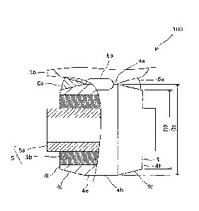
[0004] The strength at the bonding portion of the mounting member can be
also enhanced such that the reinforcement welding is performed at an end
surface side of the mounting member at the bonding portion. However, in the
above-described shock absorber, the outer peripheral surface of the mounting
member has an equal cylindrical shape in a full width. Thus, a space between
the outer peripheral surface of the mounting member and the capping member is
small to make the welding difficult.
[0005] An object of the present invention is to easily perform
reinforcement
welding at an end surface side of a mounting member at a bonding portion of
the
mounting member.
84020269
- 2 -
[0006] According to one aspect of the present invention, a shock absorber
includes a cylindrically-shaped mounting member having an outer
peripheral surface bonded at one end or both ends, the mounting member
having an outer diameter at an end surface side smaller than an outer
diameter at a center portion, and a reinforcement welding performed at the
end surface side of the mounting member at a bonding portion of the
mounting member.
[0006a] According to one aspect of the present invention, there is
provided a shock absorber, comprising: a cylindrically-shaped mounting
member having an outer peripheral surface bonded at one end or both ends,
the mounting member having an outer diameter at an end surface side
smaller than an outer diameter at a center portion; and a reinforcement
welding performed at the end surface side of the mounting member at a
bonding portion of the mounting member, wherein the mounting member is
bonded by projection welding, and the reinforcement welding is performed by
arc welding.
[0006b] According to one aspect of the present invention, there is
provided a shock absorber comprising: a cylindrically-shaped mounting
member having an outer peripheral surface bonded at one end or both ends,
the mounting member having an outer diameter at an end surface side
smaller than an outer diameter at a center portion; a reinforcement welding
performed at the end surface side of the mounting member at a bonding
portion of the mounting member; an outer case in which an operating fluid is
charged; and a piston rod that extends from one end of the outer case,
wherein the mounting member is a mounting eye configured to receive a
bush press-fitted therein, the outer peripheral surface the mounting eye is
bonded on the outer case at the center portion, the mounting eye further
includes end surfaces opposing each other in an axial direction of the
mounting eye, the end surfaces connected by the outer peripheral surface of
Date Recue/Date Received 2023-01-13
84020269
- 2a -
the mounting eye, and at least one bead of the reinforcement welding welds
the mounting eye to the outer case, and has a width decreasing along the
axial direction of the mounting eye from the end surfaces of the mounting
eye toward the center portion of the mounting eye.
BRIEF DESCRIPTION OF DRAWINGS
[0007]
FIG. 1 is a partial cross-sectional view of a shock absorber
according to an embodiment of the present invention.
FIG. 2 is an enlarged view around a mounting eye.
FIG. 3 is a drawing of the mounting eye viewed from a bonding portion
side, and illustrates a state where reinforcement welding is perfolined at
four
places.
FIG. 4 is a drawing of the mounting eye viewed from the bonding
portion side, and illustrates a state where the reinforcement welding is
performed at a whole circumference.
FIG. 5 is a drawing of a mounting eye according to a modification
viewed from a bonding portion side, and illustrates a state where the
reinforcement welding is performed at four places.
FIG. 6 is a partial cross-sectional view of a shock absorber according to
the modification of the present invention.
DESCRIPTION OF EMBODIMENTS
[0008] The following describes a shock absorber 100 according to an
embodiment of the present invention with reference to the attached
drawings.
[0009] The shock absorber 100 is interposed between, for example, a
vehicle
Date Recue/Date Received 2023-01-13
CA 02970862 2017-06-14
- 3 -
body and an axle shaft of an automobile (not illustrated). The shock absorber
100 is a device that generates a damping force to reduce a vibration of the
vehicle
body.
[0010] As illustrated in FIG. 1, the shock absorber 100 includes an outer
case
1, which is charged with a hydraulic oil as an operating fluid, a piston rod
2,
which extends from one end of the outer case 1, an outer cover 3, which is
secured to a distal end side of the piston rod 2 at one end, a mounting eye 4,
which is a mounting member bonded on the outer case 1, and a bush 5, which is
press-fitted in the mounting eye 4.
[0011] The outer case 1 includes a cylindrically-shaped tube la and a
capping member 1 b, which obstructs an end portion opposite to the piston rod
2,
of the tube la. The capping member lb is bonded on the tube la, for example,
by seam welding or projection welding. It should be noted that the outer case
1
may be formed such that the end portion of the tube la is obstructed by
closing
work, without including the capping member lb.
[0012] In the outer case 1, the hydraulic oil is charged, and compressed
gas is
also charged, for example, for preventing cavitation of the hydraulic oil. It
should be noted that other liquid such as water may be used as the operating
fluid.
[0013] The shock absorber 100 may be a mono-tube type, or may be a
twin-tube type. In the case where the shock absorber 100 is the mono-tube
type, the tube la is a cylinder. In the case where the shock absorber 100 is a
twin-tube type, the tube la is an outer tube.
[0014] The piston rod 2 is inserted into the outer case 1 so as to freely
moves
into and out of the outer case 1. At an end portion of the piston rod 2 on a
side
extending from the outer case 1, an external thread 2a for mounting the shock
CA 02970862 2017-06-14
- 4 -
absorber 100 on the vehicle body side is formed.
[0015] The outer cover 3 is secured to the distal end side of the piston
rod 2,
for example, by welding. Specifically, the outer cover 3 includes a bottom
portion 3a, which is secured to the piston rod 2, and a pipe portion 3b, which
is
formed from the bottom portion 3a toward a side of the outer case 1.
[0016] In this embodiment, at the outer cover 3, the bottom portion 3a and
the pipe portion 3b are integrally shaped. A structure of the outer cover 3
may
be, for example, a structure where a tubular member as the pipe portion 3b is
secured to a disk-shaped member as the bottom portion 3a, for example, by
welding or press-fitting.
[0017] The mounting eye 4 has a cylindrical shape, and has an outer
peripheral surface 4e bonded on the outer case 1, which is a bonded member,
for
example, by the projection welding. Specifically, the mounting eye 4 is bonded
on the capping member lb. Reinforcement weldings 6a and 6b are performed
at a bonding portion 4a of the mounting eye 4 to dispose a reinforcement
welding
portion. This will be described later.
[0018] It should be noted that, when the outer case 1 is formed by the
above-described closing work, the mounting eye 4 is directly bonded on a
worked
portion of the tube la.
[0019] The bush 5 includes an inner pipe 5a, into which a bolt (not
illustrated) for mounting the shock absorber 100 on a side of the axle shaft
is
inserted, and a rubber portion 5b, which is adhered to the inner pipe 5a by
vulcanization. It should be noted that, for example, a ball-joint bush may be
used as the bush.
[0020] Subsequently, the reinforcement welding 6a and 6b performed at the
bonding portion 4a of the mounting eye 4 will be described.
CA 02970862 2017-06-14
- 5 -
[0021] The reinforcement welding portion is disposed at the bonding portion
4a of the mounting eye 4. Specifically, as illustrated in FIG. 1 and FIG. 2,
at the
bonding portion 4a of the mounting eye 4, the reinforcement welding 6a is
performed from an axial direction side of the mounting eye 4, that is, an end
surface 4f side of the mounting eye 4, and the reinforcement welding 6b is
performed from a side perpendicular to the axial direction of the mounting eye
4,
that is, a side of the outer peripheral surface 4e of the mounting eye 4. The
reinforcement weldings 6a and 6b are performed, for example, by arc welding.
[0022] In this embodiment, as illustrated in FIG. 3, the reinforcement
welding
6a is performed at both end surfaces 4f sides of the mounting eye 4 at the
bonding portion 4a, and the reinforcement welding 6b is performed at both
outer
peripheral surfaces 4e sides of the mounting eye 4 at the bonding portion 4a.
Thus, in the shock absorber 100, the reinforcement weldings 6a and 6b are
performed at four places: both end surfaces 4f sides and both outer peripheral
surfaces 4e sides of the mounting eye 4 at the bonding portion 4a to enhance a
strength of the bonding portion 4a.
[0023] It should be noted that the reinforcement welding 6a may be
performed only at any one of the end surfaces 4f sides, depending on the
strength required for the bonding portion 4a of the mounting eye 4. The same
applies to the reinforcement welding 6b. Only any of the reinforcement
weldings 6a and 6b may be performed.
[0024] Now, the reinforcement welding 6b can be easily performed such that
a space between the outer peripheral surface 4e of the mounting eye 4 and the
capping member lb is large. Meanwhile, for the reinforcement welding 6a, for
example, when an outer peripheral surface of a mounting eye has an equal
cylindrical shape in a full width, a space between the outer peripheral
surface of
CA 02970862 2017-06-1.4
- 6 -
the mounting eye and the capping member lb is small, thus making the welding
difficult.
[0025] In contrast, in this embodiment, as illustrated in FIG. 2, the
mounting
eye 4 is formed such that an outer diameter D2 at the end surface 4f side is
smaller than an outer diameter D1 of a center portion 4b. Specifically, the
mounting eye 4 includes tapered portions 4c whose outer diameters decrease
from the center portion 4b sides toward the end surfaces 4f sides, at both end
portions.
[0026] This widens a space at the end surface 4f side of the mounting eye 4
at
the bonding portion 4a. Thus, the reinforcement welding 6a can be easily
performed. A space where a bead of the reinforcement welding 6a is fitted can
be ensured. Thus, this can prevent the bead from protruding to an inner
peripheral surface of the mounting eye 4.
[0027] As illustrated in FIG. 3, the tapered portion 4c of the mounting eye
4
has a starting point 4d at the bonding portion 4a side. Such that the starting
point 4d is disposed at the end surface 4f side with respect to the bonding
portion 4a, the tapered portion 4c and the bonding portion 4a do not overlap
one
another.
[0028] That is, in this embodiment, the mounting eye 4 is bonded on the
outer case 1 using an equal cylindrical-shaped part at the outer peripheral
surface 4e. Accordingly, a bond of the mounting eye 4 can be stably performed.
[0029] In the above-described embodiment, the reinforcement weldings 6a
and 6b are performed at the four places: both end surfaces 4f sides and both
outer peripheral surfaces 4e sides of the mounting eye 4 at the bonding
portion
4a. However, as illustrated in FIG. 4, a reinforcement welding 6c may be
performed at a whole circumference of the bonding portion 4a.
CA 02970862 2017-06-1.4
- 7 -
[0030] A shape of the mounting eye, for example, like a shape of a mounting
eye 7 illustrated in FIG. 5, may be a shape that disposes small-diameter
portions
7c whose outer diameters are smaller than an outer diameter of a center
portion
7b, at both end portions.
[0031] This, similarly to the case where the mounting eye 4 is bonded on
the
outer case 1, widens a space at an end surface 7f side of the mounting eye 7
at a
bonding portion 7a. Thus, the reinforcement welding 6a can be easily
performed. A space where the bead of the reinforcement welding 6a is fitted
can
be ensured. Thus, this can prevent the bead from protruding to an inner
peripheral surface of the mounting eye 7.
[0032] The small-diameter portion 7c of the mounting eye 7 has a starting
point 7d at the bonding portion 7a side. Such that the starting point 7d is
disposed at the end surface 7f side with respect to the bonding portion 7a,
the
small-diameter portion 7c and the bonding portion 7a do not overlap one
another.
[0033] That is, the mounting eye 7 is bonded on the outer case 1 using an
equal cylindrical-shaped part at an outer peripheral surface 7e. Accordingly,
a
bond of the mounting eye 7 can be stably performed.
[0034] In the above-described embodiment, the mounting eye 4 is disposed at
the end portion of the outer case 1. However, like a shock absorber 200
illustrated in FIG. 6, the mounting eye 4 may be disposed at an end portion of
the
piston rod 2. The mounting eyes 4 each may be disposed at both ends of the
shock absorber 100, that is, both of the end portion of the outer case 1 and
the
end portion of the piston rod 2.
[0035] The following describes the configuration, the action, and the
effect
according to the embodiment of the present invention as a whole.
CA 02970862 2017-06-14
- 8 -
[0036] In the shock absorber 100, at one end or both ends, the
cylindrically-shaped mounting eyes 4 and 7 whose outer diameters at the end
surfaces 4f and 7f sides are smaller than the outer diameters of the center
portions 4b and 7b are disposed such that the outer peripheral surfaces 4e and
7e are bonded, and the reinforcement weldings 6a and 6c are performed at the
end surfaces 4f and 7f sides of the mounting eyes 4 and 7 at the bonding
portions 4a and 7a of the mounting eyes 4 and 7.
[0037] The mounting eye 4 includes the tapered portions 4c whose outer
diameters decrease from the center portion 4b side toward the end surfaces 4f
sides, at both end portions.
[0038] The mounting eye 7 includes the small-diameter portions 7c whose
outer diameters are smaller than the outer diameter of the center portion 7b,
at
both end portions.
[0039] In these configurations, since the outer diameters at the end
surfaces
4f and 7f sides of the mounting eyes 4 and 7 are smaller than the outer
diameters
of the center portions 4b and 7b, the spaces at the end surfaces 4f and 7f
sides of
the mounting eyes 4 and 7 at the bonding portions 4a and 7a are widened.
Accordingly, the reinforcement weldings 6a and 6c can be easily performed at
the
end surfaces 4f and 7f sides of the mounting eyes 4 and 7 at the bonding
portions 4a and 7a. The spaces where the beads of the reinforcement weldings
6a and 6c are fitted can be ensured. Thus, this can prevent the beads from
protruding to the inner peripheral surfaces of the mounting eyes 4 and 7.
[0040] The starting point 4d at the bonding portion 4a side at the tapered
portion 4c of the mounting eye 4 is disposed at the end surface 4f side with
respect to the bonding portion 4a.
[0041] The starting point 7d at the bonding portion 7a side at the
CA 02970862 2017-06-14
- 9 -
small-diameter portion 7c of the mounting eye 7 is disposed at the end surface
7f
side with respect to the bonding portion 7a.
[0042] In these configurations, the mounting eyes 4 and 7 are bonded on the
shock absorber 100 using the equal cylindrical-shaped parts at the outer
peripheral surfaces 4e and 7e. Accordingly, the bonds of the mounting eyes 4
and 7 can be stably performed.
[0043] The reinforcement weldings 6a and 6b are performed at the four
places: both end surfaces 4f and 7f sides and both outer peripheral surfaces
4e
and 7e sides of the mounting eyes 4 and 7 at the bonding portions 4a and 7a.
[0044] In this configuration, the reinforcement weldings 6a and 6b are
performed at the four places of the bonding portions 4a and 7a to enhance the
strengths of the bonding portions 4a and 7a.
[0045] The reinforcement welding 6c is performed at the whole
circumferences of the bonding portions 4a and 7a.
[0046] In this configuration, the reinforcement welding 6c is performed at
the
whole circumferences of the bonding portions 4a and 7a to enhance the
strengths of the bonding portions 4a and 7a.
[0047] Embodiments of the present invention were described above, but the
above embodiments are merely examples of applications of the present
invention,
and the technical scope of the present invention is not limited to the
specific
constitutions of the above embodiments.
[0048] For example, in the above-described embodiment, the mounting eye 4
includes the tapered portions 4c, and the mounting eye 7 includes the
small-diameter portions 7c. However, the shape of the mounting eye may be a
shape that disposes a tapered portion at one end portion and disposes a
small-diameter portion at the other end portion.
84020269
- 10 -
[0049]
The shape of the end portion of the mounting eye, for example, may be
a shape that changes to the small-diameter portion in its course of the
tapered
portion from the center portion side toward the end surface side, or may be a
shape that changes to the tapered portion in its course of the small-diameter
portion.
Date Recue/Date Received 2022-02-25