Note : Les descriptions sont présentées dans la langue officielle dans laquelle elles ont été soumises.
CA 02972439 2017-06-27
WO 2016/109707
PCT/US2015/068122
SAFETY INTRAVENOUS CATHETER WITH FRICTION-BASED RETENTION AND
DISABLING FEATURE
Field of the Invention
[0001] The present invention relates to intravenous catheters, and more
particularly, to an
intravenous catheter with friction-based retention between a catheter hub and
a needle shield.
Background of the invention
[0002] Catheters, particularly intravenous (IV) catheters, are used for
infusing fluid (such
as normal saline solution, various medicaments, and total parenteral
nutrition) into a patient,
withdrawing blood from a patient, or monitoring various parameters of the
patient's vascular
system. Peripheral IV catheters tend to be relatively short, and typically are
on the order of
about two inches or less in length. The most common type of IV catheter is an
over-the-
needle peripheral IV catheter. As its name implies, an over-the-needle
catheter is mounted
over a hollow introducer needle having a sharp distal tip. At least the distal
portion of the
catheter tightly engages the outer surface of the needle to prevent peelback
of the catheter and
thus facilitates insertion of the catheter into the blood vessel. The catheter
and the introducer
needle are assembled so that the sharp distal tip of the introducer needle
extends beyond the
distal tip of the catheter with the bevel of the needle facing up and away
from the patient's
skin.
[0003] In operation, the catheter and introducer needle assembly is
inserted at a shallow
angle through the patient's skin into a blood vessel. There are many
techniques for inserting
such a catheter and introducer needle assembly into a patient. In one
insertion technique, the
introducer needle and catheter are inserted completely into the blood vessel
together. In
another technique, the introducer needle is partially withdrawn into the
catheter after the
initial insertion into the blood vessel. The catheter is then threaded over
the needle and
inserted completely into the blood vessel.
[0004] To verify proper placement of the catheter in the blood vessel, the
clinician
confirms that there is flashback of blood in a flashback chamber. The
flashback chamber is
typically formed as part of the introducer needle hub. Once proper placement
of the catheter
into the blood vessel is confirmed, the clinician applies pressure to the
blood vessel by
pressing down on the patient's skin over the blood vessel distal of the
introducer needle and
the catheter. This finger pressure occludes or at least minimizes further
blood flow through
the introducer needle and the catheter. The clinician then withdraws the
introducer needle,
leaving the catheter in place, and attaches an appropriate device to the
catheter. Such a device
can include a fluid delivery device, a PRN device (pro re nata ¨ i.e., "as the
circumstances
may require"), a deadender cap, or a blood pressure monitoring probe. Once the
introducer
needle is withdrawn from the catheter, the introducer needle is a blood
contaminated sharp
and must be properly handled and disposed of.
[0005] In recent years, there has been great concern over the contamination
of clinicians
with a patient's blood and recognition that blood contaminated sharps must be
properly
handled and disposed of to avoid an accidental needle stick. This concern has
arisen because
of diseases such as HIV and hepatitis, which can be transmitted by the
exchange of body
fluids from an infected person to another person. Contact with the body fluid
of an infected
person must be avoided. If an introducer needle has been used to place a
catheter in a blood
vessel of an infected person, the introducer needle, via its sharp distal tip,
is a vehicle for the
transmission of the disease. Although clinicians know of the need to properly
handle blood
contaminated sharps, unfortunately in certain medical environments, such as
emergency
situations or because of inattention or neglect, needlesticks with a
contaminated introducer
needle can still occur.
[0006] Because of the problem of accidental needlesticks by blood
contaminated sharps,
various types of needle shields have been developed. Generally, such needle
shields work for
their intended purpose but could be improved. For example, some needle shields
are bulky,
difficult to use, require special features or techniques to be operative, or
may leave the sharp
distal tip exposed after use until the clinician manually activates the needle
shielding
mechanism.
[0007] Although U.S. Patent No. 6,749,588, which is assigned to the same
assignee as
the present application, sets forth many solutions to such problems, other
solutions are also
desirable. Some solutions employ a projection engaging a recess or undercut to
provide an
interlock to keep a needle shield retained with a catheter hub, but these
solutions can require
detailed or intricate molding or manufacturing.
Summary of Embodiments
[0008] It is an aspect of the present invention to provide an intravenous
catheter with
friction-based retention between a catheter hub and a needle shield.
2
Date Recue/Date Received 2020-10-19
CA 02972439 2017-06-27
WO 2016/109707
PCT1US2015/068122
[0009] The foregoing and/or other aspects of the present invention are
achieved by
providing a catheter and introducer needle assembly, including a flexible
catheter having a
proximal end and a distal end, and a catheter hub in fluid communication with
the proximal
end of the catheter and having a distal end connected to the proximal end of
the catheter, the
catheter hub having an uninterrupted outer surface portion and a Luer-
connecting feature. The
assembly also includes an introducer needle disposed in the catheter and
having a proximal
end and a distal end, and an axis extending from the proximal end to the
distal end; and a
needle shield having a proximal portion and a distal portion. The assembly
additionally
includes a resilient clip adapted to flex between a first position and a
second position in a
plane perpendicular to the axis of the introducer needle, the resilient clip
having a
cantilevered arm with a pawl; and a disabling feature extending radially
outward from a
proximal portion of the catheter hub and being axially aligned with and spaced
apart from the
pawl when the resilient clip is in the first position. In the first position
of the resilient clip, the
cantilevered arm of the resilient clip is flexed so that the pawl frictionally
contacts the
uninterrupted outer surface portion of the catheter hub and thereby
frictionally retains the
needle shield with the catheter hub, and in the second position of the
resilient clip, the pawl
no longer frictionally contacts the uninterrupted outer surface portion,
thereby permitting
displacement of the needle shield relative to the catheter hub.
[0010] Preferably when the distal end of the introducer needle extends
distally past the
resilient clip, the resilient clip is held to one side of the introducer
needle in a biased position.
Upon the sharp distal end of the introducer needle being proximally withdrawn
past the
flexible clip, the flexible clip flexes to an unbiased or less biased position
in which it no
longer frictionally retains the needle shield with the catheter hub.
[0011] The resilient clip may comprise an angled clip, at least a portion
of which is
movably disposed within the needle shield. The angled clip may have an angled
portion with
the cantilevered arm extending therefrom. Alternatively, or in addition, the
resilient clip may
comprise an angled portion having a needle blocker extending therefrom;
wherein when the
flexible clip flexes to the unbiased or less biased position, the needle
blocker is disposed to
prevent distal displacement of the distal end of introducer needle distal
outside of the needle
shield.
[0012] In certain embodiments, the catheter hub includes a proximal port
adapted for
fluid communication with the catheter and connection with a Luer connector.
The catheter
3
CA 02972439 2017-06-27
WO 2016/109707
PCT1US2015/068122
hub may further comprise a secondary side port adapted for fluid communication
with the
catheter when the proximal port is in use.
[0013] The assembly may further comprise a needle hub disposed at the
proximal end of
the introducer needle. A flexible tether may be located connecting the needle
shield and the
needle hub.
[0014] The assembly may further comprise a flexible cantilevered fin
extending radially
from the needle shield toward a central axis of the needle shield. The fm is
preferably
disposed between the introducer needle and the resilient clip.
[0015] In certain embodiments, the assembly further comprises a septum and
an actuator
disposed within the catheter hub; wherein the septum is pierceable by actuator
displacement;
and the resilient clip is disposed proximal to the septum.
[0016] In preferred embodiments, a normal force applied by the pawl on the
uninterrupted outer surface portion of the catheter hub is in the range of 0.4
to 1.4 Newtons.
Additionally, or separately, a coefficient of friction between the pawl and
the uninterrupted
outer surface portion of the catheter hub is in the range of 0.23 to 0.4.
[0017] The foregoing and/or other aspects of the present invention are also
achieved by
providing a catheter and introducer needle assembly, including a catheter hub
having a first
fluid path, an uninterrupted outer surface portion, and a disabling feature
extending radially
outward from a proximal portion of the catheter hub; a catheter communicating
with the first
fluid path; and an introducer needle assembly. The introducer needle assembly
includes an
introducer needle, a needle hub fixedly disposed at a proximal end of the
introducer needle; a
needle shield selectively disposed at the catheter hub and connected with the
needle hub; and
a resilient clip. The introducer needle is disposed through the needle shield,
the catheter hub,
and the catheter. The resilient clip is movably disposed within the needle
shield and has a
cantilevered arm extending therefrom with a pawl at the free end of the
cantilevered arm. The
cantilevered arm is flexed so that the pawl frictionally contacts the
uninterrupted outer
surface portion and frictionally retains the needle shield with the catheter
hub. The disabling
feature is axially aligned with and spaced apart from the pawl.
[0018] The hub may further comprise a Luer-connecting feature.
[0019] Preferably the introducer needle holds the resilient clip in a first
compressed
position until a sharpened distal end of the introducer needle proximally
passes the resilient
clip; and subsequent to the distal end of the introducer needle proximally
passing the resilient
4
CA 02972439 2017-06-27
WO 2016/109707
PCT1US2015/068122
clip, the resilient clip expands laterally to an unbiased or less biased
position in which the
pawl no longer frictionally contacts the uninterrupted outer surface portion
and the resilient
clip no longer frictionally retains the needle shield with the catheter hub.
[0020] The resilient clip may comprise an angled clip having an angled
portion with the
cantilevered arm extending therefrom.
[0021] In certain embodiments, the catheter hub includes a proximal port
adapted for
fluid communication with the catheter and connection with a Lucr connector.
Preferably also
the catheter hub comprises a secondary side port adapted for fluid
communication with the
catheter when the proximal port is in use.
[0022] Preferably a flexible tether connects the needle shield and the
needle hub.
[0023] The assembly may further comprise a flexible cantilevered fin
extending radially
from the needle shield toward a central axis of the needle shield. The fin is
preferably
disposed between the introducer needle and the resilient clip.
[0024] In certain embodiments the assembly further comprises a septum and
an actuator
disposed within the catheter hub; wherein the septum is pierceable by actuator
displacement.
In such embodiments, the resilient clip may be disposed proximal to the
septum.
[0025] Preferably a normal force applied by the pawl on the uninterrupted
outer surface
portion is in the range of 0.4 to 1.4 Newtons. Alternatively, or in addition,
a coefficient of
friction between the pawl and the uninterrupted outer surface portion is in
the range of 0.25 to
0.4.
[0026] The foregoing and/or other aspects of the present invention are also
achieved by
providing a catheter and introducer needle assembly, including a flexible
catheter having a
proximal end and a distal end, and a catheter hub with a distal end connected
to the proximal
end of the catheter. The catheter hub includes an uninterrupted outer surface
portion, at least
one wing to aid in securing the catheter hub to a patient, a proximal port in
fluid
communication with the proximal end of the catheter, a secondary side port
with a valve
disposed therein for selective fluid communication with the proximal end of
the catheter, a
Lucr-connecting feature. and a disabling feature extending radially outward
from a proximal
portion of the catheter hub. The assembly also includes an introducer needle
having a
proximal end, a sharpened distal end, and an axis extending from the proximal
end to the
distal end: a needle hub fixedly disposed at the proximal end of the
introducer needle; a
needle shield having a proximal portion and a distal portion, and also having
a flexible
CA 02972439 2017-06-27
WO 2016/109707
PCT1US2015/068122
cantilevered fm extending toward a central axis of the needle shield; an
expandable tether
connecting the proximal portion of the needle shield with a distal portion of
the needle hub;
and a resilient clip adapted to flex between a first position and a second
position in a plane
perpendicular to the axis on the introducer needle. The resilient clip
includes an anchoring
portion anchoring the resilient clip in the needle shield, an angled portion
extending from the
anchoring portion and having a needle blocker extending therefrom, a
cantilevered arm
extending distally from the angled portion, and a pawl disposed at a distal
end of the
cantilevered arm, extending toward the catheter hub.
[0027] In an initial assembly configuration, the introducer needle is
disposed through the
needle shield, the catheter hub. and the catheter so that the sharpened distal
end of the
introducer needle extends beyond the distal end of the catheter; the needle
shield is disposed
at the proximal end of the catheter hub and at least a portion of the needle
shield is disposed
within the needle hub; the tether is in a collapsed state; the resilient clip
is flexed into the first
position by the introducer needle, with the fin of the needle shield being
disposed between the
introducer needle and the angled portion of the resilient clip; the needle
blocker of the
resilient clip is not disposed across a pathway of the introducer needle; the
pawl is axially
aligned with and spaced apart from the disabling feature; and the cantilevered
arm of the
resilient clip is flexed so that the pawl frictionally contacts the
uninterrupted outer surface
portion of the catheter hub at a distance from the disabling feature and
frictionally retains the
needle shield with the catheter hub. In a deployed assembly configuration
subsequent to the
withdrawal of the sharpened distal end of the introducer needle proximally
past the resilient
clip, the tether is extended and the resilient clip is disposed in the second
position, in which
the needle blocker is disposed across a pathway of the introducer needle and
the pawl no
longer frictionally contacts the uninterrupted outer surface portion, thereby
permitting
displacement of the needle shield relative to the catheter hub and preventing
displacement of
the sharpened distal tip of the introducer needle distally past the resilient
clip.
[0028] It will be understood that each of the preferred or optional
features of the various
embodiments described above may be combined with other preferred or optional
features.
Additionally, features described in combination with one particular embodiment
may also be
combined with one of the other embodiments.
[0029] Additional and/or other aspects and advantages of the present
invention will be set
forth in the description that follows, or will be apparent from the
description, or may be
learned by practice of the invention.
6
CA 02972439 2017-06-27
WO 2016/109707
PCT1US2015/068122
Brief Description of the Drawings
[0030] The above and/or other aspects and advantages of embodiments of the
invention
will be more readily appreciated from the following detailed description,
taken in conjunction
with the accompanying drawings, in which:
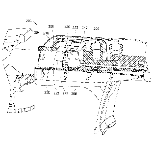
Fig. 1 is a top perspective view of a safety intravenous catheter assembly in
accordance with an embodiment;
Fig. 2 is a bottom perspective partial view, partially in cross-section, of
the
catheter assembly of Fig. 1;
Fig. 3 is a bottom perspective view of a resilient clip of the catheter
assembly of
Fig. 1 in a first biased position;
Fig. 4 is a bottom perspective view of the resilient clip of Fig. 3 in a
second,
unbiased or less biased position;
Fig. 5 is an enlarged bottom perspective view, partially in cross-section. of
the
catheter assembly of Fig. 1;
Fig. 6 is an enlarged partial rear perspective cross-sectional view of the
catheter
assembly of Fig. 1;
Fig. 7 is an enlarged bottom rear perspective view, partially in cross-
section, of the
catheter assembly of Fig. 1 after the resilient clip has been activated;
Fig. 8 is another enlarged bottom rear perspective view, partially in cross-
section,
of the catheter assembly of Fig. 1 after the resilient clip has been
activated;
Fig. 9 is a bottom perspective view of the catheter assembly of Fig. 1 after a
needle shield has been removed from a catheter hub;
Fig. 10 is an enlarged bottom perspective view, partially in cross-section, of
a
catheter assembly in accordance with another embodiment;
Fig. Ills an enlarged bottom perspective view, partially in cross-section, of
a
catheter assembly in accordance with yet another embodiment; and
Fig. 12 is an enlarged bottom perspective view, partially in cross-section, of
a
catheter assembly in accordance with yet another embodiment.
Detailed Description of Embodiments
[0031] Reference will now be made in detail to embodiments of the present
invention,
which are illustrated in the accompanying drawings, wherein like reference
numerals refer to
like elements throughout. The embodiments described herein exemplify, but do
not limit, the
present invention by referring to the drawings.
7
[0032] It will be understood by one skilled in the art that this disclosure
is not limited in
its application to the details of construction and the arrangement of
components in the
following description or illustrated in the drawings. The embodiments herein
are capable of
other embodiments, and capable of being practiced or carried out in various
ways. Also, it
will be understood that the phraseology and terminology used herein is for the
purpose of
description and should not be regarded as limiting. The use of "including,"
"comprising," or
"having" and variations thereof encompasses the items listed thereafter and
equivalents
thereof as well as additional items. Unless limited otherwise, the terms
"connected,"
"coupled," and "mounted," and variations thereof are used broadly and
encompass direct and
indirect connections, couplings, and mountings. In addition, the terms
"connected" and
"coupled" and variations thereof are not restricted to physical or mechanical
connections or
couplings. Further, terms such as up, down, bottom, and top are relative, and
are employed to
aid illustration, but are not limiting.
[0033] Fig. 1 is a top perspective view of a safety intravenous catheter
assembly 100
embodiment in a ready-to-use state, and Fig. 2 is a bottom perspective view,
partially in
cross-section, of the catheter assembly 100. The catheter assembly 100
includes a flexible
plastic catheter 102 secured with a catheter hub 104. The catheter 102 and the
catheter hub
104 form a first fluid pathway extending along a longitudinal axis of the
catheter 102 and
proximally terminating at a proximal port 103 (best shown in Fig. 9) adapted
for connection
with, for example, a Luer fitting, using Luer lugs or thread segments 128.
[0034] Additionally, according to one embodiment, the catheter hub 104 may
include
stabilization wings 107, which facilitate skin attachment after the catheter
is inserted, for
example, by securing the wings 107 to the skin with tape. The catheter hub 104
also may
include a secondary side port 105 that forms a second fluid pathway in
communication with
the first fluid pathway. As described in U.S. Patent No. 4,231,367, the
secondary side port
105 preferably includes a barrier, such as an internal tubular valve. The
secondary side port
105 can be used, for example, to introduce additional fluid or medicament into
a patient
when the proximal port 103 is already in use. In this embodiment, the proximal
end of the
catheter hub 104 is substantially cylindrical. According to another
embodiment, the catheter
hub 104 does not include stabilization wings or a secondary side port.
[0035] Suitable materials for the flexible catheter 102 include, but are
not limited to,
thermoplastic resins such as fluorinated ethylene propylene (FEP),
polytetrafluoroethylene
8
Date Recue/Date Received 2020-10-19
CA 02972439 2017-06-27
WO 2016/109707
PCT1US2015/068122
(PTFE), polyurethane and the like. Preferably, the catheter 102 is formed from
a
thermoplastic hydrophilic polyurethane that softens with exposure to
physiological conditions
present in the patient's body. Suitable materials for the catheter hub 104
include, but are not
limited to, thermoplastic polymeric resins such as polycarbonate, polystyrene,
polypropylene,
and the like.
[0036] The catheter assembly 100 also includes a hollow introducer needle
106 having a
sharp distal tip defined by an upwardly facing bevel and a proximal end
fixedly connected to
a handle portion or needle hub 108 and disposed within the catheter 102. The
introducer
needle 106 is preferably formed from stainless steel and has a longitudinal
axis generally
parallel to the longitudinal axis of catheter and introducer needle assembly
100. The handle
portion 108 may be formed from the same types of materials used to form
catheter hub 104,
but other materials could also be used to form the handle portion 108.
[0037] The catheter assembly 100 additionally includes a needle shield 110
and a resilient
clip 112. According to one embodiment, the resilient clip 112 may be a V-
shaped or W-
shaped clip 112. Preferably, the resilient clip 112 is formed from stainless
steel having a
memory characteristic. It will be understood by one skilled in the art,
however, that other
flexible, strong, resilient materials could also be used to form the resilient
clip 112, such as
nitinol, co-polyesters, polypropylene, or other ductile plastics. The needle
shield 110 may be
formed from the same types of materials used to form catheter hub 104, but
other materials
could also be used to form the needle shield 110. The needle shield 110 has
distal and
proximal orifices 111 and 113 (best shown, respectively, in Figs. 6 and 7)
through which the
introducer needle 106 is disposed.
[0038] Initially, in the illustrated ready-to-use state, the needle shield
110 is located
within the handle portion 108, and a distal end 131 of the needle shield 110
is located within
the catheter hub 104 to help center the needle shield 110 with respect to the
catheter hub 104.
This distal end 131 also provides stability for the introducer needle 106 and
blood retention
for the catheter hub 104 as the assembly 100 is being inserted into a patient.
[0039] According to one embodiment, a flexible tether 134 connects the
handle portion
108 and the needle shield 110. In all but Fig. 9, however, the tether 134 is
omitted from the
drawings for clarity. As subsequently discussed in greater detail, one skilled
in the art will
appreciate that other mechanisms for connecting the handle portion 108 and the
needle shield
110 can be employed without departing from the scope of the present invention,
for example,
9
CA 02972439 2017-06-27
WO 2016/109707
PCT1US2015/068122
a bump on the introducer needle 106 and a corresponding catch feature in the
resilient clip
112, or a washer type feature in the needle shield 110. As best shown in Fig.
7, slots 130 in
the needle shield 110 cooperate with the Luer lugs 128 of the catheter hub 104
to prevent
rotation of the needle shield 110 relative to the catheter hub 104.
[0040] As subsequently described in greater detail regarding the operation
of the catheter
assembly 100, Figs. 3 and 4 respectively illustrate the resilient clip 112 in
a first, biased
position, and in a second, unbiased or less biased position. According to one
embodiment, in
the second position, the resilient clip is not biased. As shown in Figs. 3 and
4, the resilient
clip 112 includes an anchoring portion 114 for anchoring the resilient clip
112 in the needle
shield 110 so that when the resilient clip moves, it moves in a direction
substantially
perpendicular to the longitudinal direction of the introducer needle 106 and
catheter 102.
[0041] The resilient clip 112 also includes an angled portion 116 with a
needle blocker or
transverse barrier 118 extending substantially perpendicular to the angled
portion 116.
According to one embodiment, the angled portion 116 is V-shaped. According to
the
embodiment shown, the needle blocker 118 extends from a distal portion of the
angled
portion 116. According to another embodiment, the needle blocker 118 extends
from a
proximal portion of the angled portion 116. As shown in Figs. 3 and 4, the
needle blocker
extends from only one side of the V-shaped angled portion (i.e.. one arm of
the V-shape).
According to yet another embodiment, a needle blocker 118 extends from each
side of the
angled portion 118 toward the middle of the angled portion 118. A cantilevered
arm 120 also
extends from the angled portion 116, and a finger or pawl 122 extends radially
inward from
the free, distal end of the cantilevered arm 120. The resilient clip 112 also
includes a
stiffening or reinforcing rib 121 for stiffening the cantilevered arm 120.
Further details of a
similar resilient clip can be found in the aforementioned U.S. Patent No.
6,749,588.
[0042] Referring to Figs. 2, 5, and 6, in the illustrated ready-to-use
state, the needle shield
110 is disposed at the proximal portion of the catheter hub 104. Anchoring
portion 114 is
fixedly disposed within a cavity 124 of the needle shield 110. According to
one embodiment,
the introducer needle 106 directly contacts a side of the angled portion 116
and holds the
resilient clip 112 in the first or biased position.
[0043] The contact between the introducer needle 106 and the angled portion
116 of the
resilient clip 112 generates a normal force at the interface. This normal
force is opposed by
the resulting normal forces between the introducer needle 106 and the distal
and proximal
CA 02972439 2017-06-27
WO 2016/109707
PCT1US2015/068122
orifices of the needle shield 110. In use, when the introducer needle 106 is
proximally
withdrawn, there will be friction forces at these three interfaces (i.e.,
between the introducer
needle 106 and the distal and proximal orifices 111 and 113, and between the
introducer
needle 106 and the angled portion 116), and these reactive frictional forces
are directed in the
proximal direction. These frictional forces are proportional to the normal
forces and the
friction coefficients at the three interfaces. In addition to the direct
contact friction (if any)
between the needle shield 110 and the needle hub 108, and the proximal force
generated by
the tether 134 as the needle hub 108 is moved in the proximal direction, these
frictional
forces act to pull the needle shield 110 in the proximal direction. As
subsequently described
in greater detail, during withdrawal of the introducer needle 106, the
summation of the forces
on the needle shield 110 in the proximal direction is less than the summation
of forces on the
needle shield 110 in the distal direction (primarily generated by the
interaction between the
pawl 122 and an uninterrupted outer surface portion 126 of the catheter hub
104), thereby
keeping the needle shield 110 in contact with the catheter hub 104 until the
resilient clip 112
is activated, to avoid accidental exposure of the sharp distal end of the
introducer needle 106.
[0044] According to another embodiment, as best shown in Fig. 6, a thin,
flexible
cantilevered extension or fin 123 extends radially inward from the needle
shield 110 toward a
central axis of the needle shield 110 to rest against a side of the angled
portion 116 and
intervene between the angled portion 116 and the introducer needle 106. The
coefficient of
friction between metal and metal is higher than the coefficient of friction
between metal and
the material or materials used to form the needle shield 110 and fin 123, for
example,
thermoplastic polymeric resins such as polycarbonate, polystyrene,
polypropylene, and the
like. Thus, in comparison to the introducer needle 106 directly contacting the
angled portion
116 (with a coefficient of friction of about 0.5-0.6), the fin 123 reduces
frictional contact with
introducer needle 106 to a coefficient of friction of about 0.25-0.4. The
introducer needle 106
holds the resilient clip 112 in the first or biased position via the fin 123.
[0045] According to another embodiment, to further reduce the friction
between the fin
123 and the introducer needle 106, a lubricant, such as a silicone lubricant,
is disposed on the
fin 123. One skilled in the art will appreciate that other lubricants can be
employed without
departing from the scope of the present invention. Additionally, as shown in
Fig. 6, the
introducer needle extends through the orifice 111 in a distal portion 125 of
the needle shield
110, which contacts and guides the introducer needle 106. An orifice 113 in a
proximal
portion of the needle shield 110 (visible in Fig. 7) also contacts and guides
the introducer
11
CA 02972439 2017-06-27
WO 2016/109707
PCT1US2015/068122
needle 106. According to one embodiment, the lubricant can be employed on the
introducer
needle 106 and/or the needle shield 110 (e.g., at the two orifices 111 and
113) to reduce
friction between the needle shield 110 and the introducer needle 106.
[0046] The cantilevered arm 120 is flexed or bent to cause the pawl 122,
which extends
radially toward the catheter hub 104, to frictionally contact the
uninterrupted outer surface
portion 126 of the catheter hub 104 and thereby frictionally retain the needle
shield 110 with
the catheter hub 104. Additionally, contact between the distal end 131 of the
needle shield
110 and the catheter huh 104, as well as contact between the Luer lugs 128 and
the needle
shield 110, may play a role in frictionally retaining the needle shield 110
with the catheter
hub 104. The sum of these retaining forces is chosen to be greater than the
sum of the
previously described forces (e.g., those resulting from the proximally moving
introducer
needle 106) that tend to separate the needle shield 110 from the catheter hub
104.
[0047] The uninterrupted outer surface portion 126 is continuous, and
substantially
featureless. In other words, on the uninterrupted outer surface portion 126,
no cavities or
recesses or protrusions exist, so that the uninterrupted outer surf= portion
126 is unbroken.
The uninterrupted outer surface portion 126 may be smooth, or may be provided
with a
surface texture to enhance friction. According to one embodiment, the portion
of the catheter
hub 104 in which the uninterrupted outer surface portion 126 is disposed is
substantially
cylindrical.
[0048] In use, the doctor, nurse, other medical professional, or other user
(hereinafter
"use?' for brevity) grasps the catheter assembly 100 and inserts the
introducer needle 106 and
catheter 102 into the patient's vein. After the catheter is placed in the
patient's vein, the user
begins to proximally withdraw the introducer needle using the needle hub 108
while holding
the catheter 102 in position. Thus, the introducer needle 106 is moving
relative to the catheter
hub. Because of the differential between the greater frictional force of the
pawl 122
interacting with the uninterrupted outer surface portion 126 and the sum of
the lesser
frictional force of the introducer needle 106 interacting with the resilient
clip 112 and the
needle shield 110, and the proximal forces in the tether 134, the pawl 122
retains the needle
shield 110 with the catheter hub 104. In short, the frictional force generated
by the contact
between the pawl 122 and the uninterrupted outer surface portion 126 is
greater than the force
required to overcome the drag forces on the introducer needle 106. In other
words, because
the frictional resistance between the pawl 122 and the uninterrupted outer
surface portion 126
is greater than the sum of the frictional resistance between the introducer
needle 106 and the
12
CA 02972439 2017-06-27
WO 2016/109707
PCT1US2015/068122
needle shield 110 and between the introducer needle 106 and the resilient clip
112, and the
proximal force in the tether, the pawl 122 retains the needle shield 110 with
the catheter hub
104 as the user proximally withdraws the introducer needle 106. Put another
way, the
releasable retention force resulting from the interaction between the pawl 122
and the
uninterrupted outer surface portion 126 is only frictional, and this
releasable frictional force
frictionally retains the needle shield 110 with the catheter hub 104 against
forces in the
proximal direction generated as the introducer needle is withdrawn in the
proximal direction.
[0049] As shown in Fig. 7, once the user proximally withdraws the sharp
distal end of the
introducer needle 106 past the proximal edge of the resilient clip 112, the
introducer needle
106 no longer compresses and holds the resilient clip 112 in the first, biased
position. As a
result, the resilient clip 112 activates and expands laterally in a direction
substantially
perpendicular to the longitudinal axis of the introducer needle 106 to the
second, unbiased or
less biased position (best illustrated in Fig. 4), causing the pawl 122 to
move laterally out of
contact with the uninterrupted outer surface portion 126. In addition, as
shown in Fig. 8, the
needle blacker 118 moves into a position across the longitudinal axis of the
introducer needle
106, thereby preventing the user from distally displacing the introducer
needle 106 past the
needle blacker 118, and potentially re-exposing the sharp distal tip of the
introducer needle
106. Thus, once the resilient clip 112 activates, the resilient clip 112 no
longer frictionally
retains the needle shield 110 with the catheter hub 104, and the resilient
clip 112 prevents the
introducer needle from displacing distally past the resilient clip 112.
[0050] As previously noted, the flexible tether 134 connects the needle
shield 110 with
the needle hub 108. As the user proximally displaces the introducer needle
from the ready-to-
use state illustrated in Fig. 1 to the clip-activated state illustrated in
Fig. 7, the tether 134
expands substantially to its full length, preventing further proximal
displacement of the
introducer needle 106 relative to the needle shield 110. The needle blacker
118 prevents the
introducer needle 106 from displacing distally relative to the needle shield
110 because the
sharp distal tip of the introducer needle 106 is safely captured within the
needle shield 110.
[0051] Because the resilient clip no longer frictionally retains the needle
shield 110 with
the catheter hub 104, as the user continues to proximally displace the
introducer needle 106,
the proximal force applied by the fully extended tether overcomes any
remaining friction and
separates the needle shield 110 from the catheter hub 104, as shown in Fig. 9,
thereby
exposing the proximal port 103 for connection with medicament or other fluids.
13
CA 02972439 2017-06-27
WO 2016/109707
PCT1US2015/068122
[0052] In embodiments of the present invention, there is a balance of
forces to provide
the desired operation. For example, the frictional force of the contact
between the pawl 122
and the uninterrupted outer surface portion 126 is chosen to exceed the
remaining forces
acting on the introducer needle 106 and the needle shield 110 during initial
withdrawal of the
introducer needle 106 to frictionally retain the needle shield 110 with the
catheter hub 104.
Thus, the goal is to increase the frictional force of the pawl-catheter hub
interface and to
decrease the frictional forces of the interactions of other device components.
By achieving the
desired balance of forces without resorting to recesses or undercuts on the
catheter hub 104 to
retain the catheter hub 104 with the needle shield 110 prior to activation of
the resilient clip
112, the manufacturing of the assembly 100 can be simplified.
[0053] The frictional force (Fe) of the contact between the pawl 122 and
the uninterrupted
outer surface portion 126 is defined as being equal to IAN, where It is the
coefficient of
friction and N is the "normal force" or the force that is applied normal
(perpendicular) to the
uninterrupted outer surface portion 126. Thus, the frictional force can be
increased by
increasing the normal force applied by the pawl 122, by increasing the
coefficient of friction
of the uninterrupted outer surface portion 126, or both.
[0054] According to the embodiment shown in Figs. 3 and 4, the edge of the
pawl 122
that contacts the uninterrupted outer surface portion 126 is substantially
linear. The shape of
the pawl end, however, can be modified to optimize this contact. Although
contact area is not
a term in the frictional equation, optimizing the contact area can help
provide a better
mechanical interface between the two parts. This can be accomplished by
shaping the pawl
end to match the curvature of the uninterrupted outer surface portion 126.
Different gauge
insertion needles, however will compress the angled portion 116 of the
resilient clip 112 to
different degrees, and therefore, will affect the positioning of the pawl 122.
Accordingly, the
linear shape of the pawl 122 illustrated in Figs. 3 and 4 represents a shape
optimized to
provide the desired normal force in combination with a range of different
gauge introducer
needles.
[0055] The pawl arm edge condition can be also be optimized. For example,
the pawl
edge can be sharpened, which can help by digging or biting into the softer
plastic material of
the catheter hub 104. In addition, the cantilevered arm 120 can be stiffened
using features
such as additional stiffening ribs or gussets that provide a higher normal
force on the
uninterrupted outer surface portion 126 as the cantilevered arm 120 is flexed,
thus increasing
the total frictional force. Further, the height or length of the pawl 122 can
be adjusted to
14
CA 02972439 2017-06-27
WO 2016/109707
PCT1US2015/068122
provide a greater pawl arm bias angle. If the pawl is taller, the cantilevered
arm 120 must
bend further, thereby providing a higher normal force, and thus, a greater
frictional force.
[0056] The diameter of the catheter hub 104 at the uninterrupted outer
surface portion can
be increased to increase the bending of the cantilevered arm 120, thereby
increasing the
normal force and the resulting frictional force. The tip of the pawl 122 can
also be covered
with a material that has a higher coefficient of friction than that provided
by the metal alone,
for example, a rubber compound. In addition, the uninterrupted outer surface
portion 126 can
be formed, treated, or processed (e.g., machined) to provide more surface
roughness, which
can increase the coefficient of friction and the resulting friction force.
Moreover, the
uninterrupted outer surface portion 126 can have a coating or a second
material injected over
the plastic of the catheter hub 104 in a two-shot molding operation. For
example, such a
coating or second material can be a rubber or a soft touch plastic coating.
The coefficient of
friction between rubber and metal can approach one, and thereby more
efficiently translate
the normal force into a higher frictional retaining force.
[0057] The coefficient of friction between metal and plastic can range
between 0.25 and
0.4. The predicted normal force of the pawl 122 on the uninterrupted outer
surface portion
126 is approximately 0.4 Newtons to 1.4 Newtons, with an average around 0.8
Newtons to 1
Newton. In addition to the above-noted factors, other factors are also
included in these
predictions. For example, the initial friction (tip adhesions and catheter
drag force) between
the introducer needle 106 and the catheter 102, flexing of the cantilevered
arm 120 during
operation, other material deformation, the pawl 122 biting into the
uninterrupted outer surface
portion 126, and chatter between the pawl 122 and the uninterrupted outer
surface portion
126, all add together to provide the pawl-catheter hub holding force.
[0058] There are several ways to reduce the frictional forces of the
interactions of other
device components. For example, as previously noted with respect to the fin
123, lubrication
can be placed where device components interact. The coefficient of friction
between plastic
and plastic for static dry conditions can range between 0.3 and 0.4. With
lubrication, this
amount can be almost eliminated. A good candidate for such plastic-plastic
lubrication is
between the needle hub 108 and the needle shield 110.
[0059] In addition, if instead of a tether 134, a washer is used as the
mechanism for
retaining the needle shield 110 with the needle hub 108 (as subsequently
described with
respect to another embodiment), lubrication, washer edge finishing levels, and
the finish of
CA 02972439 2017-06-27
WO 2016/109707
PCT1US2015/068122
the introducer needle 106 can all be optimized to reduce friction. Further,
the resilient clip
112 can be optimized for specific introducer needle gauge sizes. For example,
for smaller
gauge introducer needles 106, the resilient clip 112 is not as compressed as
with larger
introducer needles. Therefore. for smaller gauge introducer needles, the
resilient clip 112 can
be made thinner to provide the proper yielding force. The thinner resilient
clip 112 will
provide less normal force to the introducer needle 106. For larger gauge
introducer needles,
the resilient clip 112 endures greater lateral displacement. The material
thickness and the
hardness of the resilient clip 112 play a role in providing the proper
restoring force, but
consequently the force applied to the needle increases.
[0060] Fig. 10 is an enlarged bottom perspective view, in partial cross-
section, of another
catheter assembly embodiment. For this and other subsequently-described
embodiments, all
reference characters designating corresponding parts of the embodiments are
the same as
those in the embodiment of Figs. 1-9, except that they are in a different
series, for example, in
the 100 series, or the 200 series. The differences of the second embodiment
with respect to
the first embodiment will now be described.
[0061] As discussed, the protection of the user from accidental needle
sticks is a concern.
Thus, a disabling feature 232 in the form of an integral, radially extending
projection is
disposed at the proximal end of the catheter hub 204 in the event that the
user improperly
uses the device in such a way that would result in the resilient clip 212 not
activating. On the
other hand, the disabling feature 232 cannot prevent the needle shield 210 and
the catheter
hub 204 from separating. It is in fact possible, by applying sufficient force,
to separate the
needle shield 210 from catheter hub 204, despite the disabling feature 232,
and in this case
the needle tip is not entrapped by the needle blocker 218 (not shown) because
clip 212 does
not activate.
[0062] Initially, the pawl 222 contacts the uninterrupted outer surface
portion 226 at a
distance from the disabling feature 232, which is axially aligned with the
pawl 222 when the
resilient clip 112 is in the first, biased position. If dining the withdrawal
of the introducer
needle 206, the user mistakenly grasps the needle shield 210, instead of the
needle hub 208,
and moves the needle shield 210 relative to the catheter huh a far enough
distance such that
the pawl 222 contacts the disabling feature 232, the disabling feature 232
will disable the
device 200 by resisting further movement of the needle shield 210 relative to
the catheter hub
204. As in the first embodiment, slots 230 in the needle shield 210 cooperate
with the lugs
228 to prevent rotation of the needle shield 210 relative to the catheter hub
204.
16
CA 02972439 2017-06-27
WO 2016/109707
PCT1US2015/068122
[0063] With enough force, however, the pawl 222 can be forced proximally
past the
disabling feature 232, resulting in the accidental exposure of the sharp
distal needle tip,
because the resilient clip will not activate. According to one embodiment, the
force required
to overcome or defeat the disabling feature 232 in this way is between 14-17
Newtons (3.1-
3.8 lbst). This force is substantially greater than the force required to
properly withdraw the
introducer needle 206 from the catheter hub 204, which is approximately 0.03-
0.06 Newtons
(0.007-0.013 lbsf). Thus, although it is possible to defeat the disabling
feature 232, it serves
as a tactile and/or audible indicator of improper use to the user, as well as
an impediment to
such improper use. As in the previously described embodiment, it is the
frictional forces
resulting primarily from interaction between the pawl 222 and the
uninterrupted outer surface
portion 226, rather than any interaction between the pawl 222 and the
disabling feature 232,
that retains the needle shield 210 with the catheter hub 204 against the
forces caused by the
introducer needle 206 withdrawing from the catheter 202.
[0064] In the embodiments of Figs. 1-10, the shape of the proximal end of
the catheter
hub is substantially cylindrical. One skilled in the art will appreciate,
however, that other
shapes can be employed without departing from the scope of the present
invention. For
example, as shown in Fig. 11. the intravenous catheter assembly 300 includes a
catheter hub
304 with a cylindrical central section 304A and a proximal section 304B that
tapers
proximally. According to one embodiment, the taper is approximately 1.30
measured from a
central longitudinal axis of the catheter hub 304 (approximately 2.6 total
included angle). In
the embodiment shown in Fig. 11, the uninterrupted outer surface portion 326
is disposed on
the tapered proximal section 304B. According to one embodiment, with respect
to the central
longitudinal axis of the catheter hub 304, the height of the disabling feature
332 above the
axis is substantially the same as that of the cylindrical central section
304A.
[0065] Other shapes can also be used for the proximal end of the catheter
hub. For
example, the proximal end can be inversely tapered (with a diameter becoming
larger toward
the proximal end), or the proximal end can be cylindrical but have a reduced
diameter
compared to a central section of the catheter hub. Additionally, in cross-
section, the proximal
end of the catheter hub can be triangular, square, pentagonal, hexagonal, or
can have any
other regular or irregular geometric shape. In addition, the shape, length,
thickness, and
positioning of the cantilevered arm of the resilient clip, as well as the
shape and thickness of
the pawl, and the surface texture of the catheter hub can be varied to provide
the desired
frictional interaction between the pawl and the catheter hub. According to one
embodiment,
17
texture of the uninterrupted outer surface portion is an electrical discharge
machined (EDM)
surface texture finish.
[0066] In the embodiment shown in Fig. 12, the catheter hub 404 does not
include
stabilization wings, but does include a blood control mechanism 440 for
selectively
controlling activation of fluid flow in the intravenous catheter assembly 400.
The blood
control mechanism 440 includes a septum 442 and a hollow actuator 444.
Briefly, the septum
442 seals the catheter hub 404 until the user distally displaces the actuator
444, for example,
by connecting a Luer connector with the catheter hub 404. Such displacement
opens the
septum 442 and permits fluid flow through the catheter hub 404. Additionally,
the septum
includes axial channels 446, which are sized to permit passage of air, but not
fluid. Blood
control mechanisms are described in greater detail, for example, in U.S.
Patent No.
8,388,583, which is assigned to the same assignee as the present application.
[0067] In the embodiment shown in Fig. 12, the resilient clip is disposed
proximally with
respect to the septum 442. In addition, in the assembly 400, rather than a
tether, the assembly
400 includes a washer 450 and the introducer needle 406 includes a radial
protrusion (not
shown) near its distal tip that engages the washer 450 subsequent to the
distal tip of the
introducer needle 406 proximally passing the resilient clip 412 during needle
withdrawal.
The through-hole in the washer 450 is not large enough to permit passage of
the radial
protrusion therethrough. Accordingly, after the sharp distal tip of the
introducer needle 406
proximally passes the resilient clip 412, the resilient clip 412 activates and
displaces laterally
to the second position, disposing the needle blocker 418 in the path of the
introducer needle
and preventing subsequent distal displacement of the introducer needle 406
relative to the
needle shield 412. Because the washer 450 prevents further proximal
displacement of the
introducer needle 406 relative to the needle shield 412, the needle shield
captures the sharp
distal tip of the introducer needle 406, protecting against accidental needle
sticks.
[0068] Although only a few embodiments of the present invention have been
shown and
described, the present invention is not limited to the described embodiments.
Instead, it will
be appreciated by those skilled in the art that changes may be made to these
embodiments
without departing from the principles and spirit of the invention. It is
particularly noted that
those skilled in the art can readily combine the various technical aspects of
the various
elements of the various exemplary embodiments that have been described above
in numerous
18
Date Recue/Date Received 2020-10-19
CA 02972439 2017-06-27
WO 2016/109707
PCT/1JS2015/068122
other ways, all of which are considered to be within the scope of the
invention, which is
defined by the appended claims and their equivalents.
19