Note : Les descriptions sont présentées dans la langue officielle dans laquelle elles ont été soumises.
ACCESSORY RAIL SYSTEM FOR BATH OR SHOWER WALLS
CROSS-REFERENCE TO RELATED APPLICATIONS
[0001] This application claims the benefit of U.S. Provisional Patent
Application No. 62/364,792,
filed July 20, 2016, which is incorporated herein by reference in its
entirety.
TECHNICAL FIELD
[0002] The present invention relates generally to bath or shower walls that
include customizable
storage shelves and accessories that may be integrated with the bath or shower
wall.
BACKGROUND
[0003] The majority of bath or shower walls include integrated formed shelves
for storage of
bottles, washcloths, bathing and shaving accessories, etc. These shelves are
located in fixed
locations in the bath or shower wall. One drawback of this design is that
users are not able to
customize the number, location, or type of shelves within the bath or shower
for their particular
needs. For instance, large households where a number of people must share a
bath or shower may
require more shelving to accommodate each person's bath products. Users who
are particularly tall
or short, the elderly, or individuals with disabilities may desire shelving at
a particular height. Users
who utilize products in their bath or shower like washcloths, loofahs,
toothbrushes, or shaving
products may desire shelving that is particularly customized to the shapes of
these products.
[0004] An alternative approach to these traditional integrated shelves is
after-market shelving that
may be attached to the bath or shower wall surface via a suction cup or
tension rod, or alternatively
hung from a shower head, shower door handle, or shower rod. These after-
market shelves also face
drawbacks. Suction cups are often not sturdy enough to support heavier bottles
or products, and
may slide along a bath or shower wall in wet and soapy conditions. Both
suction cup and shower
rod attachments also may create areas within the bath or shower that are
difficult to clean and can
become grimy. Hanging shelves also do not provide a stable storage surface for
heavy products, and
may become imbalanced when products of varied loads are stored on the same
shelf These after-
market shelves also are generally not formed of the same material, color, or
pattern of the bath or
shower wall, and therefore are not aesthetically pleasing when placed within
the bath or shower.
1
CA 2973716 2017-07-14
[0005] There is therefore a need in the art for an effective bath or shower
wall storage shelf that
provides the advantages of integrated shelving and the customization
advantages of after-market
products, to provide better modes of bath and shower storage and allow the
user to decide how many
storage accessories he/she needs and the optimal positions for the storage.
BRIEF SUMMARY OF THE INVENTION
[0006] A system is disclosed for bath or shower storage that comprises a wall
located on one or
more sides of the bath or shower, the wall further comprising one or more
rails protruding from a
surface of the wall that faces the bath or shower, wherein the one or more
rails are integrated with
the surface of the wall; one or more locking accessories comprising a storage
member and a clamp
member comprising a gripping portion, wherein the storage member is attached
to the clamp
member via a hinge component, and wherein the one or more locking accessories
may be placed in a
locked position and a unlocked position, wherein the storage member contacts
the gripping portion
so that the gripping portion grips the one or more rails and holds the locking
accessory in place when
the locking accessory is placed in a locked position.
[0007] In one aspect, the locking accessory is tilted so that the locking
accessory does not contact
the gripping portion when the locking accessory is placed in an unlocked
position. In another aspect,
the locking accessory slides freely along the rail when the locking accessory
is placed in an unlocked
position. In another aspect, the hinge component comprises at least one pivot
pin, wherein the hinge
component is integrated with the clamp member and the locking accessory pivots
around the pivot
pin. In another aspect, the gripping portion comprises at least one protrusion
on an exterior surface
of the gripping portion, wherein the locking accessory contacts the
protrusions when the locking
accessory is in a locked position. In another aspect, the gripping portion
comprises at least one
gripping pad on an interior surface of the gripping portion. In another
aspect, the clamp member
comprises two slots, which form an upper boundary of the gripping portion.
[0008] In another aspect, the rail comprises one or more grooves on an
exterior surface of the rail,
wherein the gripping portion contacts the groove. In another aspect, the rail
comprises an insert,
wherein the surface of the wall that faces the bath or shower is formed around
the insert. In another
aspect, the wall comprises at least one slot, wherein the rail is inserted
into the slot.
[0009] In another aspect, the locking accessory includes a storage portion
that comprises grooves
on a first surface of the locking accessory. In another aspect, the locking
accessory includes a
2
CA 2973716 2017-07-14
storage portion that comprises a vertical bard e; surrounding one or more free
edges of the storage
member to form a tray. In another aspect, the locking accessory includes a
storage portion that
comprises a shelf In another aspect, the locking accessory includes a storage
portion that comprises
at least one of a rod and a hook.
[0010] A locking accessory is disclosed for bath or shower storage, which
comprises a storage
member and a clamp member comprising a gripping portion, wherein the storage
member is attached
to the clamp member via a hinge component, wherein the one or more locking
accessories may be
placed in a locked position and an unlocked position, further wherein the
storage member contacts
the gripping portion so that the gripping portion grips the one or more rails
and holds the locking
accessory in place when the locking accessory is placed in a locked position,
and the locking
accessory is tilted so that the locking accessory does not contact the
gripping portion when the
locking accessory is placed in an unlocked position; the gripping portion
further comprising at least
one protrusion on an exterior surface of the gripping portion, wherein the
locking accessory contacts
the protrusions when the locking accessory is in a locked position; and the
hinge component
comprises at least one pivot pin, wherein the hinge component is integrated
with the clamp member
and the locking accessory pivots around the pivot pin. In another aspect, the
shelf comprises a tray,
a rod, or a hook. In another aspect, the gripping portion comprises at least
one gripping pad on an
interior surface of the gripping portion.
[0011] A bath or shower wall is disclosed wherein the wall is integrated with
the bath or shower,
which comprises an exterior surface that faces the bath or shower comprising
one or more rails
protruding from the exterior surface of the wall, wherein the one or more
rails are integrated with the
exterior surface of the wall. In another aspect, the bath or shower wall
comprises an insert, wherein
the exterior surface of the wall is formed around the insert to form the one
or more rails.
[0012] In another aspect of the invention, a method of using the system is
disclosed, comprising
selecting a placement of the locking accessory in the unlocked position on the
rail so that the clamp
member contacts the rail and the storage member protrudes outwardly from the
wall; and attaching
the locking accessory to the wall by placing the locking accessory in the
locked position at the
selected placement.
[0013] Additional features, advantages, and embodiments of the invention are
set forth or apparent
from consideration of the following detailed description, drawings and claims.
Moreover, it is to be
3
CA 2973716 2017-07-14
understood that both the foregoing summary of the invention and the following
detailed description
are exemplary and intended to provide further explanation without limiting the
scope of the
invention as claimed.
BRIEF DESCRIPTION OF THE DRAWINGS
[0014] The foregoing and other objects, features and advantages of the present
invention, as well
as the invention itself, will be more fully understood from the following
description of preferred
embodiments, when read together with the accompanying drawings, in which:
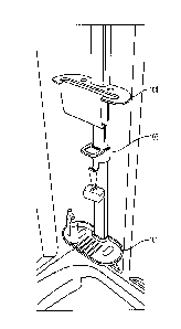
[0015] FIG. 1 shows a perspective view of a bath or shower wall having an
embodiment of the
integrated accessory rail shelving installed;
[0016] FIG. 2 shows a closer view of an embodiment of the integrated accessory
rail shelving;
[0017] FIG. 3 shows a closer view of another embodiment of the integrated
accessory rail
shelving;
[0018] FIG. 4 shows a front perspective view of a single installed storage
accessory in an
embodiment of the integrated accessory rail shelving;
[0019] FIG. 5 shows a side perspective view of a single installed storage
accessory in a
disengaged position in an embodiment of the integrated accessory rail
shelving;
[0020] FIG. 6 shows a rear perspective view of a single installed storage
accessory in an
embodiment of the integrated accessory rail shelving;
[0021] FIG. 7 shows a rear perspective view of a single storage accessory
prior to installation in
an embodiment of the integrated accessory rail shelving;
[0022] FIG. 8 shows a closer view of an engaging component in an embodiment of
the integrated
accessory rail shelving;
[0023] FIG. 9A-9D show various embodiments of locking shelving and storage
components
which may be used in an embodiment of the integrated accessory rail shelving.
[0024] FIG. 10 shows a rear view of the bath or shower wall in an embodiment
of the integrated
accessory rail shelving; and
4
CA 2973716 2017-07-14
[0025] FIG. 11 shows a top view of the rail in an embodiment of the integrated
accessory rail
shelving.
DETAILED DESCRIPTION OF THE INVENTION
[0026] A bath or shower wall system may be provided that allows for user-
determined positioning
of locking shower accessories along an integrated rail, rather than
predetermined accessory locations
in bath or shower wall surrounds. The users can determine the best locations
for the accessories to
afford a more ergonomic bathing or showering experience depending upon, for
example, the
individual height and reach of the user. The system has a variety of storage
solutions including
shelves, shallow trays, hooks and washcloth holders, for example.
[0027] With reference to FIG. 1, a bath or shower wall storage system
according to some
embodiments of the present invention includes one or more locking storage
accessories 100 that can
be placed in a customized location along a rail 1 located on a bath or shower
wall 10. In the
illustrated embodiments, the wall 10 may include an integrated rail 1 that is
formed as a protrusion
from the surface of the wall 10.
[0028] A typical bath or shower includes at least one wall surface that may
include shelving for
bath product storage. As shown in FIG. 1, a bath or shower wall 10 includes a
front surface 11
which faces into the bath or shower enclosure. The bath or shower wall 10 may
be made of
thermoformed acrylic or HIPS (High Impact Polystyrene), plastic, composite
material, ceramic, or
tile. In an embodiment, the bath or shower wall 10 may include one or more
integrated rails 1. One
or more locking storage accessories 100 may be placed at customized locations
on the rails 1, to hold
various items like bottles, soap bars, loofahs, washcloths, etc. Locking
components within the
locking storage accessory 100 allows for user-determined positioning and
repositioning of the
storage accessories by sliding the accessories 100 up and down the rail 1 that
is integrated with the
bath or shower wall 10, as discussed in more detail below.
[0029] FIG. 2 shows a closer view of one of the rails 1 on the bath or shower
wall 10. The rail 1
may be formed in the wall 10 so that it is vertical, and perpendicular to the
floor of the bath or
shower. It is understood by those in the art that the rail 1 may be formed in
the wall 10 so that is
horizontal, and parallel to the floor of the bath or shower, or alternatively
at an angle.
CA 2973716 2017-07-14
[0030] In an embodiment, the one or more locking storage accessories 100 may
include, for
example, a shallow tray 101, a soap shelf with grooves 102, and/or a hook 103.
As shown in FIG. 2,
each locking storage accessory 100 is clamped onto the protruding rail 1, so
that it is locked onto the
rail to support various bath products. FIG. 3 shows a closer view of another
embodiment of the rail
1, which includes a shallow tray 101, a hook 103, and a rod 104 for locking
storage accessories 100.
As with the locking storage accessories 100 in FIG. 2, each locking storage
accessory 100 of FIG. 3
is clamped onto the protruding rail 1, so that it is locked onto the rail to
support various bath
products. In this manner, the desired locking storage accessory 100 may be
placed along the rail 1 at
the desired height and in the desired order. The locking storage accessory 100
may be positioned
and repositioned as desired in a variety of configurations and at the
selection and discretion of the
user. One aspect of the invention allows for selection of the placement and/or
positioning of the
locking storage accessory 100 at any height along rail 1 that is integrated
with the bath or shower
wall 10.
[0031] In an embodiment, the rail 1 is integrated with the wall 10. As shown
in FIG. 4, in an
embodiment, the rail 1 includes a protruding portion 2 that is formed as part
of the wall 10. In an
embodiment, the rail 1 may be formed simply as a single protruding piece that
is formed as part of
the wall 10 and includes a front facing portion 3. In some embodiments, rail 1
is permanently
attached to wall 10. In some embodiments, rail 1 is integrally formed with
wall 10. Preferably, the
rail 1 is therefore formed of the same material as the wall 10. In an
embodiment, the rail 1 can also
include a capping portion that covers the protruding portion to form an
outward-facing portion of the
rail 1. In some embodiments, rail 1 is formed separately from wall 10 and
attached to wall 10 by a
user. In some embodiments, rail 1 is removably secured to wall 10 such that
rail 1 may be separated
from wall 10. In an embodiment, the wall 10 may include slots which allow for
the rail 1 to be
inserted into the wall 10 through the slots. It is understood by those in the
art that the size, shape,
and placement of the rail 1 may vary depending on the size, shape, and
configuration of the bath or
shower, so as to optimize the placement of locking storage accessories 100 in
desired locations
within the bath or shower.
[0032] In an embodiment, the rail 1 includes a groove 4 located on the sides
of the rail 1. The
locking storage accessory 100 also includes a recessed area 108 on one edge of
the storage accessory
which fits around the rail 1. In this manner, the locking storage accessory
100 may attach seamlessly
to the rail 1.
6
CA 2973716 2017-07-14
[0033] In some embodiments, each locking storage accessory 100 includes a
locking mechanism
for fixing the position of the locking storage accessory 100 on rail 1. In
some embodiments, the
locking mechanism can be transitioned between an unlocked position which
allows the locking
storage accessory 100 to slide along rail 1 and a locked position which
prevents the locking storage
accessory 100 from sliding relative to rail 1 FIGS. 5 and 6 show a locking
mechanism for the
locking storage accessories 100 in accordance with certain embodiments of the
present invention.
FIG. 5 shows the locking storage accessory 100 in an unlocked position, and
reveals a hinge clamp
110 of the locking storage accessory 100. In this manner, the locking storage
accessory 100 includes
a storage accessory portion (e.g. a shallow tray 101, soap dish 102, hook 103,
washcloth rod 104,
etc.) which is attached to a hinge clamp 110, so that the locking storage
accessory 100 and the hinge
clamp 110 fit together and the hinge clamp 110 nests within the locking
storage accessory 100. In
some embodiments, hinge clamp 110 nests within recessed area 108. The locking
storage accessory
100 is preferably made of injection molded plastic.
[0034] When the locking storage accessory 100 is placed in the unlocked
position (with the
locking storage accessory 100 angled upwards), as shown in FIG. 5, the locking
storage accessory
100 slides along the rail 1 freely. This allows for a user to slide the
locking storage accessory 100
along the rail to the desired position along the rail 1.
[0035] Once a user determines the desired position along rail 1, he/she pivots
the locking storage
accessory 100 down to compress the hinge clamp 110 against the rail 1, thereby
locking the position
of the locking storage accessory 100 at a fixed location on the rail 1. In
some embodiments, hinge
clamp 110 abuts against rail 1 and engages with groove 4 located on the sides
of rail 1 when the
locking storage accessory 100 is in a locked position. Likewise, to change the
position of the
locking storage accessory 100, the user can pivot the locking storage
accessory 100 upwards to
unlock the hinge clamp 110 and slide the storage accessory 100 along the rail
1 to a new location
and lock it in place. In this manner, the locking storage accessory 100 can
also be removed from the
wall 10 for easy cleaning.
[0036] FIG. 6 shows the locking storage accessory 100 in a locked position, in
an embodiment. In
the locked position, the locking storage accessory 100 wraps around the rail
1, and clamps onto the
groove 4 of the rail 1. In some such embodiments, locking storage accessory
100 is locked in place
with respect to rail 1 and is prevented from sliding along rail 1. In this
manner, the locking storage
7
CA 2973716 2017-07-14
accessory 100 sturdily grips to the rail 1, and provides storage support for
bath products placed on
the locking storage accessory 100.
100371 FIG. 7 displays the locking storage accessory 100 and hinge clamp 110
in more detail. In a
locked position, the hinge clamp 110 nests within a clamping portion 109 of
the locking storage
accessory 100. In this manner, when the locking storage accessory 100 is
tilted upwards to the
unlocked position, as seen in FIG. 5, the clamping portion 109 pivots away
from the hinge clamp
110 and releases the hinge clamp 110.
100381 In some embodiments, locking storage accessory 100 may be coupled to
hinge clamp 110
by a hinge component. In some embodiments, the hinge component is configured
to allow locking
storage accessory 100 to pivot relative to hinge clamp 110, for example, about
the one or more pivot
pins. As shown in FIG. 8, in an embodiment, the hinge clamp 110 includes two
pivot pins 111 on
either side of the hinge clamp 110. The pivot pins 111 are located within
corresponding holes in the
locking storage accessory 100, so that the locking storage accessory 100 may
rotate around the pivot
pin 111. The hinge clamp 110 includes a gripping portion 112 at the bottom
portion of the hinge
clamp 110. In an embodiment, the gripping portion 112 is formed by two slots
113 in the hinge
clamp 110, which allow for the gripping portion 112 to bend in an inwards
direction, separately from
the body of the hinge clamp 110. The slots 113 may define an upper boundary of
the gripping
portion 112. In some embodiments, the gripping portion 112 also includes
protrusions 115 on the
exterior surface of the gripping portion 112, which contact the clamping
portion 109 of the locking
storage accessory 100. In an embodiment, the gripping portion 112 also
includes gripping pads 114
on the interior surface of the gripping portion 112. These gripping pads 114
increase the friction
between the gripping portion 112 and the rail 1, to increase the sturdiness of
the locking storage
accessory 100 when in the locked position.
100391 In this manner, when the locking storage accessory 100 is placed in the
locked position, the
clamping portion 109 of the locking storage accessory 100 is pivoted downwards
around the hinge
clamp 110, and clamps down on the hinge clamp 110 by contacting the
protrusions 115 on the
gripping portion 112, and forcing the gripping portion 112 inwards. The
gripping pads 114 then
contact the rail 1, and the hinge clamp 110 clamps down on the rail 1, thus
locking the locking
storage accessory 100 in place. In some embodiments, pivoting the locking
storage accessory 100
upwards relative to hinge clamp 110 separates clamping portion 109 from
gripping portion 112,
which in turn allows gripping portion 112 to flex outward and unlock from rail
1.
8
CA 2973716 2017-07-14
[0040] In an embodiment, a plurality of locking storage accessories 100 may be
attached to a
single bath or shower wall 10. As seen in FIGS. 2 and 3, the locking storage
accessories 100 may
have a number of different sizes, shapes, and configurations to store various
bath products. For
instance, FIG. 9A shows an embodiment of the locking storage accessory 100,
soap dish 102 that
includes grooves on the shelf in order to store a bar of soap, a sponge, or
other products that require
air-drying on all surfaces. FIG. 9B shows an embodiment of the locking storage
accessory 100,
shallow tray 101 that includes a shallow tray to store items that may roll or
slip off a shelf. The tray
101 may include, for example, a vertical barrier surrounding one or more free
edges of the tray 101
that is configured to help retain items on the tray 101. FIG. 9C shows an
embodiment of the locking
storage accessory 100, washcloth rod 104 that includes a rod to hang a
washcloth. FIG. 9D shows
an embodiment of the locking storage accessory 100, hook 103 that includes one
or more hooks to
hang smaller items like razors, toothbrushes, and loofahs. It is understood by
those in the art that the
size and shape of the locking storage accessory 100 may be modified to
accommodate specific types
and sizes of bath products.
[0041] In an embodiment, a user who purchases the bath or shower wall system
may be provided
with a kit of locking storage accessories 100 of varying sizes and designs in
order to customize the
user's bath or shower storage. In an embodiment, additional accessories may be
offered to extend
the system and accommodate larger families or those with greater or particular
storage needs.
[0042] The formation of the rail, as integrated with the wall in an
embodiment, is shown in more
detail in FIGS. 10 and 11. The rail 1 may be formed by forming the wall 10
over one or more inserts
12. Thus, the wall 10 is formed such that the front surface 11 of the wall 10
is seamlessly integrated
with the rail 1. After the front surface 11 is formed over the insert 12, the
insert 12 is viewable on
the back surface 13 of the wall 10, as shown in Fig. 10. It is understood by
those in the art that the
shape and size of the rail 1 is defined by the shape and size of the insert
12. The insert may be
formed of any sturdy material, including wood, dense foam with a high heat
resistance, or plastic
with a high heat resistance.
[0043] As shown in FIG. 11, the rail 1 protrudes from the front surface 11 of
the wall 10 in a
protruding portion 2, but is integrated with the wall 10, such that there are
no seam lines. Further, the
rail is formed such that the rail 1 includes grooves 4 on either side of the
rail 1. In an embodiment,
the grooves 4 are formed such that the cross-section of the rail 1 includes an
S- shaped curve on
9
CA 2973716 2017-07-14
either side of the rail 1. This allows for the insert 12 to remain stationary
within the wall 10, as the
wider portion of the insert 12 cannot be removed through the grooves 4.
[0044] Only exemplary embodiments of the present invention and but a few
examples of its
versatility are shown and described in the present disclosure. It is to be
understood that the present
invention is capable of use in various other combinations and environments and
is capable of
changes or modifications within the scope of the inventive concept as
expressed herein.
[0045] Although the foregoing description is directed to the preferred
embodiments of the
invention, it is noted that other variations and modifications will be
apparent to those skilled in the
art, and may be made without departing from the spirit or scope of the
invention. Moreover, features
described in connection with one embodiment of the invention may be used in
conjunction with
other embodiments, even if not explicitly stated above.
CA 2973716 2017-07-14