Sélection de la langue

Search

Sommaire du brevet 2973738 

Énoncé de désistement de responsabilité concernant l'information provenant de tiers

Une partie des informations de ce site Web a été fournie par des sources externes. Le gouvernement du Canada n'assume aucune responsabilité concernant la précision, l'actualité ou la fiabilité des informations fournies par les sources externes. Les utilisateurs qui désirent employer cette information devraient consulter directement la source des informations. Le contenu fourni par les sources externes n'est pas assujetti aux exigences sur les langues officielles, la protection des renseignements personnels et l'accessibilité.

Disponibilité de l'Abrégé et des Revendications

L'apparition de différences dans le texte et l'image des Revendications et de l'Abrégé dépend du moment auquel le document est publié. Les textes des Revendications et de l'Abrégé sont affichés :

  • lorsque la demande peut être examinée par le public;
  • lorsque le brevet est émis (délivrance).
(12) Demande de brevet: (11) CA 2973738
(54) Titre français: SYSTEME D'ENCLIQUETAGE POUR CONTACTS ENFICHABLES
(54) Titre anglais: LATCHING MEANS FOR PLUG CONTACTS
Statut: Réputée abandonnée et au-delà du délai pour le rétablissement - en attente de la réponse à l’avis de communication rejetée
Données bibliographiques
(51) Classification internationale des brevets (CIB):
  • H01R 13/432 (2006.01)
(72) Inventeurs :
  • GRIEPENSTROH, SEBASTIAN (Allemagne)
(73) Titulaires :
  • HARTING ELECTRIC GMBH & CO. KG
(71) Demandeurs :
  • HARTING ELECTRIC GMBH & CO. KG (Allemagne)
(74) Agent: BORDEN LADNER GERVAIS LLP
(74) Co-agent:
(45) Délivré:
(86) Date de dépôt PCT: 2016-02-01
(87) Mise à la disponibilité du public: 2016-09-01
Requête d'examen: 2017-07-13
Licence disponible: S.O.
Cédé au domaine public: S.O.
(25) Langue des documents déposés: Anglais

Traité de coopération en matière de brevets (PCT): Oui
(86) Numéro de la demande PCT: PCT/DE2016/100042
(87) Numéro de publication internationale PCT: DE2016100042
(85) Entrée nationale: 2017-07-13

(30) Données de priorité de la demande:
Numéro de la demande Pays / territoire Date
10 2015 102 662.7 (Allemagne) 2015-02-25

Abrégés

Abrégé français

La présente invention concerne un système d'encliquetage pour des contacts enfichables (1) situés dans des boîtiers isolants (10) de connecteurs. Le système d'encliquetage selon l'invention comporte, outre la configuration connue de bras d'encliquetage (1) et d'épaulement d'encliquetage (2), un ergot d'encliquetage (3) situé sur l'épaulement d'encliquetage (2). L'ergot d'encliquetage (3) selon la présente invention permet d'éviter une libération de l'encliquetage sous l'effet d'une charge mécanique. Ledit ergot d'encliquetage (3) permet un encliquetage supplémentaire du bras d'encliquetage (1) avec le contact enfichable (5).


Abrégé anglais

The invention relates to a latching means for plug contacts (1) in insulating housings (10) of plug connectors. The invention relates to a latching means which, in addition to the known arrangement of latching arm (1) and latching shoulder (2), comprises a latching lug (3) on the latching shoulder (2). By means of the latching lug (3) according to the invention, release of the latching means under mechanical load is avoided. The latching lug (3) permits additional latching of the latching arm (1) on the plug contact (5).

Revendications

Note : Les revendications sont présentées dans la langue officielle dans laquelle elles ont été soumises.


Claims:
1. A latching mechanism for plug contacts (5), comprising at
least one latching arm (1) arranged in an insulating
housing (10), wherein the latching arm (1) has a fixed end
and a free end,
wherein the latching arm (1) forms a latching shoulder (2)
at its free end,
characterized in that
a latching lug (3) is formed on the latching shoulder (2).
2. The latching mechanism for plug contacts (5) as claimed in
claim 1,
characterized in that
the latching shoulder (2) is aligned approximately
perpendicularly to the alignment of the latching arm (1).
3. The latching mechanism for plug contacts (5) as claimed in
one of claims 1 or 2,
characterized in that
the latching lug (3) is aligned in the direction of the
fixed end of the latching arm (1).
4. The latching mechanism for plug contacts (5) as claimed in
one of the preceding claims,
characterized in that
the latching arm (1) together with the latching shoulder
(2) and the latching lug (3) form a groove (4).
5. The latching mechanism for plug contacts (5) as claimed in
claim 2,
characterized in that
the groove (4) is provided for receiving the plug contact
(5) .
7

6. The latching mechanism for plug contacts (5) as claimed in
one of the preceding claims,
characterized in that
the latching arm (1), the latching shoulder (2) and the
latching lug (3) together surround at least part of an
assembled plug contact (5).
7. The latching mechanism for plug contacts (5) as claimed in
one of the preceding claims,
characterized in that
the latching arm (1) is formed to be resilient so that the
free end is movable relative to the fixed end.
8

Description

Note : Les descriptions sont présentées dans la langue officielle dans laquelle elles ont été soumises.

CA 02973738 2017-07-13
Latching means for plug contacts
The invention starts with a latching mechanism for plug contacts
according to the precharacterizing clause of the independent
claim 1.
Latching mechanisms of this type are needed for latching plug
contacts in insulating bodies of plug connectors and for
securing them therein. By latching the contacts, further
fastening of the plug contacts in the insulating body is no
longer necessary. Automatic latching of this type saves time and
money during assembly, which can be undertaken without the aid
of tools.
DE 10 2006 004 782 B4 discloses an insulating body of this type
for receiving plug contacts. In this, latching arms having
latching shoulders are produced by means of two mutually
engaging molded cores. The latching shoulders of the latching
arms project into the insulating body such that an inserted plug
contact latches behind them.
DE10 2009 053 778 Al presents an electrical plug connector which
is formed to be plugged together with a complementary plug
connector and has corresponding latching members for this.
DE 10 2011 087 243 B3 presents an electrical plug connector
which has a contact securing means. The contact securing means
here has at least one elastic contact lance which latches in the
interior of the plug connector.
Latching mechanisms of this type are disadvantageous in that the
latching shoulder is only held in position for the latching of
the plug contact by the spring force of the latching arm. For
dismantling purposes, for example, as a result of deflecting the
1

CA 02973738 2017-07-13
latching arm by means of a tool, the latching shoulder can
release the plug contact and the latter can be removed.
However, a deflection of the latching arm can be effected not
only by a tool, but also under the influence of an increased
force on the plug contact itself. If this acts on the latching
shoulder and a rotation occurs at the same time, the resultant
force generates a deflection of the latching arm and therefore
releases the plug contact unintentionally.
The object of the invention therefore consists in designing the
latching mechanism for plug contacts such that the disadvantages
known from the prior art can be eliminated. Plug contacts should
also remain reliably latched under the forces and moments which
occur.
The object is achieved by the characterizing features of the
independent claim 1.
Advantageous embodiments of the invention are revealed in the
subclaims.
The invention relates to a latching mechanism for plug contacts
of plug connectors. The latching mechanism is received in an
insulating housing in which the plug contacts can be inserted.
The housing has at least one contact opening which serves to
receive a plug contact. Depending on the type of plug connector,
the insulating housing forms the plug connector housing directly
or is in turn received in a plug connector housing.
The latching mechanism is formed by at least one latching arm,
which projects into the at least one contact opening of the
housing. The latching arm is preferably produced in one piece
with the insulating body. The latching arm here has a fixed end
with which it is fastened in the contact opening. The second end
2

CA 02973738 2017-07-13
of the latching arm forms a free end which is movable against
the spring stiffness of the latching arm.
A latching shoulder is provided at the free end of the latching
arm. The latching shoulder is aligned at an approximate right
angle to the latching arm and projects into the contact opening
such that an inserted plug contact can latch behind it. The plug
contact preferably latches by means of a cable-connection side
behind the latching shoulder. To this end, the plug contact is
guided completely past the latching shoulder as it is inserted
into the contact opening. As a result of an insertion chamfer on
the latching shoulder, this latter is pushed away laterally in
opposition to the spring force of the latching arm by the plug
contact. Behind the plug contact, the latching shoulder latches
behind the plug contact again as a result of the spring force of
the latching arm and secures this plug contact against being
pulled out.
According to the invention, an additional latching lug is formed
on the latching shoulder. This latching lug is aligned in the
direction of the fixed end of the latching arm. The latching lug
is designed such that it engages in a cable receiving opening of
the plug contact. The latching arm, the latching shoulder and
the latching lug thereby together surround at least one region
of the cable receiving opening of the plug contact.
As a result of this expedient arrangement, it is only possible
to deflect the latching arm when the plug contact is not
touching the latching shoulder. In this case, the latching lug
would prevent a deflection of the latching arm. The plug contact
is located in a pocket which is formed by the latching arm, the
latching shoulder and the latching lug. It is only through the
brief further insertion of the plug contact into the contact
opening that the plug contact releases the latching lug and an
opening of the latching mechanism is possible.
3

CA 02973738 2017-07-13
The present invention solves the problem posed at the outset in
that, as a result of a latching arm, which can only be deflected
and release a plug contact when the plug contact does not exert
a force on the latching shoulder. Instead, the deflection of the
latching arm becomes more difficult as the force effect on the
latching shoulder increases.
Exemplary embodiment
An exemplary embodiment of the invention is illustrated in the
drawings and explained in more detail below. The drawings show:
Fig. 1
a latching mechanism for plug contacts as known from
the prior art;
Fig. 2 a latching mechanism for plug contacts according to
the present invention;
Fig. 3 a three-dimensional
illustration of a latching
mechanism for plug contacts as known from the prior
art; and
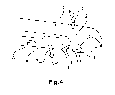
Fig. 4 a three-dimensional illustration of a latching
mechanism for plug contacts according to the present
invention.
The figures contain partially simplified
schematic
illustrations. Identical reference numerals are sometimes used
for elements which are similar, but maybe not identical.
Different views of the same elements could be shown on a
different scale.
Figure 1 shows a detail of a sectional illustration through a
plug connector, having a latching mechanism for a plug contact 5
as known from the prior art. The insulating housing 10 of the
plug connector forms a contact opening (upper region of the
figure) into which the plug contact 5 is inserted.
4

CA 02973738 2017-07-13
A resilient latching arm 1 is furthermore formed in one piece on
the insulating housing 10. The latching arm 1 is designed to be
resilient so that a free end of the latching arm 1 is movable
relative to a fixed end. The free end of the latching arm 1 is
provided with a latching shoulder 2. The latching shoulder 2
projects into the contact opening, linearly flush with the
deflection direction of the free end of the contact arm 1.
The received plug contact 5 latches by means of a cable-
receiving side 6 behind the latching shoulder 2. A pulling out
of the plug contact in the direction of the latching shoulder is
only possible through a deflection of the entire latching arm 1.
A latching mechanism for a plug contact 5 according to the
present invention is illustrated in figure 2 in the same view as
in figure 1. The embodiment corresponds for the most part to
that of figure 1. According to the invention, a latching lug 3
is provided on the latching shoulder 2. The latching lug 3 is
aligned along the latching arm 1 in the direction of the fixed
end thereof.
As a result of the alignment of the latching lug 3, this forms a
groove 4 together with the latching shoulder 2 and the latching
arm 1. As can be seen in figure 2, the end of the cable-
receiving side 6 of the plug contact 5 is received in the groove
4. A deflection of the latching arm 1 is now impossible as a
result of the latching lug 3.
The latching lug 3 prevents a deflection by engaging in the
cable-receiving side 6 of the plug contact. To enable a
deflection and therefore the release of the plug contact 5, this
firstly has to be pushed further into the contact opening of the
insulating housing 10 until the latching lug 3 is released.

CA 02973738 2017-07-13
The latching mechanism according to figure 1, which is known
from the prior art, is illustrated again in figure 3 in a three-
dimensional detail view. The disadvantages of this solution are
shown here. As a result of two forces being introduced onto the
plug contact 5, this can be freed from the latching mechanism.
If the plug contact 5 is pushed in the direction of the latching
shoulder 2 by means of a force A, a radial force C is exerted on
the latching shoulder 2 and latching arm 1 as a result of the
force from the plug contact 5 on the latching shoulder 2.
However, owing to the friction between the plug contact 5 and
the latching shoulder 2, this force C is not great enough to
deflect the latching arm 1. However, if a rotational movement of
the contact 5 is additionally generated by a moment B, the
dynamic friction between the plug contact 5 and the latching
shoulder 2 is considerably lower and the latching arm 1 is
deflected by the force C. The latching mechanism can be freed as
a result of this force C and the plug contact 5 can be released
unintentionally.
This unintentional effect is prevented by the solution according
to the invention. This is illustrated again accordingly in
figure 4. A force C is likewise generated by the force A in
conjunction with the moment B. However, this force C is absorbed
by the latching lug 3. The latching lug 3 therefore latches the
latching arm 1 against the plug contact 5. The latching of the
plug contact 5 is therefore prevented from being freed
unintentionally.
6

Dessin représentatif
Une figure unique qui représente un dessin illustrant l'invention.
États administratifs

2024-08-01 : Dans le cadre de la transition vers les Brevets de nouvelle génération (BNG), la base de données sur les brevets canadiens (BDBC) contient désormais un Historique d'événement plus détaillé, qui reproduit le Journal des événements de notre nouvelle solution interne.

Veuillez noter que les événements débutant par « Inactive : » se réfèrent à des événements qui ne sont plus utilisés dans notre nouvelle solution interne.

Pour une meilleure compréhension de l'état de la demande ou brevet qui figure sur cette page, la rubrique Mise en garde , et les descriptions de Brevet , Historique d'événement , Taxes périodiques et Historique des paiements devraient être consultées.

Historique d'événement

Description Date
Le délai pour l'annulation est expiré 2019-02-01
Demande non rétablie avant l'échéance 2019-02-01
Réputée abandonnée - omission de répondre à un avis sur les taxes pour le maintien en état 2018-02-01
Inactive : Page couverture publiée 2017-09-13
Inactive : CIB enlevée 2017-09-12
Inactive : CIB en 1re position 2017-09-12
Inactive : CIB attribuée 2017-09-12
Lettre envoyée 2017-09-11
Inactive : Acc. récept. de l'entrée phase nat. - RE 2017-09-11
Inactive : CIB attribuée 2017-07-21
Demande reçue - PCT 2017-07-21
Exigences pour une requête d'examen - jugée conforme 2017-07-13
Toutes les exigences pour l'examen - jugée conforme 2017-07-13
Exigences pour l'entrée dans la phase nationale - jugée conforme 2017-07-13
Demande publiée (accessible au public) 2016-09-01

Historique d'abandonnement

Date d'abandonnement Raison Date de rétablissement
2018-02-01

Historique des taxes

Type de taxes Anniversaire Échéance Date payée
Requête d'examen - générale 2017-07-13
Taxe nationale de base - générale 2017-07-13
Titulaires au dossier

Les titulaires actuels et antérieures au dossier sont affichés en ordre alphabétique.

Titulaires actuels au dossier
HARTING ELECTRIC GMBH & CO. KG
Titulaires antérieures au dossier
SEBASTIAN GRIEPENSTROH
Les propriétaires antérieurs qui ne figurent pas dans la liste des « Propriétaires au dossier » apparaîtront dans d'autres documents au dossier.
Documents

Pour visionner les fichiers sélectionnés, entrer le code reCAPTCHA :


Pour visualiser une image, cliquer sur un lien dans la colonne description du document. Pour télécharger l'image (les images), cliquer l'une ou plusieurs cases à cocher dans la première colonne et ensuite cliquer sur le bouton "Télécharger sélection en format PDF (archive Zip)" ou le bouton "Télécharger sélection (en un fichier PDF fusionné)".

Liste des documents de brevet publiés et non publiés sur la BDBC .

Si vous avez des difficultés à accéder au contenu, veuillez communiquer avec le Centre de services à la clientèle au 1-866-997-1936, ou envoyer un courriel au Centre de service à la clientèle de l'OPIC.


Description du
Document 
Date
(aaaa-mm-jj) 
Nombre de pages   Taille de l'image (Ko) 
Abrégé 2017-07-12 1 15
Description 2017-07-12 6 254
Dessins 2017-07-12 2 43
Revendications 2017-07-12 2 42
Dessin représentatif 2017-07-12 1 10
Accusé de réception de la requête d'examen 2017-09-10 1 174
Rappel de taxe de maintien due 2017-10-02 1 111
Avis d'entree dans la phase nationale 2017-09-10 1 201
Courtoisie - Lettre d'abandon (taxe de maintien en état) 2018-03-14 1 172
Rapport de recherche internationale 2017-07-12 3 76
Modification - Abrégé 2017-07-12 1 70
Demande d'entrée en phase nationale 2017-07-12 3 90