Note : Les descriptions sont présentées dans la langue officielle dans laquelle elles ont été soumises.
CA 02975082 2017-07-26
WO 2016/122366 PCT/SE2015/051026
1
MULTIPLE DOSING DEVICE AND MAGAZINE
Technical Field
The present invention concerns a multiple dosing device and magazine, to be
used for mixing additives with a fluid.
Background
The multiple dosing device has been developed for milk powder, especially
baby formula milk powder, but it could be used for other powder-like additivi
es or
pellet-like additives such as coffee, tea, chocolate, medicine, vitamines etc.
to be mixed
with a fluid. Thus, the invention is generally directed to a device for mixing
an additive
with a fluid before drinking
For many additives it is important that the additive is held in a sealed
condition
before use. If the additive gets wet before use it may not be useable.
Today it is common to take for instance baby formula milk powder from a can
in a measured quantity. Said measurement is often made by hand and can be
quite
cumbersome and is not always accurate. Further, the baby formula milk powder
left in
the can risk deteriorating due to exposure to the surrounding air.
Summary
In view of the above, one object of the present invention is to facilitate
measuring and delivering of exact quantities of additive at the same time as
deteriorating of not yet used additive is hindered.
According to one aspect of the invention, a multiple dosing device is provided
for releasing one or more doses of powder or additive. The device comprises a
magazine, having a number of through openings receiving a tube each. The tubes
contain a dose of additive each. The through openings and the tubes extended
axially
between two opposite ends of the magazine. The tubes are arranged moveable in
an
axial direction inside respective through opening. The device further
comprises an
activation part having push buttons. The push buttons are placed for
controlling the
axial position of one tube each.
A further aspect of the present invention is that the same type of magazine
should be possible to use for many different additives, irrespectively of
their
2
Attorney Ref.: 1099P026CA01
consistency. By having only one, or a few, types of magazine handling of the
magazines
are facilitated. This refers to manufacture, filling etc.
Even though the invention is mainly described in connection with milk powder,
a person skilled in the art realises that it may be used for other additives
to be mixed
with a fluid before consumption.
In one embodiment the magazine is placed in an automatic brewer, such as a
coffee making machine adapted to receive the magazine. The strength of the
coffee may
be adjusted by the number of tubes chosen for release of the coffee.
Further objects and advantages of the present invention will be obvious to a
person skilled in the art when reading the detailed description below.
In another aspect, this document discloses a multiple dosing device for
releasing one or more doses of an additive, the multiple dosing device
comprising: a
magazine having a number of through openings each receiving a tube, wherein
the tubes
are open at both ends and each tube contains a dose of the additive; and an
activation
part, wherein the through openings and the tubes extend axially between two
opposite
ends of the magazine, wherein the tubes are arranged to be moveable in an
axial
direction inside the respective through openings, wherein an upper foil and a
lower foil
are placed adhered to the opposite ends of the magazine, wherein the ends of
the tubes
are placed abutting or adjacent the upper foils and the lower foils,
respectively, wherein
each tube has a pointed lower end for penetrating the lower foil, wherein the
activation
part has means to break the upper foil, wherein the activation part has push
buttons,
wherein the push buttons are placed for controlling an axial position of one
tube each,
wherein each push button has a pointed lower end for penetrating the upper
foil,
wherein each push button is arranged to move the tube of the magazine from a
non-
activated position to an activated position releasing the dose of the additive
of the tube,
and wherein each push button, when activated, continues moving inside the
corresponding tube.
Brief Description of the Drawings
The invention will be explained further below by way of example and with
reference to the enclosed drawings. In the drawings:
Fig. 1 is a perspective view of a magazine according to the present invention,
Fig. 2 is an exploded view of the magazine of Fig. 1,
Date Recue/Date Received 2022-05-18
2a
Attorney Ref.: 1099P026CA01
Fig. 3 is a perspective view of a multiple dosing device, comprising the
magazine of Figs. 1 and 2,
Fig. 4 is a cut perspective view of the multiple dosing device of Fig. 3,
including an enlarged part,
Fig. 5 is a partly cut perspective view of an adapter mounted to the multiple
dosing device of Figs. 3 and 4.
Fig. 6 and 7 are perspective views of an alternative multiple dosing device,
and
Fig. 8 is a perspective view, partly cut, of a coffee making machine using a
multiple dosing device.
Detailed Description
As used in this description the expressions "upper", "lower", "axial",
"radial"
and corresponding expressions are in relation to the device as shown in
respective Fig.
and the position of the device in normal use.
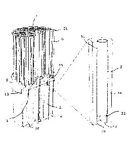
The multiple dosing device has a magazine 1, receiving a number of tubes 2
open at both ends, and an activation part 5, placed on one side of the
magazine 1.
The magazine 1 has the form of a cylinder and has a number of through
openings 10. The through openings 10 extend in axial direction between
opposite ends
Date Recue/Date Received 2022-05-18
CA 02975082 2017-07-26
WO 2016/122366 PCT/SE2015/051026
3
of the magazine 1. An upper foil 3 and a lower foil 4 are placed at opposite
ends of the
magazine 1, covering both ends of each through opening 10.
A tube 2 is placed in each through opening 10. The tubes 2 are arranged
moveable in an axial direction inside respective through opening 10 receiving
a tube 2.
Each tube 2 is moveable between a non-activated, upper position and an
activated,
lower position. Each tube 2 has a pointed lower end 14. The pointeed lower end
14 is
given in that the lower end is inclined from one side of the tube to the
diametrically
opposite side of the tube 2. The ends of each tube 2 will abut the upper and
lower foils
3, 4 respectively, or be placed adjacent the upper and lower foils 3, 4. In
some
embodiments there is no tube in one of the through openings 10 of the magazine
1.
Often the through opening 10 having no tube is a central through opening 10.
Such a
through opening 10 having no tube may be used for delivery of a fluid. The
tubes 2 are
filled with an additive, such as milk powder. Further, an upper protective
cover 8 and a
lower protective cover 9 are arranged at opposite ends of the magazine 1.
Normally the
additive is filled into the tubes 2 with the tubes 2 in place in the magazine
1.
The activation part 5 has a number of push buttons 6. The function of the
activation part 5 and the push buttons 6 will be discussed further below. A
protective
cover 30 is placed on the activation part 5, covering the push buttons 6. A
person
skilled in the art realizes that the number of tubes 2 received inside the
magazine 1 may
vary, depending on the specific intended use and the size of the appropriate
doses.
The tubes 2 and corresponding through openings 10 of the magazine 1 are
shown having a circular cross section. However, a person skilled in the art
realises that
the tubes and corresponding through openings may have other cross section
forms, such
as oval, honeycomb or other polygonal forms. Also the magazine 1 may have
other
forms than cylindrical.
The magazine 1 is in one embodiment made of a plastic material with a sealing
material placed on the outer surface of the magazine 1 and which sealing
material
connects to the upper and lower foils 3, 4. The sealing material may be a foil
of plastic
material or metallic material, such as aluminium. In another embodiment the
magazine
1 has a sealing material inmoulded in the outer wall. In a further embodiment
each tube
2 is metallised to give the sealing effect. In still a further embodiment the
magazine 1 is
made of cardboard with a sealing material on the inside.
The activation part 5 has the form of a ring. The push buttons 6 are received
in
through openings of the activation part 5 and project from an upper edge of
the
activation part 5, in non-activated positions. The push buttons 6 have a disc
21 at an
CA 02975082 2017-07-26
WO 2016/122366 PCT/SE2015/051026
4
upper end. The outer diameter of the disc 21 exceeds the inner diameter of the
through
openings of the activation part 5 receiving the push buttons 6. In an
activated position
for each push button 6 the disc 21 of the push button 6 will abut the upper
surface of the
activation part 5. Each push button 6 is to act on a single tube 2 in the
magazine 1.
Thus, the push buttons 6 are given positions corresponding to the position of
the tubes 2
in the magazine 1. Each push button 6 has a pointed lower end 15. In a non
activated
position the pointed lower end 15 of the push button 6 abuts or is placed
adjacent the
upper foil 3. The activation part 5 is pressed down on one end of the magazine
1 and is
held in placed by means of co-operating ridges 11, 13 on the magazine 1 and
activation
part 5, respectively. In another embodiment the activation part is assembled
to the
magazine by means of co-operating threads.
A support 7 is placed in a central position of the activation part 5. Said
support
7 is to support the protective cover 30, in order to hinder unwanted
activation of any
push button 6 when the protective cover 30 is in place. The support 7 has the
form of a
tube in some embodiments, for delivery of a fluid. Such a support 7, having
the form of
a tube, is placed in a position over a through opening 10 of the magazine I
having no
tube. In some embodiments there is no support, wherein a pipe for delivery of
fluid can
be inserted directly into a through opening 10 of the magazine 1 having no
tube.
It is possible to reuse the activation part 5. It will then be removed from
the
magazine 1 when all tubes 2 have been emptied and then placed on a new
magazine 1
having filled tubes 2. The push buttons 6 are returned to their non-activated
positions,
when hitting the upper foil 3.
The upper and lower foils 3, 4 are adhered to the ends of the magazine 1, in
that the foils 3, 4 adhere to a solid part 16 of the magazine 1 between the
openings 10 of
the magazine 1. The foils 3, 4 are adhered to the ends of the magazine 1 by
means of
glue or welding. As stated above the ends of the tubes 2 will abut the upper
and lower
foils 3, 4, respectively, or be placed adjacent the upper and lower foils 3,
4.
In one embodiment the magazine 1 is mounted to a bottle 19 by means of an
adapter 17. The bottle 19 may be a feeding bottle. The adapter 17 is fastened
to the
magazine 1 by means of inner protruding parts of the adapter 17 received in
grooves 12
at the lower end of the magazine 1. A person skilled in the art realises that
the adapter
17 and the magazine 1 may be assembled to each other in other ways than as
indicated
above. It may for instance be by means of protruding parts of the magazine 1
received
in grooves of the adapter 17 or by co-operating threads of respective part. In
the shown
embodiment the adapter 17 is mounted to the bottle 19 by means of co-operating
CA 02975082 2017-07-26
WO 2016/122366
PCT/SE2015/051026
threads 18, 20 of the adapter 17 and bottle 19, respectively. The threads 20
of the bottle
19 are the threads normally used for receiving a cap of the bottle 19.
In use the magazine 1 is placed to be able to release an additive from one or
more of the tubes 2 to a suitable container. If for instance an adapter, as
indicated in Fig.
5 .. 5, is used, the lower protective cover 9 of the magazine 1 is removed
before the
magazine 1 is mounted to the adapter 17. The adapter 17 is mounted to the
bottle 19
either before the magazine 1 is mounted to the adapter 17 or with the magazine
1
already mounted to the adapter 17. The bottle 19 is furnished with a suitable
fluid for
receiving an additive form the magazine 1. Said fluid is often water. Before
mounting of
the activation part 5 to the magazine 1, the upper protective cover 8 of the
magazine 1 is
removed. With the activation part 5 mounted to the magazine 1, one or more of
the
protruding push buttons 6 are pressed down, whereby the pointed lower end 15
of each
push button 6 will go through the upper foil 3. In one embodiment the upper
foil 3 is
weakened in the area of the pointed lower end 15 to facilitate penetration of
the upper
foil 3. The weakness may be given by grooves that not fully go through the
upper foil 3.
The grooves may be placed in the form of a part of a circle, wherein no
grooves are
placed in the part of the circle opposite the part to receive the pointed
lower end 15 of
the corresponding push button 5. The penetration is also facilitated by means
of the
upper foil 3 being adhered to the solid part 16 of the magazine 1, as stated
above By
means of the weaknesses in form of parts of circles and the adherence to the
solid part
16 of the magazine, the risk that any part of the upper foil 3 will be torn
away and
follow the released additive into the fluid of the bottle 19 is minimized. In
a further
embodiment the upper foil 3 is pre-tensioned in such a way that it will
automatically
withdraw from the formed opening.
As a push button 5 is pressed downwards penetrating the upper foil 3, it will
push the tube 2 placed below it downwards. Thereby the lower pointed end 14 of
said
tube 2 will penetrate the lower foil 4. In the same way as discussed above the
lower foil
4 may have grooves placed in the form of a part of a circle giving a weakness
to
facilitate penetration. In the same way as for the upper foil 3, the partly
circular
weaknesses of the lower foil 4 and the adherence of it to the solid part 16 of
the
magazine 1, or pre-tension of the lower foil 4 will minimize the risk that
parts of the
lower foil 4 will be torn away and risk ending up in the fluid of the bottle
19. When the
lower pointed end 14 of a tube 2 has penetrated the lower foil 4, the additive
inside said
tube 2 will be released and go down into the bottle 19 via the adapter 17.
CA 02975082 2017-07-26
WO 2016/122366 PCT/SE2015/051026
6
In order to hinder that the tube 2 is ejected from the magazine 1, a stop ring
22
is placed on the outer surface of the tube 2, a distance above the lower end
corresponding with the desired maximal movement for the tube 2. Said stop ring
22 is
to abut an inner edge 23 at the lower end of the through opening 10 to stop
the
movement of the tube 2. Thus, the stop ring 22 and the lower edge 23 co-
operate to
define the activated position of the tube 2. The stop ring 22 may be a
separate part fixed
to the tube 2 or may be formed as a bead on the tube 2.
In the embodiment of Figs. 3 to 5 the push buttons 6 will be pressed all the
way
through respective tube 2 in order to positively eject the additive from the
tube 2. As
indicated in the enlargement of Fig. 4, the upper end of each through opening
10 has a
smaller diameter. In the starting, non-activated position the upper end of
each tube 2 is
pressed into the upper end of the opening 10. Each push button 6 has an outer
diameter
slightly larger than the inner diameter of the upper end of the tube 2, when
said upper
end is placed in the part 31 of the opening 10 having a smaller diameter. When
the press
button 6 is activated it will therefore press the tube 2 downwards in the
through opening
10. When the upper end of the tube has left the part 31 of the opening 10
having smaller
diameter, the tube 2 will flex outwards. The distance for the part 31 of the
through
opening 2 having smaller diameter corresponds with the distance between the
stop ring
22 and the lower edge of the tube 2. The outer diameter of each push button 6
is
somewhat smaller than the inner diameter of the tube 2, when the tube 2 has
left the part
31 of the opening 10 having smaller diameter. By means of this arrangement the
push
button 6 will press the tube 2 downwards until the stop ring 22 hits the edge
23 at the
lower end of the opening 10 at the same time as the upper end of the tube 2
flex
outwards as it leaves the part 31 of the opening 10 having smaller diameter.
The push
button 6 will then continue its movement downwards inside the tube 2, which
tube 2
now is at a standstill.
A person skilled in the art realises that the arrangement between the push 6
buttons and respective tubes 2 to first push down the tube 2 and then let the
push button
6 continue inside the tube 2 may be accomplished in different ways. In an
alternative
embodiment the push button will look somewhat like a syringe, with a lower
part
having an outer diameter larger than the outer diameter of the tube, for
pressing the tube
downwards until the stop ring of the tube hits the lower edge of the through
opening. A
second part of the "syringe" is arranged axially moveable in relation to the
first part and
will go down into the tube. In this case there is no need for a smaller
diameter of the
through opening at the upper end. In a further alternative embodiment the tube
2 has the
CA 02975082 2017-07-26
WO 2016/122366 PCT/SE2015/051026
7
same inner diameter throughout its entire length. A membrane is thereby placed
at the
upper end of the tube 2. The force needed to break said membrane is larger
than the
force needed to break the lower foil 4. When the push button 6 is activated it
will first
press on the membrane, without breaking it, pushing the tube 2 downwards
inside the
magazine 1, whereby the pointed lower end 15 of the push button 6 will break
the lower
foil 4. When the movement of the tube 2 downwards is stopped by means of the
stop
ring 22, the pointed lower end 15 of the push button 6 will break the membrane
and
continue its movement downwards inside the tube 2.
If more than one dose of an additive is to be released the number of push
buttons 6 corresponding with the desired dose is pressed down.
The push buttons 5 stay in the lowered positions after the additive in
corresponding tubes 2 has been released. It is therefore easy to establish how
many
doses are left in the magazine 1. One only counts the number of push buttons 5
in non-
activated positions.
In the embodiment of Figs. 6 and 7, the multiple dosing device comprises a
magazine Ito which an activation part 24 in the form of a ring is mounted. The
activation part 24 has push buttons 26 and a central support 27 for a
protective cover 25
of the activation part 24. The axial length of each push button 26 of the
activation part
24 is relatively short compared to the previously described embodiment. In the
same
way as for the previously described activation part 5, the central support 27
has the form
of a tube in some embodiments, for delivery of a fluid. Such a support 27,
having the
form of a tube, is placed in a position over a through opening 10 of the
magazine 1
having no tube. In some embodiments there is no support, wherein a pipe for
delivery of
fluid can be inserted directly into a through opening 10 of the magazine
having no tube.
The embodiment of Figs. 6 and 7 is intended for an additive which will be
released by means of gravitation. Depending on the consistencyof the additive,
such as
grain size and greasiness, and the characteristics of the tubes 2, such as
inner diameter
and cross section form, the gravitation may not suffice to release the
additive from the
tubes 2. The previously described embodiment, having relatively long push
buttons 6 is
intended for use with such additives.
Also in the embodiment of Figs. 6 and 7 the push buttons 26 have pointed
lower ends, to go through the upper foil 3 of the magazine 1. Thus, when a
push button
26 is activated it will go through the upper foil 3 and press the tube 2,
placed below it
through the lower foil 4 of the magazine 1. The tube 2 will be pressed
downwards until
the stop ring 22 hits the edge 23 of the opening 10. The additive inside the
tube 2 will
CA 02975082 2017-07-26
WO 2016/122366 PCT/SE2015/051026
8
then be released through gravitation. The push buttons 26 of this embodiment
are not
intended to go all the way through corresponding tubes 2.
For magazines 1 having a central through opening having no tube or where a
support 7, 27 in the form of a tube is used, a hot or cold fluid may be
delivered via said
.. opening or support 7, 27 in the form of a tube into the bottle 19 after or
before the
aditive is released. A pipe is then inserted in the through opening,
penetrating the upper
and lower foils 3, 4. The fluid is then furnished to the bottle 19 via said
pipe. It is also
possible to break the upper and lower foils 3, 4 at the opposite ends of the
through
opening by means of an appropriate tool and then lead the fluid down into the
bottle 19
via the through opening. Hot or cold fluid can be provided via such a central
through
opening having no tube for instance in connection with baby formula milk
powder,
coffee, tea or any other additive.
When the additive has been released the adapter 17 and multiple dosing device
is removed from the bottle 19. The adapter 17 may be reused.
A magazine of a multiple dosing device according to the present invention may
be used for different types of additives, as indicated above In Fig. 8 a
coffee making
machine 28 is indicated. The coffee making machine 28 is only shown as one
example
of an automatic brewer. A magazine 29, corresponding with previously described
magazines, is placed in the coffee making machine 28. In this case the
automatic brewer
as such forms the activation part of the multiple dosing device. Thus the
automatic
brewer will have means to break the upper foil 3 of the magazine 1, and to
push the
tubes 2 downwards to break the lower foil 4 of the magazine. The means to
break the
upper foil 3 and to push the tubes 2 downwards, are either controlled by the
automatic
brewer or are controlled manually by the user. In a way corresponding to the
embodiment of Fig. 5, an adapter 17 is placed between the lower end of the
magazine 1
and an upper end of a bottle 19. The fluid, such as hot water, may be
distributed directly
to the bottle 19 by means of a pipe 32 of the brewer 28 The pipe 32 is
received in a
central through opening 10 of the magazine 1 having no tube. The upper and
lower foils
3, 4 of the magazine 1 are broken by means of the pipe 32. It is also possible
to break
the upper and lower foils 3, 4 at the opposite ends of the through opening 10
by means
of an appropriate tool and then lead the fluid down into the bottle 19 via the
through
opening 10. The additive to the fluid is delivered from one or more tubes 2 of
the
magazine 1, either before or after the fluid or at the same time as the fluid.
The order of
deliverance of the fluid and the additive depends on the type of additive and
the fluid. A
CA 02975082 2017-07-26
WO 2016/122366 PCT/SE2015/051026
9
person skilled in the art realises that this kind of brewer may be used for
other additives
than coffee or tea.
In automatic brewers water may be feed directly through a tube 2. The upper
foil 3 of the magazine is thereby broken by the brewer, either by a pipe for
delivery of
the water or by a separate pointed part, such as one or more needles. The
motion for the
tube 2 will then be accomplished by the pressure of the water. By means of
said
pressure of water, the pointed lower end 14 of the tube 2 will break the lower
foil 4. In
the bottom of the tube 2 a sieve may be placed in order to hinder an additive,
such as
coffee, to be released from the tube 2. The movement of the tube 2 will be
stopped by
the co-operation between the stop ring 22 and the edge 23 of the opening 10.
The tubes
2 having a sieve at the lower end are mainly intended for coffee or tea.
The activation part 5 and the adapter 17 may be reused. It is therefore enough
for a consumer to purchase a magazine 1 with filled tubes 2 when a previous
magazine
1 has been emptied.
The magazine 1 together with a mounted activation part 5, 24 may be fixed to a
stand, in which case it may suffice to hold a bottle, such as a feeding
bottle, directly
under the magazine 1. A person skilled in the art realises that such a stand
may have
many different designs. The magazine 1 and activation part 5, 24 is mounted to
the
stand in any suitable way such as by screws or snap fastenings.