Note : Les descriptions sont présentées dans la langue officielle dans laquelle elles ont été soumises.
CA 02975559 2017-07-31
WO 2017/062476 PCT/US2016/055530
CONTAINED GROWING SPACE AND ENVIRONMENTAL CONTROL SYSTEM
BACKGROUND OF THE PRESENTLY DISCLOSED
INVENTIVE CONCEPTS
1. Field of the Presently Disclosed and/or Claimed Inventive Concepts.
[0001]
The inventive concepts disclosed and claimed herein relate generally
to systems and methods for controlling the interior environment of an
enclosure, and
more particularly, but not by way of limitation, to systems and methods for
controlling
the temperature, humidity, and optionally CO2 levels in a contained space.
2. Brief Description of Related Art
[0002]
Greenhouses require temperature and humidity control to maintain dry
foliage and plant health. Lighting can cause excessive heat and high humidity,
especially free water on the plant foliage, promotes the development of foliar
diseases, such as tomato blight, gray mold, and mildews in various crops. Such
diseases substantially reduce crop yield, impair product quality, and require
pesticides for control.
[0003]
Replacing the greenhouse air with external air is a customary method
for decreasing the humidity in a greenhouse. External cold air, with low
absolute
humidity, replaces the warmer greenhouse air and absorbs the excess water that
evaporates. However, such methods are energy inefficient and can bring
unwanted
contaminants into the growing space.
[0004] It
would therefore be desirable to have a controlled and contained
growing space with recirculation of most or all of the air. It would also be
desirable to
have a system to control the temperature, humidity, and optionally the CO2
levels in
the contained growing space that does not require addition of outside air.
This
disclosure proposes a method and system that accomplishes this.
BRIEF SUMMARY
[0005]
The inventive concepts disclosed and claimed herein relate generally
to systems and methods for controlling the environment, including lighting,
temperature, humidity, and optionally CO2 levels in an interior of an
enclosure in
1
CA 02975559 2017-07-31
WO 2017/062476 PCT/US2016/055530
which plants are grown. In one embodiment, a controlled and closed
agricultural
system includes a growing space and an air handling system having an enthalpy
wheel and a cooling coil. The enthalpy wheel is capable of transferring
sensible and
latent heat and is positioned in and rotatable through both a recirculating
air duct and
an outside air duct, the recirculating air duct adjacent the outside air duct.
The
recirculating air duct is isolated from the outside air duct and is in fluid
connection
with the growing space and one or more recirculation fans, while the outside
air duct
is in fluid connection with one or more outside air fans positioned to cause
outside air
to flow in a predetermined manner, e.g., countercurrent to the recirculating
air. A
cooling coil is positioned within the recirculating air duct, downstream of
and in series
with the enthalpy wheel. The cooling coil circulates a heat transfer fluid to
remove
heat from the recirculating air.
[0006] In another embodiment, a controlled and closed agricultural system
includes a growing space and an air handling system having a heat wheel, a
desiccant wheel, and a cooling coil. The heat wheel is capable of transferring
sensible heat and is positioned in and rotatable through a recirculating air
duct and
an adjacent outside air duct. The desiccant wheel is capable of transferring
latent
heat and is positioned in series with the heat wheel and rotatable through the
recirculating air duct and the adjacent outside air duct. The recirculating
air duct is
isolated from the outside air duct and is in fluid connection with the growing
space
and one or more recirculation fans. The outside air duct is in fluid
connection with
one or more outside air fans positioned to cause outside air to flow in a
predetermined manner, e.g., countercurrent to the recirculating air. A cooling
coil is
positioned within the recirculating air duct, downstream of and in series with
the heat
wheel. The cooling coil circulates a heat transfer fluid to remove heat from
the
recirculating air.
[0007] In yet another embodiment, a method for treating air within a
growing
space of a closed agricultural system includes the following steps. Air is
recirculated
from a contained growing space through an air handling system having at least
one
energy wheel to reduce the energy content of the recirculating air. The
recirculating
air exiting the energy wheel(s) is passed across a cooling coil circulating a
heat
transfer fluid to further reduce the heat content of the recirculating air.
The
recirculating air passing the cooling coil is returned to the contained
growing space
of the closed agricultural system. Outside air is passed through the energy
wheel(s)
2
CA 02975559 2017-07-31
WO 2017/062476 PCT/US2016/055530
counter-current to and separated from the recirculating air.
BRIEF DESCRIPTION OF THE DRAWINGS
[0008] Like reference numerals in the figures represent and refer to the
same
or similar element or function. Implementations of the disclosure may be
better
understood when consideration is given to the following detailed description
thereof.
Such description makes reference to the annexed pictorial illustrations,
schematics,
graphs, and drawings. The figures are not necessarily to scale and certain
features
and certain views of the figures may be shown exaggerated, to scale or in
schematic
in the interest of clarity and conciseness. All of the drawings are for the
purpose of
describing selected versions of the present invention and are not intended to
limit the
scope of the present invention. In the drawings:
[0009] FIG. 1 illustrates an exemplary system for treating air within a
closed
structure for growing plants in accordance with the present disclosure.
[0010] FIG. 2 is an elevation view of an exemplary closed growing space
and
air handling system in accordance with the present disclosure.
[0011] FIG. 3 is a plan view of an upper deck of the air handling system
of
FIG. 2.
[0012] FIG. 4 is a plan view of a middle deck of the air handling system
of
FIG. 2.
[0013] FIG. 5 is a plan view of a lower deck of the air handling system
of FIG.
2.
[0014] FIG. 6 is a plan view of the air handling system described in
Example
1.
[0015] FIG. 7 is a flow diagram for the air handling system described in
Example 2.
[0016] FIG. 8 is a flow diagram for the air handling system described in
Example 3.
[0017] FIG. 9 is a flow diagram for the air handling system described in
Example 4.
DETAILED DESCRIPTION OF EXEMPLARY EMBODIMENTS
[0018] Before explaining at least one embodiment of the inventive
concepts
disclosed herein in detail, it is to be understood that the inventive concepts
are not
3
CA 02975559 2017-07-31
WO 2017/062476 PCT/US2016/055530
limited in their application to the details of construction, exemplary data,
and/or the
arrangement of the components set forth in the following description, or
illustrated in
the drawings. The presently disclosed and claimed inventive concepts are
capable of
other embodiments or of being practiced or carried out in various ways. Also,
it is to
be understood that the phraseology and terminology employed herein is for
purpose
of description only and should not be regarded as limiting in any way.
[0019] In
the following detailed description of embodiments of the inventive
concepts, numerous specific details are set forth in order to provide a more
thorough
understanding of the inventive concepts. However, it will be apparent to one
of
ordinary skill in the art that the inventive concepts within the disclosure
may be
practiced without these specific details. In other instances, well-known
features have
not been described in detail to avoid unnecessarily complicating the instant
disclosure.
[0020] As
will be apparent to those of skill in the art upon reading this
disclosure, each of the individual embodiments described and illustrated
herein has
discreet components and features which may be readily separated from or
combined
with the features of any of the other several embodiments without departing
from the
scope or spirit of the present disclosure. Any recited method can be carried
out in the
order of events recited as well as any other order that is logically possible.
[0021] As
used herein, the terms "comprises," "comprising," "includes,"
"including," "has," "having" or any other variation thereof, are intended to
cover a
non-exclusive inclusion. For example, a process, method, article, or apparatus
that
comprises a list of elements is not necessarily limited to only those elements
but may
include other elements not expressly listed or inherent to such process,
method,
article, or apparatus.
[0022]
Further, unless expressly stated to the contrary, "or" refers to an
inclusive or and not to an exclusive or. For example, a condition A or B is
satisfied by
anyone of the following: A is true (or present) and B is false (or not
present), A is
false (or not present) and B is true (or present), and both A and B are true
(or
present).
[0023] In
addition, use of the "a" or "an" are employed to describe elements
and components of the embodiments herein. This is done merely for convenience
and to give a general sense of the inventive concept. This description should
be read
to include one or more and the singular also includes the plural unless it is
obvious
4
CA 02975559 2017-07-31
WO 2017/062476 PCT/US2016/055530
that it is meant otherwise.
[0024] Use of the term "plurality" is meant to convey "more than one"
unless
expressly stated to the contrary.
[0025] As used herein any reference to "one embodiment" or "an
embodiment" means that a particular element, feature, structure, or
characteristic
described in connection with the embodiment is included in at least one
embodiment.
The appearances of the phrase "in one embodiment" in various places in the
specification are not necessarily all referring to the same embodiment.
[0026] Reference to an energy wheel herein and in the appending claims
refers to a type of rotating air-to-air heat exchanger. An energy wheel that
transfers
only sensible heat is referred to herein and in the appending claims as a
"heat
wheel." An energy wheel that transfers only latent heat is referred to herein
and in
the appending claims as a "desiccant wheel." An energy wheel that can transfer
both sensible heat and latent heat is referred to herein and in the appending
claims
as an "enthalpy wheel."
[0027] References to agricultural growing spaces are for example only,
and
the inventive concepts disclosed herein can be used with any closed, contained
or
nearly-closed and contained space.
[0028] Agricultural growing spaces generate high humidity due to plant
transpiration and high sensible heat loads due to either sunlight or grow
lights. To
maintain a growing space with low levels of contamination, it is desirable to
remove
the excess heat and moisture without adding outside air to the contained
growing
space.
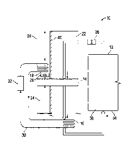
[0029] Referring now to FIG. 1 and FIG. 2, a controlled agricultural
system 10
includes a growing space 12, and an air handling system 13. The air handling
system 13 includes an enthalpy wheel 14, a cooling coil 16 and optionally a
condensing coil 18. The enthalpy wheel 14 is capable of transferring sensible
and
latent heat and is positioned in and rotatable through a recirculating air
duct 22 and
an outside air duct 24 adjacent the recirculating air duct 22. The
recirculating air duct
22 is in fluid connection with the growing space 12 and one or more
recirculating air
fans 26, while the outside air duct 24 is in fluid connection with one or more
outside
air fans 28 positioned to cause outside air to flow countercurrent to
recirculating air.
The cooling coil 16 is positioned within the recirculating air duct 22,
downstream of
and in series with the enthalpy wheel 14. The cooling coil 16 circulates a
heat
CA 02975559 2017-07-31
WO 2017/062476 PCT/US2016/055530
transfer fluid through a heat transfer fluid line 30 to remove heat from the
recirculating air.
[0030] The controlled agricultural system 10 can be operated to control
the
environment within the growing space 12 defined by side walls 34 and an
overhead
wall 36. The side walls 34 and overhead wall 36 can be made of glass as
traditional
greenhouses, with louvers or the like to control the amount of sunlight
entering the
growing space 12. In one embodiment, the side walls 34 and overhead wall 36
are
opaque to sunlight, and artificial light is provided to plants growing in the
growing
space 12 by grow lights 38. The use of grow lights 38 provides additional
flexibility
and energy savings in that the environmental factors can be controlled and
therefore
optimized in terms of plant yield and energy efficiency.
[0031] For example, in some climates it may be advantageous to have
artificial light at night when the temperature of the growing space exterior
is cooler,
and darkness during the day when the temperature of the growing space exterior
is
much hotter, thereby lessening the heat load that must be removed from the
recirculating air. Further, the use of grow lights 38 allows the duration of
light and
darkness to be optimized for both plant yield and energy costs.
[0032] In one embodiment, actual sunlight is completely replaced by
artificial
light. In another embodiment, the light wavelengths, light intensity, and
light duration
can be completely artificial and controlled, thereby eliminating
inefficiencies
associated with weather and seasonal conditions.
[0033] The growing space 12 can be conditioned year round and outside air
can be avoided thereby eliminating problems due to variable seasons, pests,
air
contaminants such as molds, pollen, etc. The constant cooling of the air
within the
growing space 12 can result in significant savings in energy use and resulting
costs.
[0034] In one embodiment, the air in the growing space 12 is circulated
such
that it is not mixed with outside air, thereby minimizing contamination of the
growing
space 12. Recirculating air fans 26 draw air from the growing space 12 through
the
air handling system 13, separated from and in counter current flow to the
outside air
which is pulled from outside the air handling system 13 by the outside air
fans 28
and may be controlled, at least in part, by an outside air damper 39.
[0035] In one embodiment, the enthalpy wheel 14 is positioned in and
rotatable through a bifurcated duct 20. A separating wall 40 bifurcates at
least a
portion of the duct 20, such that the separating wall 40 separates a
recirculating air
6
CA 02975559 2017-07-31
WO 2017/062476 PCT/US2016/055530
portion 22' from an outside air portion 24'. The recirculating air portion 22'
of the
bifurcated duct 20 is sometimes referred to as the recirculating air duct 22.
Likewise,
the outside air portion 24' of the bifurcated duct 20 is sometimes referred to
herein as
the outside air duct 24.
[0036] The enthalpy wheel 14 can be positioned within the bifurcated duct
20,
or within the recirculating air duct 22 and the outside air duct 24, such that
warm
moist air recirculated from the growing space 12 passes though one portion of
the
enthalpy wheel 14 and outside air passes in the opposite direction through the
remaining portion of the enthalpy wheel 14. Brush seals and the like may be
used to
maintain isolation between the recirculating air and the outside air or at
least
minimize contamination of the recirculating air with outside air.
[0037] Energy wheels are a type of air-to-air heat exchanger that can not
only
transfer sensible heat but also latent heat. When both temperature and
moisture are
transferred, the energy wheel is considered an enthalpy wheel. The rotating
energy
wheel heat exchanger is composed of a rotating cylinder filled with an air
permeable
material resulting in a large surface area for the sensible energy transfer.
As the
wheel rotates between the recirculating air portion 22' and the outside air
portion 24'
of the bifurcated duct 20, or through the recirculating air duct 22 adjacent
the outside
air duct 24, the wheel picks up sensible energy (heat) and releases the
sensible
energy into a relatively colder outside air stream. The driving force behind
the
exchange is the difference in temperatures between the opposing air streams
which
is also called the thermal gradient. Nonlimiting examples of suitable material
used
includes polymer, aluminum, and synthetic fiber.
[0038] The moisture or latent energy exchange in enthalpy wheels is
accomplished through the use of desiccants. Desiccants transfer moisture
through
the process of adsorption which is predominately driven by the difference in
the partial pressure of vapor within the opposing air streams. Nonlimiting
examples
of suitable desiccants include silica gel and molecular sieves.
[0039] In some environments, modulating dampers can be used to control
the
flowrate of outside air. Modulating the wheel speed, preheating the air, and
stop/jogging the system offer additional means to control the energy transfer.
Cross-
contamination of the contaminants via the desiccant can also be a concern but
can
be avoided for example through the use of a selective desiccant like a
molecular
sieve.
7
CA 02975559 2017-07-31
WO 2017/062476 PCT/US2016/055530
[0040] In one embodiment, a mixing damper 42 is positioned in the outside
air
duct 24, or the outside air portion 24' of the bifurcated duct 20, downstream
of the
enthalpy wheel 14, and can be used to control the amount of outside air. For
example, one or more industry standard modulating damper(s) can be positioned
in
parallel with the enthalpy wheel 14 and modulated in concert with the outside
air
damper 39 to maintain a desired operation and performance of the enthalpy
wheel
14.
[0041] Temperature and relative humidity measurements can be taken using,
for example, industry standard temperature and humidity sensors. Temperature
and
relative humidity measurements of the outside air stream entering the enthalpy
wheel 14, the recirculating air entering the enthalpy wheel 14, and the
recirculating
air exiting the enthalpy wheel 14 can be used to control the speed of the
outside air
fans 28, the speed of the enthalpy wheel, and control operation of the direct
expansion evaporator cooling coil 16.
[0042] The cooling coil 16 can further cool the recirculating air exiting
the
enthalpy wheel 14. The cooling coil 16 can circulate chilled water, a mixture
of chilled
water and glycol, refrigerant, and the like.
[0043] In one embodiment, chilled water is produced in another portion of
the
facility housing the controlled agricultural system and is utilized to further
cool
recirculating air exiting the enthalpy wheel 14.
[0044] In one embodiment, the cooling coil 16 is a direct expansion
evaporator
cooling coil. A compressor 32 and condensing coil 18 are external to the
recirculating
air duct 22, or the recirculating air portion 22' of the bifurcated duct 20,
and use
outside air to remove heat from the heat transfer fluid.
[0045] Design and operation of evaporator cooling coils are well
understood
by those skilled in the art. Typically condensed and pressurized liquid
refrigerant is
routed through an expansion valve where it undergoes an abrupt reduction in
pressure. That pressure reduction results in flash evaporation of a part of
the liquid
refrigerant, thereby lowering its temperature. The cold refrigerant is then
routed
through the evaporator cooling coil. Air fans blow the recirculating air
across the
evaporator, causing the liquid part of the cold refrigerant mixture to
evaporate as
well, further lowering the temperature. The recirculating air is therefore
cooled by
heat transfer from the direct expansion evaporator cooling coil 16.
[0046] Circulating refrigerant vapor enters the compressor 32 and is
8
CA 02975559 2017-07-31
WO 2017/062476 PCT/US2016/055530
compressed to a higher pressure, resulting in a higher temperature as well.
The hot,
compressed refrigerant vapor is at a temperature and pressure at which it can
be condensed and is routed through the condensing coil 18 located in the
outside air
duct 24, or the outside air portion 24' of the bifurcated duct 20. Outside air
fan(s) 28
causes outside air exiting the enthalpy wheel 14 to flow across the condensing
coil 18. The cooler outside air flowing across the condensing coil 18 causes
the
refrigerant in the coil to condense into a liquid. Thus, in summary, the
circulating
refrigerant removes heat from the recirculating air and the heat is carried
away by
the outside air.
[0047] In
one embodiment, for example when weather or other circumstances
cause the recirculating air to be colder than desired, the refrigeration cycle
can be
reversed and refrigerant is pumped in the opposite direction. The overall
effect is the
opposite, and the recirculating air is heated instead of cooled.
[0048] In
one embodiment, for example when the recirculating air becomes
cooler than desired for recirculating to the growing space 12, one or more
heaters 44
in the recirculating air duct 22, or the recirculating air portion 22' of the
bifurcated
duct 20, can be utilized to control the temperature of the recirculating air
and the
growing space 12. Non-limiting examples of suitable heaters include electrical
resistance heaters, hot water radiators, natural gas furnaces, and the like.
[0049] A
CO2 generator 46 can be used to add CO2 to the recirculating air
duct 22, or the recirculating air portion 22' of the bifurcated duct 20. An
associated
CO2 sensor 48 can sense and read the CO2 level in the recirculating air and
input the
level to a CO2 controller 50. The CO2 generator 46 is controlled by the CO2
controller
50 to maintain the CO2 content at a set point or set range.
[0050] In
one embodiment, the CO2 generator 46 comprises a natural gas
burner located in the outside air duct 24, or the outside air portion 24' of
the
bifurcated duct 20. Locating the natural gas burner in the outside air portion
allows a
majority of the heat related to combustion to exhaust directly outside. Flue
gas from
the natural gas burner is delivered in controlled amounts to the recirculating
air. A
flue gas fan 52 located in the separating wall 40 can be utilized, for example
to meter
the flue gas to the recirculating air portion 22' of the bifurcated duct 20
and thereby
maintain the CO2 content at a set point or set range.
[0051] In
one embodiment, a control louver 54 is also used to purge excess
CO2 from the recirculating air duct 22, or the recirculating air portion 22'
of the
9
CA 02975559 2017-07-31
WO 2017/062476 PCT/US2016/055530
bifurcated duct 20, to maintain the CO2 content at a set point or set range.
[0052] In one embodiment, an industry standard CO2 sensor 48 is installed
in
the recirculating air duct 22, or in the recirculating air portion 22' of the
bifurcated
duct 20. The CO2 sensor 48 feeds back to the CO2 controller 50 within a
central
control system 55 to determine if the natural gas burner should fire and at
what rate
the CO2-containing flue gas should be metered into the air handling system 13
to
meet or maintain a user-defined CO2 set point.
[0053] In one embodiment, the air handling system 13 includes a separate
desiccant wheel 56 for removing moisture from the recirculating air. The
desiccant
wheel 56 is positioned in and rotatable through both the recirculating air
duct 22 and
the outside air duct 24 such that warm moist air recirculated from the growing
space
12 passes though one portion of the desiccant wheel 56 and heated outside air
exiting the condensing coil 18 passes in the opposite direction through the
remaining
portion of the desiccant wheel 56. A separate heat wheel 57 capable of
transferring
sensible heat also positioned in and rotatable through both the recirculating
air duct
and the outside air duct. The heat wheel 57 cools dried recirculating air
exiting the
desiccant wheel 56 and transfers the sensible heat to outside air upstream of
the
desiccant wheel 56.
[0054] As described above for the enthalpy wheel 14, the desiccant wheel
56
is composed of a rotating cylinder filled with an air permeable material
comprising
desiccant. As the desiccant wheel 56 rotates between the recirculating air
duct 22
and the outside air duct 24, it picks up moisture from the moist recirculating
air and
releases it into the drier outside air stream. Desiccants transfer moisture
through the
process of adsorption which is predominately driven by the difference in the
partial
pressure of vapor within the opposing air streams. Suitable desiccants include
silica
gel, and molecular sieves. The outside air with absorbed heat and humidity is
then
discharged from the air handling system 13 and returned to the atmosphere,
[0055] In one embodiment, a recirculating air filter 58 positioned in the
recirculating air duct 22 removes particulate from the recirculating air
before feeding
it back to the growing space 12. Design and operation of air filters are well
understood by those skilled in the art.
[0056] An outside air filter 60 can be positioned in the outside air duct
24 to
remove particulate from the outside air prior to passing it through the
enthalpy wheel
14 or the desiccant wheel 56 and heat wheel 57. Removal of particulate can aid
in
CA 02975559 2017-07-31
WO 2017/062476 PCT/US2016/055530
reducing the maintenance of the wheels.
[0057] The central control system 55 can modulate the fans, wheel(s), and
optionally the compressor to minimize energy consumption. Components of the
system described above can be variable speed. The fans can vary the volume of
air
moved and the wheel speed(s) can vary to maximize efficiency. The mechanical
cooling system including the cooling coil 16 optimally provides only the
cooling
necessary. Control logic for the components can be housed in a common control
cabinet.
[0058] In the embodiment shown in FIG. 2, the air handling system 13 is
constructed adjacent to the growing space 12 with a recirculating air outlet
62
originating from a far side of the growing space 12, and a recirculating air
intake 64
proximate the air handling system 13. While numerous layouts can be used,
separation of the recirculating air outlet and intake 62 and 64, respectively,
improves
efficiency of air replacement in the growing space 12. FIG. 3 through FIG. 5
show
possible equipment layouts in three levels of the air handling system 13.
[0059] A method for treating air within a growing space of a closed
agricultural system includes temperature and moisture control equipment as
described above. Recirculating air from a contained growing space is passed
through an air handling system comprising at least one energy wheel to reduce
the
energy content of the recirculating air. The recirculating air exiting the
energy
wheel(s) is passed across a cooling coil circulating a heat transfer fluid to
further
reduce the heat content of the recirculating air. The recirculating air
passing the
cooling coil is then returned to the contained growing space. Outside air is
passed
through the energy wheel(s) counter-current to and separated from the
recirculating
air.
[0060] In one embodiment, the recirculating air exiting the energy
wheel(s)
can be passed across a direct expansion evaporator cooling coil circulating a
heat
transfer fluid to further reduce the heat content of the recirculating air
before
returning the air to the main portion of the closed structure. The heat
transfer fluid is
cooled by circulating through a compressor and a condensing coil in contact
with the
outside air.
[0061] In one embodiment the energy wheel comprises an enthalpy wheel to
reduce the temperature and the moisture content of the recirculating air. In
another
embodiment, the energy wheels comprise both a desiccant wheel to reduce the
11
moisture content of the recirculating air and a heat wheel to reduce the
temperature
of the recirculating air.
[0062] The method for treating air within a growing space of a closed
agricultural system can additionally include monitoring the CO2 content of air
circulated from the growing space. CO2 is added if the CO2 content is below a
desired value, and a portion of the recirculating air is vented if the CO2
content is
above a level determined to be harmful.
[0063] In the following examples, specific controlled and closed
agricultural
systems are described. However, the present inventive concept(s) is not to be
limited in its application to the specific equipment, plant layout, and
operating
methods. Rather, the Examples are simply provided as one of various
embodiments
and are meant to be exemplary, not exhaustive.
EXAMPLE 1
[0064] In some applications, the humidity level in the closed agricultural
system requires more extensive dehumidification than normal. As shown in FIG.
6, a
desiccant wheel is installed downstream of the recirculation fans and
condensing
coil. The enthalpy wheel is replaced with a heat wheel (sensible heat-only
wheel, no
desiccant). A condensing coil or a natural gas burner acts as regeneration
heat for
the latent heat-only wheel. As the desiccant wheel rotates from one air stream
to the
other it adsorbs the moisture from the recirculation air. That moisture is
then
released to the outside air stream. To aid in that release, regeneration heat
(condensing coil heat and/or optional natural gas burner) is applied to the
air
entering the wheel in the outside air stream. An additional set of temperature
and
relative humidity sensors are installed downstream of the desiccant wheel. The
control system varies the speed of the desiccant wheel to meet the user
defined
relative humidity set point. Similarly, the control system varies the heat
wheel to
meet the user defined temperature set point.
EXAMPLE 2
[0065] The efficiency of the air handling system depends on the outside air
temperature and humidity. When conditions are favorable (cooler dryer
weather), the
system is capable of transferring the heat and humidity of the recirculation
air
through the enthalpy wheel to the cooler and dryer outside air. As indicated
in the
flow diagram shown in FIG. 7, 57 F outside air with 40.7 grains of moisture is
coming
12
Date recue/Date received 2023-05-23
CA 02975559 2017-07-31
WO 2017/062476 PCT/US2016/055530
into the unit and into the enthalpy wheel. The resulting recirculation air
temperature
and grain level off the wheel (60 F/45.1 grains) to provide 100% of the
required
heating and dehumidification.
EXAMPLE 3
[0066] As the outside air temperature and humidity go up, the enthalpy
wheel
can still provide value by "pre-conditioning" the recirculation air before the
cooling
coil. In the flow diagram shown in FIG. 8, 57 F outside air with 60.6 grains
is entering
the air handling unit and the enthalpy wheel. The resulting recirculation air
temperature and grain level off the wheel (60 F/63.2 Grains) is sufficient to
cool the
recirculating air, but it is not sufficient to remove the moisture from the
recirculating
air. As a result the air handling unit control system shall enable the
mechanical
cooling to remove the additional grains of moisture from the recirculation
air, down to
the user defined set point of 48 grains. In order to remove the moisture the
cooling
coil must over cool the air, 50 F. The over cooled air could potentially over
cool the
recirculating air, therefore the air handling unit control system shall enable
the heat
source to heat the recirculating air to the user defined set point.
EXAMPLE 4
[0067] At some point the outside air will be too hot and too wet for the
air
handling system to be able to transfer heat and humidity form the
recirculating air
stream to the outside air stream. In the flow diagram shown in FIG. 9, when
the
control system determines that there is no benefit from the enthalpy wheel,
the wheel
shall stop. At this point the air handling unit is capable of mechanically
cooling all the
recirculating air to meet the user defined set point.
[0068] From the above description, it is clear that the inventive
concept(s)
disclosed herein is well adapted to carry out the objects and to attain the
advantages
mentioned herein as well as those inherent in the inventive concept disclosed
herein.
While exemplary embodiments of the inventive concept disclosed herein have
been
described for purposes of this disclosure, it will be understood that numerous
changes may be made which will readily suggest themselves to those skilled in
the
art and which are accomplished without departing from the scope of the
inventive
concept disclosed herein and defined by the appended claims.
13