Note : Les descriptions sont présentées dans la langue officielle dans laquelle elles ont été soumises.
CA 02977891 2017-08-25
WO 2016/135497 PCT/GB2016/050497
- 1 -
A device for receiving and analysing a sample
BACKGROUND
An impression left by the friction ridges of human skin, such as the skin of a
human finger
contains information regarding the identity of the human. It is widely known
that the
appearance of the impression of the human finger, known as a fingerprint, is
unique to
each human and may be used to confirm the identity of the human. The
appearance of the
impression of the skin of other human body parts may also be unique to each
human and
so may also be used to confirm the identity of the human. Such impressions of
human
skin, when not specific to the skin of the human finger, may be called skin-
prints.
In addition to the appearance of the impression left by human skin, the
impression may
contain chemical species which themselves may be detected in order to obtain
further
information.
For example, when a human intakes a substance (e.g. by ingestion, inhalation
or injection)
the substance may be metabolised by the human body giving rise to secondary
substances
known as metabolites. The presence of a particular metabolite can be
indicative of a
specific intake substance. The intake substance and/or metabolites may be
present in
sweat and, as such, may be left behind in a skin-print, e.g. a fingerprint.
Detection of such
metabolites in a skin-print can be used as a non-invasive method of testing
for recent
lifestyle activity such as (but not limited to) drug use, or compliance with a
pharmaceutical
or therapeutic treatment regime.
Importantly, the taking of a skin-print is much simpler than obtaining other
body fluids such
as blood, saliva and urine, and is more feasible in a wider range of
situations. Not only this
but since the appearance of the skin-print itself provides confirmation of the
identity of the
person providing the skin-print, there can be greater certainty that the
substance or
substances in the skin-print are associated with the individual. This is
because substitution
of a skin-print, particularly a fingerprint, is immediately identifiable from
appearance
whereas substitution of, for example, urine, is not immediately identifiable
from
appearance. As such, testing for one or more substances in a skin-print
provides a direct
84059843
- 2 -
link between the one or more substances and the identity of the human
providing the
skin-print.
It is important, therefore, that a substrate on which a skin-print is
collected cannot be
.. contaminated (either innocently or maliciously) before or after the
impression of the skin
is taken. The substrate must be accessible only for the short period during
which the
skin-print is taken.
It is also desirable for metabolite detection not only to be reliable but also
to be simple,
efficient and user-friendly. Furthermore, since a volume of metabolite that,
if present,
might be expected in a fingerprint is likely to be of the order of
microliters, it is desirable
to maximise the proportion of the skin-print that is analysed in order to
maximise
accuracy of the test.
STATEMENTS OF INVENTION
According to an aspect of the present disclosure, there is provided a device
for receiving
and analysing a sample, wherein the analysing involves use of a solution, the
device
comprising:
a sample receiving portion for receiving a sample to be analysed; a solution
capsule containing a specific volume of solution, the solution capsule having
a sealed
configuration in which the solution capsule is sealed and a release
configuration in which
the solution contained in the solution capsule is released via a flow path
that provides
fluid communication between the solution capsule and the sample receiving
portion; and
a bistable release mechanism comprising an actuator wherein the bistable
release
mechanism releases only in the event that a force applied to the actuator
reaches a
threshold force and wherein actuation of the actuator results in one-way
conversion of
the solution capsule from the sealed configuration into the release
configuration such that
all of the specific volume of solution is released.
Date Recue/Date Received 2022-04-08
84059843
- 2a -
In another aspect, there is provided a device for receiving an analysing a
sample,
wherein the analysing involves use of a solution, the device comprising:
a sample receiving portion for receiving a sample to be analysed;
a solution capsule having a sealed configuration in which the solution capsule
is
sealed and a release configuration in which contents of the solution capsule
are released
via a flow path that provides fluid communication between the solution capsule
and the
sample receiving portion; and
a bistable release mechanism comprising an actuator wherein the bistable
release
mechanism releases only in the event that a force applied to the actuator
reaches a
threshold force and wherein actuation of the actuator results in one-way
conversion of
the solution capsule from the sealed configuration into the release
configuration.
In this way, a skin-print, most likely a fingerprint, may be securely received
and reliably
analysed for presence of one or more chemical species.
In a further aspect, there is provided a device for receiving and analysing a
sample,
wherein the analysing involves use of a solution, the device comprising:
a first sample receiving portion comprising a wicking material for receiving a
sample to be analysed using the solution; and
Date Recue/Date Received 2022-04-08
CA 02977891 2017-08-25
WO 2016/135497 PCT/GB2016/050497
- 3 -
a second sample receiving portion comprising a non-porous substrate.
In this way, the device may be used to collect two skin-prints, most likely
two fingerprints,
one for chemical analysis and another for optical analysis.
BRIEF DESCRIPTION OF THE DRAWINGS
Specific embodiments of the invention will now be described, by way of example
only, with
reference to the accompanying drawings in which:
Figure 1 shows a perspective view of device in accordance with a first
embodiment of
the invention;
Figure 2 shows an exploded view of the device of Figure 1;
Figure 3 shows a perspective view of the device of Figure 1 with some of the
components removed and others part cut away so as to show internal features;
Figure 4 shows a perspective view of a lateral flow substrate that is present
within the
device of Figure 1;
Figure 5 shows a solution capsule of the device of Figure 1;
Figure 6 shows the solution capsule of Figure 5 with a surface removed,
revealing
internal features;
Figure 7 shows a part of the capsule of Figure 5 relative to other components
of the
device;
Figure 8 shows the device of Figure 1 with a capsule removed;
Figure 9 shows the capsule assembly of the device of Figure 1 with the capsule
in an
initial configuration;
CA 02977891 2017-08-25
WO 2016/135497 PCT/GB2016/050497
- 4 -
Figure 10 shows the capsule assembly of the device of Figure 1 with the
capsule in a
subsequent configuration
Figure 11 shows a cross sectional view of the capsule assembly with the
capsule in the
initial configuration;
Figure 12 shows a view of parts of the device of Figure 1 with the capsule in
the initial
configuration;
Figure 13 shows an enlarged view of parts of the device of Figure 1, centred
on a pair
of piercers which are a constituent part of the device;
Figure 14 shows a cross-sectional view of the pair of piercers;
Figure 15 shows a variation on the device of Figure 1 having a tear-off strip
in situ;
Figure 16 shows the device of Figure 1 with the shutter as it appears in both
a first and
a third configuration and with the solution capsule in an initial
configuration;
Figure 17 shows the device of Figure 1 with the shutter in a third
configuration and the
solution capsule in a subsequent configuration;
Figure 18 shows a part of the device of Figure 1 from an internal perspective;
Figure 19 shows a perspective view of a device in accordance with a second
embodiment of the invention;
Figure 20 shows a perspective view of a substrate in accordance with the third
embodiment of the disclosure; and
Figure 21 shows a perspective view of a lower portion of the housing in
accordance
with a third embodiment of the disclosure.
= CA 02977891 2017-08-25
84059843
- 5 -
SPECIFIC DESCRIPTION
First embodiment
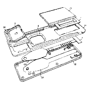
In accordance with a first embodiment, as shown in Figure 1, there is a device
1 for receiving
and analysing a sample. The first embodiment is shown in an exploded view in
Figure 2.
The device comprises a housing 2 and a sample receiving material in the form
of a
substrate 4 that is located within the housing 2. The housing 2 comprises a
body 3 having an
upper portion 31 and a lower portion 32. The lower portion 32 comprises an
indentation 33
that reflects a shape of the substrate 4. The housing 2 also comprises a
solution capsule
assembly 50 comprising a solution capsule 5. The housing 2 further comprises a
sample
window 6 that bounds a skin-print receiving region 42 of the substrate 4. The
dimensions of
the sample window 6 may be configured to allow receipt of at least a part of
an area of a
skin-print, such as a fingerprint. The housing 2 further comprises a result
window 7 and a
shutter 10 that is slidable relative to the body 3.
The substrate 4 is of a porous, wicking material, such as Fusion 51-m. The
frangible enclosing
member 54 of the solution capsule 5 is of a laminar material comprising a
layer of
polypropylene and a layer of aluminium. The solution capsule assembly 50
(except for the
frangible enclosing member 54) is of polypropylene. The remaining components
of the
housing 2 are of high density polystyrene (HDPS).
The laminar material comprising a layer of polypropylene and a layer of
aluminium is selected
such that it pierces cleanly and predictably.
The device 1 of Figure 1 is shown again in Figure 3 with the upper body
portion 32 and the
solution capsule assembly 50 shown in cross-section and with the shutter 10
removed
altogether. This renders some of the internal features more visible than in
Figure 1.
The substrate 4 is mounted in the housing 2 and is in a fixed position
relative to the
housing 2. The housing 2 is intended to protect the substrate 4. The housing
may be
opaque in order to protect substances that are susceptible to photodegradation
which may
be present on the substrate 4.
CA 02977891 2017-08-25
WO 2016/135497 PCT/GB2016/050497
- 6 -
The substrate 4, shown in isolation in Figure 4, comprises the skin-print
receiving region
42, a solution-receiving region 43 and an analysis region 44. The analysis
region 44
comprises a result line 45 and a control line 46, both of which are located
within the result
window 7. The analysis region 44 further comprises an absorbent solution sink
47,
downstream of the result line 45 and control line 46, which simply acts to
soak up fluid that
has already passed through the previous parts of the lateral flow test. The
solution-
receiving region 43 of the substrate 4 may comprise an aperture 435.
.. The solution receiving region 43 of the substrate 4 is of variable width.
In the vicinity of the
aperture 435 the solution receiving region 43 is at its narrowest. With
distance towards the
skin-print receiving region 42, the width of the solution-receiving region 43
increases.
The solution-receiving region 43 may have a portion of constant width and a
portion of
narrowing width towards the analysis region 44. The analysis region 44 may be
of constant
width. The width of the absorbent sink 47 may again be wider.
The shutter 10 comprises an inside 10a that faces inwardly towards the
substrate and an
outside 10b which faces outwardly. The shutter 10 may further comprise a
gripping feature
(not shown) on the outside 10b of the shutter to assist in sliding of the
shutter 10.
The shutter 10 is movable with respect to the body 3 from a first position, to
a second
position and into a third position.
In the first position (shown in Figure 16), the sample window 6 is covered by
the shutter 10
and the result window 7 is not covered by the shutter 10. In the second
position (shown in
Figure 1), the sample window 6 is not covered by the shutter 10 and the result
window 7 is
covered by the shutter 10. In the third position (which appears the same as
the first
position, shown in Figure 16), the sample window 6 is again covered by the
shutter 10 and
the result window 7 is not covered by the shutter 10.
Viewed from the outside, therefore, in the case of the illustrated embodiment,
it may be that
the first and third positions appear identical. However, the third position is
different from
the first position in that, once in the third position, the shutter cannot
again be moved into
the second position.
CA 02977891 2017-08-25
WO 2016/135497 PCT/GB2016/050497
- 7 -
In this way, if a user receives the device 1 of the first embodiment in a
configuration where
the sample window 6 is covered by the shutter 10, the user will attempt to
move the shutter
into the second position. If this is not possible, this is because the shutter
10 is already
5 in the third position. Accordingly, the device 1 is not usable since the
skin-print receiving
region 42 bounded by the sample window 6 is inaccessible. This prevents reuse
of an
already-used device 1 or use of a device 1 that may have been subject to
tampering (and
hence possible contamination that may influence a result to be obtained using
the device).
10 On the other hand, if it is possible for a user to move the shutter 10
into the second
position, this indicates to the user that the device 1 has not been used
previously and that
the skin-print receiving region 42 bounded by the sample window 6 has not
previously been
exposed.
The third position being different from the first position may be achieved by
one or more
internal snap-fit features that prevent the shutter from moving back to the
first position
following the second position and also retain the shutter in the third
position.
The sample window 6 comprises an aperture in the body 3 of the housing 2, such
that the
sample window 6 bounds the skin-print receiving region 42. The sample window 6
and
hence the skin-print receiving region 42 are only accessible when the shutter
10 is in the
second position.
At least a part of the analysis region 44 of the substrate 4 is bounded by the
result window
7.
The solution capsule assembly 50 (see Figures 9 and 10) comprises a capsule
surround
56, a hinge 57 and a solution capsule 5. The capsule surround 56 is attached
to the upper
portion 31 of the base 3 via locating pins (680) on the underside of the
capsule surround
(see Figure 18) that are received into corresponding locating sockets (380) in
the base 3
(see Figure 18). The solution capsule 5 is connected to the capsule surround
56 via the
hinge 57. The capsule surround 56 comprises a pair of ramped guard portions
58, 59 that
sit on opposite sides of the capsule surround 56. The ramped guard portions
58, 59 act to
prevent access to the sides of the capsule 5 and also to prevent movement of
the capsule
CA 02977891 2017-08-25
WO 2016/135497 PCT/GB2016/050497
-8-
with respect to the capsule surround 56 by an object that is larger than the
distance
between the ramped guard portions 58, 59.
The capsule 5, shown in isolation in Figure 5, comprises a substantially rigid
cup portion 51
5 having sidewalls 521, 522, 523, 524 and a substantially planar base 53.
Together, the
sidewalls 521, 522, 523, 524 and planar base 53 provide a cup-shaped reservoir
with an
open end substantially opposite the planar base 53. The solution capsule 5
further
comprises a frangible enclosing member 54 that is fastened to or proximate to
a perimeter
of the open end of the cup portion 51 so as to seal the open end. In this way,
a solution in
the cup portion 51 can be sealed within the solution capsule 5 once the
frangible enclosing
member 54 seals the open end of the cup portion 51. Alternatively, the
solution may be
injected into the capsule 5 after the frangible enclosing member 54 has
already sealed the
open end of the cup portion 51.
With the exception of the frangible enclosing member 54, the solution capsule
assembly 50
(that comprises the capsule surround 56, hinge 57 and solution capsule 5) may
be
moulded of a single piece.
Figure 6 shows the rigid cup portion 51 of the solution capsule 5. The
sidewalls of the rigid
cup portion 51 comprise first, second, third and fourth sidewalls, 521, 522,
523, 524. The
first and second sidewalls 521, 522 are substantially of equal length and are
mutually
parallel. The third and fourth sidewalls 523, 524 are substantially of equal
length and are
mutually parallel. The first and second sidewalls 521, 522 are longer than the
third and
fourth sidewalls 523, 524. The first and second sidewalls 521, 522 are
perpendicular to the
third and fourth sidewalls 523, 524. The hinge 57 is adjacent the first
sidewall 521.
The open end of the sidewalls comprises a sealing surface 525 that is largely
perpendicular
to a major surface of each of the respective sidewalls 521, 522, 523, 524. The
frangible
enclosing member 54 (not shown) is fastened to the sealing surface 525 by a
fastening that
comprises a continuous weld seal. The sealing surface, prior to receiving the
frangible
enclosing member 54, comprises an upstanding portion 528 having a triangular
cross
section. The upstanding portion 528 is configured to melt into the frangible
enclosing
member 54 during a process in which the frangible enclosing member 54 is
welded to the
sealing surface 525.
CA 02977891 2017-08-25
WO 2016/135497 PCT/GB2016/050497
- 9 -
The polypropylene layer of the frangible enclosing member 54 is orientated
adjacent the
polypropylene upstanding portion 528 of the polypropylene capsule assembly 50
in order
that the two facing polypropylene surfaces melt together under a heat welding
process.
The second sidewall 522 comprises a pair of projecting elements 526, 527 that
project
inwardly from the second sidewall 522 that is opposite the hinge 57. The pair
of projecting
elements 526, 527 is substantially mutually parallel.
The housing 2 comprises a recess 60 (see Figure 8) that comprises an upper
portion that is
situated in the solution capsule assembly 50 and a lower portion that is
situated in the
upper portion 31 of the body 3.
The device 1 is shown in Figure 8 with the capsule 5 of the solution capsule
assembly 50
removed to show more clearly the recess 60 in which the solution capsule sits.
The recess 60 comprises sidewalls 621, 622, 623, 624 that are dimensioned
slightly larger
than the sidewalls 521, 522, 523, 524 of the cup portion 51 of the solution
capsule 5. The
sidewalls 621, 622, 623, 624 of the recess 60 comprise first, second, third
and fourth
sidewalls, 621, 622, 623, 624. The first and second sidewalls 621, 622 are
substantially of
equal length and are mutually parallel. The third and fourth sidewalls 623,
624 are
substantially of equal length and are mutually parallel. The first and second
sidewalls 621,
622 are longer than the third and fourth sidewalls 623, 624. The first and
second sidewalls
521, 522 are perpendicular to the third and fourth sidewalls 523, 524. The
first, second,
third and fourth sidewalls 621, 622, 623, 624 of the recess 60 are,
respectively, adjacent
and parallel to the first, second, third and fourth sidewalls, 521, 522, 523,
524 of the
capsule 5. The hinge 57 is adjacent the first sidewall 621.
The recess 60 also comprises a base 3a that is formed of a surface of the body
3, in
particular an internal surface of the lower portion 32 of the body 3.
The depth of the sidewalls 621, 622, 623, 624 of the recess 60 is similar to
the depth of the
sidewalls 521, 522, 523, 524 of the cup portion 51. Since the solution capsule
assembly 50
is fixedly attached to the upper portion 31 of the body 3, the solution
capsule 5 is pivotally
mounted to the body 3 via the hinge 57 and the capsule surround 56. The
orientation of
the solution capsule 5 is such that the frangible enclosing member 54 faces
the base 3a.
CA 02977891 2017-08-25
WO 2016/135497 PCT/GB2016/050497
- 10 -
At a second sidewall 622 of the recess 60, opposite the first sidewall 621 of
the recess 60,
the recess 60 comprises a protrusion 66 that protrudes from an interior of the
second
sidewall 622. The protrusion 66 (see Figure 12) extends from the second
sidewall 622 of
the recess 60 towards an interior of the recess 60. A dimension between the
first sidewall
621 of the recess 60 and an inmost surface of the protrusion 66 is slightly
smaller than a
corresponding external dimension of the solution capsule 5 (e.g. the distance
between the
first sidewall 521 of the solution capsule 5 and the second sidewall 522 of
the solution
capsule 5).
At a lower end of the third and fourth sidewalls 623, 624 of the recess 60 is
a protrusion
629a, 629b.
In an initial configuration of the solution capsule 5 (see, for example,
Figures 9 and 11), a
.. first end 58 of the solution capsule 5 adjacent the first sidewall 521 of
the solution capsule
5 substantially does not protrude above the first sidewall 621 of the recess
60 at a first end
68 of the recess 60. Also in the initial configuration, a second end 59 of the
solution
capsule 5 adjacent the second sidewall 522 of the solution capsule 5 sits
substantially
proud of the second sidewall 621 of the recess 60 at a second end 69 of the
recess 60.
The second end 59 of the solution capsule 5 sits proud of the second sidewall
622 of the
recess 60 since the protrusion 66 restricts movement of the second end of the
solution
capsule 5 into the second end of the recess 69. As such, though the frangible
enclosing
member 54 faces the base 3a, the frangible enclosing member 54 is not parallel
with the
base 3a. Rather, the frangible enclosing member 54 is inclined from the first
end of the
capsule to the second end of the solution capsule 5.
The location and dimension of the protrusion 66 are configured to allow the
second end 59
of the solution capsule 5 to move into the second end 69 of the recess 60 (by
rotation
about the hinge 57) only once a specified threshold force has been applied to
the second
end 59 of the substantially planar base 53 of the solution capsule 5 in order
to overcome
resistance to such movement that is provided by the protrusion 66. This may be
known in
the art as a slip latch. The threshold force may, for example, be 10 Newtons.
A
subsequent configuration of the solution capsule 5 (that is, subsequent to the
initial
configuration of the solution capsule 5) is achieved once the specified
threshold force has
been applied such that the resistance to movement has been overcome and so the
second
CA 02977891 2017-08-25
WO 2016/135497 PCT/GB2016/050497
-11 -
end 59 of the solution capsule 5 moves into the recess 60. In this subsequent
configuration, shown in Figure 10, the frangible enclosing member 54 may be
substantially
parallel to the base 3a.
As evident in Figure 6, the solution capsule 5 comprises a pair of ears 529a,
529b. The
ears 529a and 529b extend outwards from the third and fourth walls 523, 524 of
the
capsule 5 such that a dimension from an outer end of one ear 529a to an outer
end of the
other ear 529b is wider than the width of the recess 60. The ears 529a, 529b
of the
solution capsule 5 are located such as to be received within the detents 629a,
629b,
respectively, of the recess 60, as shown in Figure 18. Accordingly, the ears
529a, 529b
prevent the solution capsule 5 from being lifted relative to the capsule
surround 56.
The body 3 further comprises a pair of piercers 91, 92 (see Figures 13 and
14). In the first
embodiment, the piercers are spaced apart by a distance of approximately 1 mm.
Each of
the two piercers 91, 92 comprises a proximal end 91a, 92a and a distal end
91b, 92b. The
proximal end 91a, 92a of each piercer is fastened to, or otherwise projects
from, the base
3a within recess 60. The proximal end 91a, 92a of each piercer may be
substantially
central relative to the sidewalls 621, 622, 623, 624 of the recess 60. The
distal end 91b,
92b of each piercer sits proud of the base 3a within recess 60. The distal end
91b, 92b of
each piercer comprises a piercing feature or piercing profile such as an acute
shape.
The location of the piercers 91, 92 is such that, in the initial configuration
of the solution
capsule 5, the piercers are distant from the frangible enclosing member 54 of
the capsule 5
and such that, in the subsequent configuration of the solution capsule 5, the
piercers
project through (thereby piercing) the frangible enclosing member 54 of the
capsule 5.
The substrate 4 is parallel to the base 3a of the body 3. The aperture 435 in
the solution-
receiving region 43 of the substrate 4 surrounds the pair of piercers 91, 92.
Use of the device will be described in detail below. However, features of the
piercers 91,
92 are dictated, in part, by their required functionality. Accordingly, the
following paragraph
describes some aspects of the device 1 in use in order to illustrate features
of the piercers
91, 92. These aspects of the piercers are illustrated in Figure 14.
CA 02977891 2017-08-25
WO 2016/135497 PCT/GB2016/050497
- 12 -
A distance between the piercers 91, 92 is configured such that, when the
buffer capsule 5
enters the subsequent configuration (such that the frangible enclosing member
54 is
pierced in the regions of each of the two piercers 91, 92), solution present
in the buffer
capsule 5 is drawn between the two piercers 91, 92 and, by virtue of a surface
tension
present on the solution between the two piercers 91, 92, a capillary pull
action results
which draws a drop of solution out of the buffer capsule 5 to be absorbed by
the solution-
receiving region 43 of the substrate 4 that surrounds the pair of piercers 91,
92.
Immediately after the drop of solution is released from between the two
piercers 91, 92,
there is an absence of solution between the two piercers which allows the
opportunity for
ambient air to enter the buffer capsule 5 in order to equalise pressure inside
and outside
the buffer capsule 5. Once the pressure is equalised, a further drop of
solution is drawn
between the two piercers 91, 92 and the same process is repeated.
The pair of piercers 91, 92 is located relative to the solution capsule 5 such
that the pair of
__ piercers 91, 92 is aligned with an area of the frangible enclosing member
54 that is within
an area between the pair of projecting elements 526, 527 that project inwardly
of the
second sidewall 522. (This relationship is clear from Figure 7, in which
various
components, including the frangible enclosing member 54, are removed for
clarity.)
Consequently, when, in use (as described further below), the piercers 91, 92
pierce the
frangible enclosing member 54, the strain force on the weld is reduced which
prevents the
weld from failing as a consequence of transverse forces.
Furthermore, the pair of piercers 91, 92 is located relative to the solution
capsule 5 such
that the location of the flow path out of the solution capsule 5 once the
piercing occurs is
precisely known.
Since the substrate 4 comprises a wicking material that draws (or wicks)
solution, solution
received on the solution-receiving region 43 is drawn from that region towards
the skin-print
receiving region 42 and onward to the analysis region 44.
The substrate 4 (see Figure 4) may be configured for a lateral flow analysis,
which is
known in the art. The following is a brief explanation of the lateral flow
method in the
context of the present embodiment. Variations on this lateral flow technique
fall within the
scope of the claimed invention.
CA 02977891 2017-08-25
WO 2016/135497 PCT/GB2016/050497
- 13 -
Lateral flow immunoassays are simple tests for rapid detection of the presence
or absence
of a target analyte in a sample for home testing, point of care testing, or
laboratory
applications. Lateral flow devices preferably utilise a solid support through
which a mobile
phase (e.g., a buffer solution) can flow through by capillary action to a
reaction matrix
where a detectable signal, such as colour changes or colour differences at a
test site, may
be generated to indicate the presence or absence of the target analyte. As
used herein,
the term "capillary action" refers to the process by which a molecule is drawn
across the
lateral test device due to such properties as surface tension and attraction
between
molecules.
The lateral flow device as described herein is for use in an immunoassay i.e.
a method for
analysing a sample comprising from 0.1 pg to 1 pg of analyte. The immunoassay
comprises a competitive binding assay, where any labelled probe (e.g.
antibody) not bound
to analyte provides an identifiable signal in the test site whilst any
labelled probe bound to
analyte, e.g. in the form of an immunocomplex, passes through the test site
and does not
provide an identifiable signal in the test site. As the number of analyte
molecules present
in the sample increases, the amount of unbound labelled probe passing through
the test
site decreases. Thus the higher the level of analyte in the sample, the weaker
the
identifiable signal at the test site will be. Such a device/method allows
qualitative tests to
be undertaken, i.e. whether or not the sample contains an analyte of interest.
Such a
device/method also may also allow quantitative tests to be undertaken by
measuring the
intensity of the signal at the test site, whereby the higher the intensity of
the signal, the
lower the amount of analyte in the sample.
In the context of the first embodiment, movement of the solution capsule 5
into the
subsequent configuration results in solution being released in a controlled
fashion onto the
solution receiving region 43. Solution is drawn (wicked) down the substrate
towards the
skin-print receiving region 42. The solution is selected to dissolve chemical
species that
may be present in the skin-print receiving region 42, such as an analyte of
interest that may
be present in a skin-print on the skin-print receiving region 42. The solution
(which may or
may not now include the analyte of interest) continues to be drawn down the
substrate 4
into the analysis region 44. The analysis region 44 of the substrate 4 may
have a reduced
width by comparison with the skin-print receiving region 42, to assist in
concentrating the
solution into a smaller area. The analysis region 44 comprises a competitive
binding assay
having a label. If present, the analyte of interest will bind to the labelled
assay. The label
CA 02977891 2017-08-25
WO 2016/135497 PCT/GB2016/050497
- 14 -
may comprise a fluorescent tag. The analysis region 44 further comprises the
result line 45
that is located within the result window 7. The result line 45 comprises a
further molecule,
a protein-analyte conjugate, which is fixed in position (immobilised) on the
substrate 4. The
protein-analyte conjugate is chosen to bind with the assay in the event that
the assay has
not already been bound to the analyte of interest. Hence, if the analyte of
interest is
present, all available assay binding sites are occupied, the further molecule
cannot bind
with the assay and so the assay passes through. If, however, the analyte of
interest is
absent, the further molecule binds with the assay which is then fixed in
position on the
substrate. Since the assay is labelled, once sufficient assay is fixed in
position, the label
becomes apparent through, for example, a change in colour. That is to say, the
result line
45 appears to change colour. The label may be fluorescent.
In addition to the result line 45, there may also be a control line 46. The
control line 46 may
be configured to capture a control assay that is present in the buffer
solution. The purpose
of the control line 46 may be to show that the reaction conditions were as
expected even
when the result line 45 does not change colour (indicating that an
insufficient presence of
the analyte of interest).
It will be apparent that, for an appropriate sensitivity to a particular
analyte, a specific
volume of the solution used to dissolve the skin-print must be used. The
device 1 may be
supplied with the specific volume of solution in the solution capsule 5.
Moreover, the
solution capsule 5 and solution release mechanism need to be configured in
order to
ensure that all of the specific volume of solution is released and that none
of the specific
volume of solution remains in the solution capsule 5 at the conclusion of the
test.
Furthermore, the solution release mechanism needs to be configured in such a
way as to
release the solution in a predictable flow rate, in order to maximise
efficiency of bonding.
The device of the illustrated embodiment is approximately 92 mm in length, 32
mm in width
and 6 mm in thickness, increasing to 9.5 mm in thickness in the region of the
solution
capsule assembly. The sample window 6 is approximately 15 mm x 15 mm. Other
dimensions are possible and fall within the scope of the appended claims.
First embodiment in use
The following section describes the first embodiment of the device, in use.
CA 02977891 2017-08-25
WO 2016/135497 PCT/GB2016/050497
- 15 -
The device 1 is supplied with the shutter 10 in the first position and the
solution capsule 5
in the initial configuration (as shown in Figure 16). The solution capsule 5
is supplied with
a precise volume of a solution. This may be chosen to dissolve effectively one
or more
components of what would be expected to be present in a human finger print. It
may, more
specifically, be selected to dissolve effectively at least the chemical
species of interest
which the test is configured to detect.
When the device is to be used to perform a test, the shutter 10 is moved from
the first
position to the second position (as shown in Figure 1). In doing this, the
sample window 6
that bounds the skin-print receiving region 42 is revealed, having previously
been hidden
by the shutter. A user applies a skin-print (most likely a fingerprint) to the
skin-print
receiving region 42, perhaps under the guidance of another party.
Once the skin-print has been applied to the skin-print receiving region 42,
the shutter 10 is
moved from the second position to the third position (such that the device
again appears
the same as shown in Figure 16). In the third position, the sample window 6
and the skin-
print receiving region 42 are again hidden by the shutter 10. Instead, the
result window 7 is
revealed. Also, once the shutter is in the third position, the shutter cannot
be moved back
to the second position.
Subsequently, the user or another party applies a force to the planar base 53
of the
solution capsule 5. If the force is above the threshold force (for example, 10
Newtons), the
solution capsule 5 moves from its initial configuration, in which the solution
is sealed within
the solution capsule 5, into its subsequent configuration, in which the
frangible enclosing
member 54 is pierced by the pair of piercers 91, 92 to produce a pair of
pierced holes in the
frangible enclosing member. This is shown in Figure 17.
As mentioned above, the distance between the piercers 91, 92 is configured
such that,
when the buffer capsule 5 enters the subsequent configuration, solution
present in the
buffer capsule 5 is drawn between the two piercers 91, 92. A surface tension
present on
the solution between the two piercers 91, 92 initiates a capillary pull action
that draws a
drop of solution out of the buffer capsule 5 to be absorbed by the solution-
receiving region
43 of the substrate 4 that surrounds the pair of piercers 91, 92. Immediately
after the drop
of solution is released from between the two piercers 91, 92, there is an
absence of
CA 02977891 2017-08-25
WO 2016/135497 PCT/GB2016/050497
- 16 -
solution between the two piercers which allows the opportunity for ambient air
to enter the
buffer capsule 5 in order to equalise pressure inside and outside the buffer
capsule 5.
Once the pressure is equalised, a further drop of solution is drawn between
the two
piercers 91, 92 and the same process is repeated. In this way, the release of
solution onto
the solution-receiving region 43 of the substrate 4 is controlled, albeit
passively, at a
constant rate.
The rate of flow of solution out of the solution capsule is influenced by,
among other things,
the width between the piercers 91, 92 and the viscosity of the solution being
dispensed
from the solution capsule 5. This is in part because the flow path is bounded
by the two
piercers 91, 92. In the first embodiment, the piercers are spaced apart a
distance of 1 mm.
In the event that the 300 I of aqueous solution having the following
properties: 10%
methanol; 10 mM phosphate buffer; 0.05% Tween 80; pH7.4, is dispensed, it
would be
expected to exit the solution capsule at a constant rate over a period of
approximately 1 to
2 minutes.
After leaving the solution capsule 5, solution is drawn down the substrate
from the solution-
receiving region 43 to the skin-print receiving region 42. Since the piercers
are only
separated by a 1 mm the location where the solution is deposited out of the
solution
capsule is precise. In this way, variation is reduced and results are more
consistent. The
widening of the substrate 4 with distance away from the source of the solution
acts to draw
the solution towards the skin-print receiving region 42 since the skin-print
receiving region
42 has a greater capacity to absorb solution by virtue of being wider. The
solution acts to
dissolve chemical species that may be present in the skin-print off the skin-
print receiving
region 42. The solution, together with the dissolved chemical species, is
drawn further
down the substrate 4. Where the substrate becomes thinner, between the skin-
print
receiving region 42 and the analysis region 44, the solution becomes
concentrated into a
smaller area.
By configuring the solution capsule to dispense solution at approximately the
rate
described above, there is a relatively high efficiency in dissolving the
chemicals species of
an average-sized human fingerprint that has been deposited on the skin-print
receiving
region and carrying those chemicals species towards the analysis region 44.
CA 02977891 2017-08-25
WO 2016/135497 PCT/GB2016/050497
- 17 -
If the analyte of interest is present in the skin-print (e.g. fingerprint) and
is dissolved and
carried with the solution to the analysis region 44, the analyte will bind
with the labelled
competitive binding assay that is present in the analysis region 44 downstream
of the skin-
print receiving region 42 but upstream of the result line 45. The labelled
competitive
binding assay is drawn further down the substrate 4 as the solution is drawn
down.
If the labelled competitive binding assay has bound to the analyte (because
the analyte is
present), when the solution reaches the result line 45 its binding sites will
be occupied and
it will not bind to the protein-analyte conjugate that is immobilised on the
result line 45.
Hence, the labelled conjugate will pass through the result line (and the
control line) towards
the absorbent sink 47.
If, on the other hand, the labelled competitive binding assay has not bound to
analyte
(because the analyte is not present), when the solution reaches the result
line 45 its
binding sites will be available to bind with the protein-analyte conjugate
that is immobilised
on the result line 45. Hence, the labelled conjugate will become visible at
the result line.
Whatever happens at the result line, a control assay (also labelled) that is
present in the
buffer solution will bind with an immobilised conjugate at the control line
46. Hence, the
labelled control assay will become visible at the control line 46. This
provides a user with
confidence that the test has been successful, whether the result line 45 shows
a positive or
negative result.
Second embodiment
A second embodiment of the invention is illustrated in Figure 19. This
embodiment is
largely similar to the first embodiment and also comprises a second skin-print
receiving
region 41b. The second skin-print receiving region 41b may be located on a
second
substrate that may be independent of the lateral flow substrate 4. For
example, the second
substrate may be of glass.
The second skin-print receiving region 41b may be bounded by a second sample
window
6b adjacent the sample window 6. Unlike the first skin-print receiving region
which,
because of the lateral flow technique requires a wicking substrate, the second
skin-print
receiving region 41b may comprise a non-porous substrate.
CA 02977891 2017-08-25
WO 2016/135497 PCT/GB2016/050497
- 18 -
Both sample windows 6, 6b and both skin-print receiving regions 41, 41b may be
concealed by the shutter 10 in the first position of the shutter 10, revealed
in the second
position of the shutter 10 and concealed again by the shutter 10 in the third
position of the
shutter 10.
It may be the case that the second embodiment comprises further features that
allow the
shutter 10 to be released from the third position only on triggering of a
tamper evident
feature. Release from the third position in such circumstances may allow the
shutter to
move back to the second position, thus revealing the second sample window 6b
and
second skin-print receiving region 41b for a second time. This may allow an
authorised
user to analyse an image of the skin-print on the second skin-print receiving
region 41b to
confirm identity of the skin-print on the second skin-print receiving region
41b.
Other aspects of the second embodiment, where not explicitly described and/or
illustrated
as differing from the first embodiment, may be identical to those of the first
embodiment.
Second embodiment in use
Use of the second embodiment is largely the same as that of the first
embodiment, except
that when the shutter is in the second position, a user is required not only
to place a skin-
print in the first skin-print receiving region 41 bounded by the sample window
6 but also to
place a skin-print in the second skin-print receiving region 41b bounded by
the second
sample window 6b.
Further, analysis of the skin-print using the lateral flow technique may be
conducted as per
the first embodiment and, in addition, analysis as to the identity of the skin-
print may be
obtained separately by comparing the skin-print in the second skin-print
receiving region
41b with, for example, a skin-print in a database.
Use of the second embodiment may involve a separate analysis of the second
skin-print
present in the second skin-print receiving region 41b. This separate analysis
may involve
triggering a tamper evident feature to release the shutter 10 from the third
position. The
separate analysis may comprise photographing the second skin-print in order to
compare a
CA 02977891 2017-08-25
WO 2016/135497 PCT/GB2016/050497
- 19 -
photographed image with images in a database, for example. This analysis may
take place
at a different time and location from the lateral flow analysis, if required.
Third embodiment
Figure 21 shows the lower portion 32' of the body 3 of the housing 2 of a
third embodiment
of the disclosure. A comparison of the lower portion 32' of the third
embodiment may be
made with the lower portion 32 of the first embodiment by comparing Figure 21
with the
lower-most component shown in Figure 2. Figure 20 shows a substrate 4' for use
in the
third embodiment. This compares with the substrate 4 of the first embodiment
as illustrated
in Figure 4.
There are three main differences between the lower portion 32' of the third
embodiment
and the lower portion 32 of the first embodiment.
First, in the third embodiment, the spatial relationship of the piercers 91'
92' is different
from that of the first embodiment. In particular, the piercers 91', 92' are
spaced further
apart in the third embodiment than are the piercers 91, 92 of the first
embodiment.
Preferably, the piercers are spaced apart by a distance of approximately 9 mm.
Secondly, the indentation 33' of the second embodiment has a different shape
than that of
the indentation 33 of the first embodiment. As in the first embodiment, the
indentation 33'
may reflect the shape of the substrate 4'. Accordingly, the substrate 4'
(Figure 20) of the
third embodiment may have a different shape from the substrate 4 of the first
embodiment.
Thirdly, the lower portion 32' of the third embodiment comprises locator
components 34'
that act to locate and/or retain the substrate 4 within the indentation 33' of
the lower portion
32'.
Like the substrate 4 of the first embodiment, the substrate 4' of the third
embodiment has a
solution-receiving region 43' having a portion of constant width and a portion
of narrowing
width towards the analysis region 44. The analysis region 44 may be of
constant width.
The width of the absorbent sink 47 may again be wider.
CA 02977891 2017-08-25
WO 2016/135497 PCT/GB2016/050497
- 20 -
Unlike the substrate 4 of the first embodiment, however, the solution
receiving region 43' is,
for most of its length, the same width as the portion of the skin-print
receiving region 42
having a constant width. Rather than tapering towards an end furthest from the
skin-print
receiving region 42, instead, the end of the solution receiving region 43'
furthest from the
skin-print receiving region 42 has rounded corners.
The solution-receiving region 43' of the substrate 4' may comprise a pair of
apertures 435',
435", one for each piercer 91', 92'.
Except where described otherwise, components of the third embodiment may be
the same
as those of the first embodiment.
Alternatives
The invention is not limited to particular aspects of either the first or the
second
embodiment. Many alternative aspects are considered to fall within the scope
of the
appended claims. The following is a non-exhaustive list of alternative aspects
that fall
within the scope of the claims.
The ability of the solution capsule 5 (and a mechanism by which solution is
released) to
release a specific volume of fluid at a specifically controlled rate may be
achieved in a
variety of different ways. In particular, the invention is not limited to the
particular hinged
rotating movement of the solution capsule 5 relative to the recess 60. For
example, where
there is a rotating action, it need be achieved by other means, such as a
pivot. This may,
for example, comprise an axle extending from opposite ends of the solution
capsule 5.
Alternatively, it may be achieved by a pair of protrusions, one at each side
of the solution
capsule 5, and a pair of corresponding sockets in the recess 60 configured to
receive the
pair or protrusions and allow rotation thereof. In the illustrated
embodiments, the pivoting
arrangement is provided by a living hinge which thereby enables the capsule
assembly 50
to be formed of a single moulded piece (excluding the frangible enclosing
member 54).
Indeed, the invention is not limited to a rotational movement of the solution
capsule 5.
Instead, for example, movement of the solution capsule from the initial
configuration to the
subsequent configuration may be via a translational movement. For example, in
a first
translational position, an outlet from the solution capsule may align with a
blocking member
CA 02977891 2017-08-25
WO 2016/135497 PCT/GB2016/050497
- 21 -
while, in a second translational position, an outlet from the solution capsule
may align with
a channel through which fluid may be drawn to the solution-receiving region 43
of the
substrate 4. Such an arrangement may involve use of a slip latch or an
alternative one-
way, binary release mechanism.
Similarly, the slip-latch, where present, may be achieved by alternative means
than that
described in respect of the first embodiment.
Further, the invention is not limited to require a pair of piercing members.
There may be a
single piercing member, perhaps configured in such a manner as to produce more
than
one aperture in the frangible enclosing member 54. Alternatively, where
present, a single
piercing member may comprise a portion that may serve a purpose of drawing
fluid in and,
by virtue of a surface tension present on the solution within the portion,
resulting in a
capillary pull action that draws a drop of solution out of the buffer capsule
5 to be absorbed
by the solution-receiving region 43 of the substrate 4.
In addition, the technique by which the skin-print receiving region 43 of the
substrate is
protected prior to use may not be as discussed in relation to the first
embodiment. For
example, in the variation of the first embodiment and as shown in Figure 15,
the shutter 10
may have only two positions, corresponding to the second and third positions
of the shutter
10 with reference to the first embodiment. Instead of the first shutter
position, there may be
a tear off strip to protect the skin-print receiving region 43 prior to use.
In this way, the
shutter 10 only needs the capability of moving once and only in one direction
from the
second position to the third position.
While the specific embodiments make use of passive control of rate of flow of
fluid from the
solution capsule 5 to the solution-receiving region 43, it is possible that
active control might
be employed. For example, there may be a constant fluid rate pump configured
to actuate
in a binary fashion and supply solution from the solution capsule 5 to the
solution-receiving
region 43 at a constant rate.
The hinged solution capsule and pair of piercers is one option for achieving a
bistable
release mechanism. Other options are possible and fall within the scope of the
claim. The
term "bistable release" is intended to require only two states: either fully
on or fully off. In
the same way that a domestic light switch is configured to have only two
stable states (on
CA 02977891 2017-08-25
WO 2016/135497 PCT/GB2016/050497
- 22 -
or off), so the release mechanism of the present disclosure is intended to
have only two
conditions, both of which are stable. Application of a force of less than the
threshold force
results in the bistable release mechanism not being actuated while application
of a force
that is equal to or greater than the threshold force results in the bistable
release
mechanism being fully actuated. Partial actuation is not possible. That is not
to say,
however, that once the bistable release mechanism is actuated, all of the
solution is
dispensed instantaneously. On the contrary, in preferred embodiments of the
invention,
the release of solution from the capsule to the solution receiving region
takes place over
some tens or hundreds of seconds. The binary nature of the actuation, however,
is such
that, on actuation, the rate of flow is constant from the moment of actuation
until the
solution capsule is empty of solution and all of the solution is present on
the substrate
(assuming that the device is held in an appropriately level orientation).
In this way, by choosing an optimal flow rate, efficient use of the solution
for the purposes
of the lateral flow analysis can be maximised.
While the rate of flow of solution may be important in particular
circumstances and while
the quantum of fluid supplied in the solution capsule may be important in
particular
circumstances, the invention is of course not limited to a specific volume or
rate of flow.
The rate of flow and the volume of solution required may be related to factors
including the
area of the skin-print receiving region, the quantity of materials present on
the substrate for
the purpose of lateral flow analysis, and the desired sensitivity of the test,
among other
variables.
The detectable signal in the test site of the lateral flow device may be any
form of
detectable signal and is not limited to the examples given herein. The
detectable signal
may, for example, by a fluorescent marker.
A further alternative embodiment is a variation on the second embodiment
illustrated in
Figure 19. The further embodiment may comprise two skin-print receiving
regions wherein
both skin-print receiving regions are configured for lateral flow analysis. In
other words,
there may be two lateral flow test strips in parallel. The device may be
intended for two
skin-prints to be applied, one to each skin-print receiving region, one
immediately after
another. It may be, however, that the analysis step for the two test strips is
intended to be
CA 02977891 2017-08-25
WO 2016/135497 PCT/GB2016/050497
- 23 -
carried out at different times. For example, one may be actuated immediately
after the
skin-print has been applied while the other may be actuated at a later time.
Other alternatives and variations also fall within the scope of the appended
claims.