Note : Les descriptions sont présentées dans la langue officielle dans laquelle elles ont été soumises.
CA 02978386 2017-08-31
WO 2016/139562
PCT/IB2016/051055
1
DESCRIPTION
"MULTIPLE LAYER PAD FOR DISC BRAKE"
[0001] Field of the invention
[0002] The present invention relates to a pad for a disc
brake for motor vehicles.
[0003] In particular, the present invention relates to a
multiple layer pad for a disc brake, with anti-rattling
and anti-drumming effect.
[0004] For example, rattling and noise may be caused by the
vibrations generated during the braking action, which is
exerted by the disc brake calliper by means of thrust
means, piston-cylinder units, which exert a thrust on
friction elements, typically pads for a disc brake,
against a braking surface of the disc of a disc brake.
Vibrations with maximum amplitude may be localized in the
less restrained, and therefore more free to move, areas
of the pads generally positioned far from the application
point of the thrust. Moreover, vibrations may arise,
under conditions of contact between the pad and disc of a
disc brake, for example from the transition between
dynamic and static friction phenomena, or "stick-slip"
phenomena.
[0005]Background art
[0006]For example, International Patent Application No.
W002/12747 by the same Applicant shows a multiple layer
CA 02978386 2017-08-31
WO 2016/139562
PCT/1B2016/051055
2
pad for a disc brake in which the support plate of the
friction material is made on two layers, or levels, which
are integrated into a single rigid plate body, obtained
by molding.
[0007] Such a solution allows the friction material to be
firmly anchored to the support plate due to the addition
of mass in the form of a layer buried in the friction
material of the pad under conditions of use.
[0008]Document US3490563A discloses a multiple layer pad
in which an opening is obtained in all layers of the
support plate of the friction material, and the thrust
force exerted e.g. by a piston is distributed by means of
the edges of such openings which are not aligned with one
another.
[0009] Document US4103761A discloses a multiple layer pad
which comprises a multiple layer support plate, and such
layers of the plate are connected to one another by means
of welding points.
[00110] Such a solution allows the relative sliding of the
layers forming the plate, which may therefore vibrate in
independent manner from one another, thus dampening the
vibrations.
[0011] Document US640584031 discloses a multiple layer pad
comprising a meshed or netted metallic layer for
reinforcing the structure of the support plate of the
84069296
3
friction material.
[0012] The solution described above allows the friction material to
flow inside the holes of the metal mesh or net, thus improving the
coupling of the friction material to the plate.
[0013] Although such solutions are advantageous, they do not
completely meet the contrasting needs of obtaining a multiple layer
pad comprising a support plate of the friction material capable of
dampening the vibrations, firmly anchoring to the friction material
and being compatible with disc brake calliper products which
precede the invention and already on the market.
[0om] Solution
[0015] It is the object of the present invention to obviate the
drawbacks of the prior art and to provide a solution to the
contrasting needs of providing a pad for a disc brake capable of
providing an adequate dampening of the vibrations, ensuring the
anchoring between friction material and the support plate, and that
is compatible with disc brake callipers available on the market
prior to the prevent invention.
[0016] According to an embodiment, there is provided a pad for a disc
brake comprising a support plate and a friction material, wherein
said pad extends in a plane defined, when the plate is in use, by a
radial direction (R-R) and a tangential direction (T-T), which
define a lying plane that can face a disc of the disc brake, and
wherein said support plate comprises at least one first plate and
at least one second plate, wherein said first plate is a single-
piece and extends over a region of said lying plane which defines
the overall dimensions of the pad in said lying plane, and wherein
said first plate comprises a flat piston support surface suitable
for facing at least one thrust device, and a first friction surface
opposite the piston support surface and at least partially suitable
for facing the friction material, and wherein said at least one
second plate is suitable for being interposed between said at least
one first plate and the friction material, and wherein said at
Date Recue/Date Received 2022-09-07
84069296
4
least one second plate is connected to the first plate in a
plurality of junction points separate from one another, wherein
said at least one second plate extends on at least one portion of
the friction surface of said at least one first plate delimited by
a single closed perimeter, at least one portion of the friction
surface of said at least one first plate is external to said closed
perimeter of at least one second plate and is in direct facing
contact with said friction material, wherein said at least one
second plate defines a second friction surface facing said friction
material, wherein said second friction surface is continuous;
wherein said at least one second plate comprises two stiffening
ribs that extend along a curved edge of the first plate, wherein
said friction material is bounded between said two stiffening ribs.
[0017] According to another embodiment, there is provided a disc
brake caliper comprising at least one pad for a disc brake, said
pad comprising a support plate and a friction material, wherein
said pad extends in a plane defined, when the plate is in use, by a
radial direction (R-R) and a tangential direction (T-T), which
define a lying plane that can face a disc of a disc brake, and
wherein said support plate comprises at least one first plate and
at least one second plate, wherein said first plate is a single-
piece and extends over a region of said lying plane which defines
the overall dimensions of the pad in said lying plane, and wherein
said first plate comprises a flat piston support surface suitable
for facing at least one thrust device, and a first friction surface
opposite the piston support surface and at least partially suitable
for facing the friction material, and wherein said at least one
second plate is suitable for being interposed between said at least
one first plate and the friction material, and wherein said at
least one second plate is connected to the first plate in a
plurality of junction points separate from one another, wherein
said at least one second plate extends on at least one portion of
the friction surface of said at least one first plate delimited by
Date Recue/Date Received 2022-09-07
84069296
4a
a single closed perimeter, at least one portion of the friction
surface of said at least one first plate is external to said closed
perimeter of at least one second plate and is in direct facing
contact with said friction material, wherein said at least one
second plate defines a second friction surface facing said friction
material, wherein said second friction surface is continuous;
wherein said at least one second plate comprises two stiffening
ribs that extend along a curved edge of the first plate, wherein
said friction material is bounded between said two stiffening ribs.
[0018] Drawings
[0019] Further features and advantages of the equipment according to
the invention will appear in the description below of its
preferred, non-limiting example embodiments, with reference to the
accompanying drawings, in which:
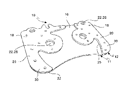
[0020] - figure 1 is a view in the lying plane of a support plate of
a pad for a disc brake according to the invention,
[00M] - figure 2 is a view in the lying plane of a support plate of
a pad for a disc brake according to one embodiment variant of the
invention,
[0022] - figure 3 is a perspective view of a support plate of a pad
for a disc brake according to one embodiment variant of the
invention shown in figure 2,
[0023] - figure 4 is a perspective view of a portion of a support
plate of a pad for a disc brake according to one embodiment variant
of the invention shown in figures 2 and 3,
[0024] - figure 5 is a perspective view of a support plate of a pad
for a disc brake according to a further embodiment variant of the
invention,
[0025] - figure 6 is a perspective view of a support plate of a pad
for a disc brake according to a further embodiment variant of the
invention,
Date Recue/Date Received 2022-09-07
CA 02978386 2017-08-31
WO 2016/139562
PCT/1B2016/051055
[0026] - figure 7 is a perspective view of a support plate
of a pad for a disc brake according to a further
embodiment variant of the invention,
[0027] - figure 8 is a perspective view of a support plate
5 of a pad for a disc brake according to a further
embodiment variant of the invention,
[0028] - figure 9 is a diagrammatical sectional view of a
pad for a disc brake comprising the support plate shown
in figure 1,
[0029] - figure 10 is a diagrammatical sectional view of a
pad for a disc brake comprising the support plate shown
in figure 2,
[0030]- figure 11 is a perspective view of a support plate
of a pad for a disc brake according to a further
embodiment variant of the invention.
[0031] Description of some preferred embodiments
[0032] The elements or parts of elements common to the
embodiments described below will be indicated using the
same numeral.
[0033] With reference to the figures, numeral 1 generally
indicates a pad for a disc of a disc brake.
[0034] Under conditions of use, that is when pad 1 is
mounted on a disc brake calliper body and is facing an
associable brake disc, a radial direction R-R is defined
passing through the center of rotation of a brake disc
CA 02978386 2017-08-31
WO 2016/139562
PCT/1B2016/051055
6
associated with a pad 1 and through any one of the points
belonging to the braking band of the brake disc, and a
tangential T-T or circumferential direction is defined
which is orthogonal to said radial direction R-R;
moreover, an axial direction U-U is defined which is
orthogonal to both the radial direction R-R and the
tangential direction T-T.
[0035] A pad 1 for a disc brake comprises a support plate
and a friction material 5, in which said pad 10 mainly
10 extends in a plane defined, when plate 10 is in use, by
the radial direction R-R and the tangential direction T-
T, which define a lying plane that can face a disc of a
disc brake.
[0036] Said support plate 10 comprises at least one first
plate 11 and at least one second plate 12, in which said
first plate 11 is in single-piece and extends over a
region of said lying plane which defines the footprint of
pad 1 in said lying plane, and in which said first plate
11 comprises a flat piston support surface 14 suitable
for facing at least one thrust means, and a first
friction surface 16 opposite to the piston support
surface 14 and at least partially suitable for facing the
friction material 5.
[0037] In accordance with one embodiment, said piston
support surface 14 is flat and smooth and is made in
CA 02978386 2017-08-31
WO 2016/139562
PCT/1B2016/051055
7
single-piece. This advantageously allows the pressures
transferred from said at least one thrust means to be
distributed to pad 1.
[0038] In accordance with one embodiment, said at least one
thrust means may be e.g. a hydraulically or electrically
actuated piston.
[0039] Said at least one second plate 12 is suitable for
being interposed between said at least one first plate 11
and the friction material 5 and said at least one second
plate 12 is connected to the first plate 11 in a
plurality of junction points 18 which are separate from
one another.
[0040] Advantageously, said plurality of junction points 18
are separate from one another, thus allowing said at
least one first plate 11 and said at least one second
plate 12 to vibrate independently of each other and thus
allowing free portions of said at least one first plate
11 and said at least one second plate 12 to move, for
example to bend, relative to one another and therefore to
dampen the vibrations induced by the braking.
[0041] In accordance with one embodiment, said plurality of
junction points 18 are separate from one another and may
be uniformly distributed on the surface of said second
plate 12.
[0042] In accordance with one embodiment variant, said
junction points 18 are separate from one another and may
CA 02978386 2017-08-31
WO 2016/139562
PCT/1B2016/051055
8
be randomly distributed on the surface of said second
plate 12.
[0043] Said plurality of junction points 18 may be in the
shape of a plurality of welding points or rivets or
threaded connections.
[0044] In accordance with one embodiment, said at least one
first plate 11 and said at least one second plate 12 have
a different thickness, that is an extension in axial
direction U-U.
[0045] In accordance with one embodiment, said at least one
first plate 11 and said at least one second plate 12 have
a substantially equal thickness, that is an extension in
axial direction U-U.
[0046] In accordance with one embodiment, said at least one
first plate 11 and said at least one second plate 12 are
made of a metal material, such as e.g. steel, stainless
steel, cast iron, aluminum or aluminum alloy, and said
plurality of junction points 18 is a plurality of
capacitive welding points.
[0047] Said at least one second plate 12 extends over at
least one portion of the friction surface 16 of said at
least one first plate 11 delimited by a single closed
perimeter, in which at least one portion of the friction
surface 16 of said at least one first plate 11 is
external to said closed perimeter of said at least one
second plate 12 and faces said friction material 5, and
CA 02978386 2017-08-31
WO 2016/139562
PCT/1B2016/051055
9
said at least one second plate 12 defines a second
friction surface 20 facing the friction material 5, which
is continuous.
[0048] Advantageously, said at least one second plate 12
which extends over at least one portion of the friction
surface 16 of said at least one first plate 11 allows the
mass and/or rigidity of the support plate 10 to be
locally modified, and therefore the own vibration
frequency of pad 1 to be modified. Generally, said at
least one second plate 12 is designed so as to allow pad
1 to vibrate at a low frequency, or at a lower frequency
than known solutions, thus generating an anti-rattling
effect.
[0049] Advantageously, the size of the shape of the first
plate 11 makes pad 1 compatible with disc brake callipers
existing prior to the invention and available on the
market for some time; this allows pads which are
obsolete, both due to wear and design, to be replaced
with new pads in accordance with the present invention.
[0050] In accordance with one embodiment, said second
friction surface 20 is devoid of openings that expose the
friction material 5 directly to said first friction
surface 16.
[0051] In accordance with one embodiment, said second
friction surface 20 is free from openings inside said
single closed perimeter, which openings allow said
CA 02978386 2017-08-31
WO 2016/139562
PCT/1B2016/051055
friction material 5 to be put into communication with
said first friction surface 16 inside said closed
perimeter.
[0052]In accordance with one embodiment variant, said
5 second continuous friction surface 20 is interrupted
inside said single closed perimeter only by at least one
through opening 22 which crosses either said at least one
second plate 12 and said at least one first plate 11
and/or by recesses in said at least one second plate 12
10 at said plurality of junction points 18.
[0053] In accordance with one embodiment, said openings may
be e.g. slots 26 for accommodating pins, or cooling holes
28.
[0054] Said second plate 12 extends over the first plate 11
so as to delimit a seat 24 suitable for accommodating the
friction material 5 and in which at least one portion of
said friction material 5 is accommodated and
geometrically coupled in such a seat 24.
[0055] Advantageously, said seat 24 suitable for
accommodating the friction material 5 allows said
friction material 5 to firmly grip the support plate 10
and therefore to resist the stresses deriving from the
braking action while coupled.
[0056] In accordance with one embodiment, said second plate
12 comprises at least one stiffening rib 30 which extends
along a curved edge 32 of the first plate 11.
CA 02978386 2017-08-31
WO 2016/139562
PCT/1B2016/051055
11
[0057] In accordance with one embodiment variant, at least
one stiffening rib 30 extends along a radial edge 33 of
said first plate, that is an edge which extends along the
edges of the plate which are parallel to the radial
direction R-R.
[0058] It is apparent from an analysis made by the
inventors that the portions of edges 32, 33, particularly
but not exclusively the portions of radial edge 33, of
the support plate 10 are the portions most stressed by
the vibrations in terms of amplitude of the movements.
[0059] Therefore, when said at least one stiffening rib 30
is positioned along a curved edge 32 or along a radial
edge 33 of said first plate 11, it advantageously allows
the mass and the rigidity of the support plate 10 to be
locally modified in the areas of edge 32, 33, thus
dampening the vibrations of pad 1 caused by the braking
action and modifying precisely the vibration frequency of
pad 1.
[0060] Advantageously, said at least one stiffening rib 30
positioned along a radial edge 33 of said first plate 11
allows the friction material 5 to grip to a side 25 of
said second plate 12 which delimits said seat 24, even
more firmly, during the tangential stresses, that is in
the direction parallel to T-T, which occur during the
braking action.
CA 02978386 2017-08-31
WO 2016/139562
PCT/1B2016/051055
12
[0061] Said side 25 indeed cooperates with said friction
material 5 to affect the friction material in tangential
direction, that is parallel to T-T.
[0062] In accordance with one embodiment, said second plate
12 comprises at least one stiffening island 34.
[0063] In accordance with one embodiment variant, said
second plate 12 comprises at least two separate
stiffening islands 34.
[0064] In accordance with a further embodiment variant,
said at least two stiffening islands 34 are connected by
means of at least one bridge portion 36 of said at least
one second plate 12.
[0065] In accordance with one embodiment variant, said at
least one second plate 12 comprises said second
continuous friction surface 20, in which said second
continuous friction surface 20 is interrupted inside said
single closed perimeter by at least one through opening
22 which crosses either said at least one second plate 12
and said at least one first plate 11, and in which said
first friction surface 16 is interrupted by through holes
22, such as for example cooling holes 28, positioned in
portions of said first plate 11 suitable for facing said
friction material 5, i.e. external to said closed
perimeter of said second plate 12.
[0066] Those skilled in the art, in order to meet
contingent needs and specifications, may make several
CA 02978386 2017-08-31
WO 2016/139562
PCT/IB2016/051055
13
changes, adaptations and substitutions of elements with
others which are functionally equivalent to the above-
described embodiments, without departing from the scope
of the following claims.
CA 02978386 2017-08-31
WO 2016/139562
PCT/IB2016/051055
14
LIST OF REFERENCES
1. pad
5. friction material
10. support plate
11. first plate
12. second plate
14. flat piston support surface
16. friction surface
18. junction points
20. second friction surface
22. through opening
24. seat for the friction material
25. side
26. slot
28. cooling hole
30. stiffening rib
32. curved edge
33. radial edge
34. stiffening island
36. bridge portion
R-R. radial direction
T-T. tangential direction
U-U. axial direction