Sélection de la langue

Search

Sommaire du brevet 2978513 

Énoncé de désistement de responsabilité concernant l'information provenant de tiers

Une partie des informations de ce site Web a été fournie par des sources externes. Le gouvernement du Canada n'assume aucune responsabilité concernant la précision, l'actualité ou la fiabilité des informations fournies par les sources externes. Les utilisateurs qui désirent employer cette information devraient consulter directement la source des informations. Le contenu fourni par les sources externes n'est pas assujetti aux exigences sur les langues officielles, la protection des renseignements personnels et l'accessibilité.

Disponibilité de l'Abrégé et des Revendications

L'apparition de différences dans le texte et l'image des Revendications et de l'Abrégé dépend du moment auquel le document est publié. Les textes des Revendications et de l'Abrégé sont affichés :

  • lorsque la demande peut être examinée par le public;
  • lorsque le brevet est émis (délivrance).
(12) Demande de brevet: (11) CA 2978513
(54) Titre français: DISPOSITIF D'APPLICATION D'EFFORT D'UN FREIN A DISQUE
(54) Titre anglais: BRAKE APPLICATION MECHANISM OF A DISK BRAKE
Statut: Réputée abandonnée et au-delà du délai pour le rétablissement - en attente de la réponse à l’avis de communication rejetée
Données bibliographiques
(51) Classification internationale des brevets (CIB):
  • F16D 65/18 (2006.01)
  • F16D 65/56 (2006.01)
(72) Inventeurs :
  • BECK, THOMAS (Allemagne)
  • HIDRINGER, MICHAEL (Allemagne)
  • PRITZ, WOLFGANG (Allemagne)
(73) Titulaires :
  • KNORR-BREMSE SYSTEME FUR NUTZFAHRZEUGE GMBH
(71) Demandeurs :
  • KNORR-BREMSE SYSTEME FUR NUTZFAHRZEUGE GMBH (Allemagne)
(74) Agent: SMART & BIGGAR LP
(74) Co-agent:
(45) Délivré:
(86) Date de dépôt PCT: 2016-02-23
(87) Mise à la disponibilité du public: 2016-09-09
Licence disponible: S.O.
Cédé au domaine public: S.O.
(25) Langue des documents déposés: Anglais

Traité de coopération en matière de brevets (PCT): Oui
(86) Numéro de la demande PCT: PCT/EP2016/053700
(87) Numéro de publication internationale PCT: EP2016053700
(85) Entrée nationale: 2017-09-01

(30) Données de priorité de la demande:
Numéro de la demande Pays / territoire Date
102015103088.8 (Allemagne) 2015-03-04

Abrégés

Abrégé français

L'invention concerne un dispositif d'application d'effort d'un frein à disque, qui comprend une plaque de pression (13), venant au contact d'une garniture de frein, et un élément cylindrique taraudé, maintenu sur ladite plaque de pression de manière bloquée en rotation. Selon l'invention, la plaque de pression (13) et l'élément taraudé relié à celle-ci sont réalisés sous forme de pièces séparées.


Abrégé anglais

A brake application mechanism of a disk brake comprises a pressure piece (13) in contact with a brake pad, and a cylindrical threaded element that is retained on the pressure piece in such a way as to rotate therewith; the pressure piece (13) and the threaded element that is connected thereto are designed as separate parts.

Revendications

Note : Les revendications sont présentées dans la langue officielle dans laquelle elles ont été soumises.


8
Claims
1. A brake application mechanism of a disk brake, having a
pressure piece (13) which makes contact with a brake lining (3),
and a cylindrical threaded element which is held in a
rotationally fixed manner on said pressure piece (13),
characterized in that the pressure piece (13) and the threaded
element which is connected to it are configured as separate
components.
2. The brake application mechanism as claimed in claim 1,
characterized in that the threaded element is configured as a
threaded sleeve (7).
3. The brake application mechanism as claimed in claim 1 or 2,
characterized in that the pressure piece (13) and the threaded
element (7) are connected fixedly to one another in an integrally
joined, frictionally locking or positively locking manner.
4. The brake application mechanism as claimed in one of the
preceding claims, characterized in that the threaded element is
screwed to the pressure piece (13).
5. The brake application mechanism as claimed in one of the
preceding claims, characterized in that the screw connection is
secured against rotation.
6. The brake application mechanism as claimed in one of the
preceding claims, characterized in that the pressure piece (13)
and the threaded element (7) consist of different materials, in
particular different iron materials.
7. The brake application mechanism as claimed in one of the
preceding claims, characterized in that the threaded element and

9
the pressure piece (13) are connected to one another by way of
rotary friction welding or fusion welding.
8. The brake application mechanism as claimed in one of the
preceding claims, characterized in that the pressure piece (13)
is formed from cast iron.
9. The brake application mechanism as claimed in one of the
preceding claims, characterized in that the threaded element is
configured as an extruded part or a cold extruded part.
10. The brake application mechanism as claimed in one of the
preceding claims, characterized in that the pressure piece (13)
is configured as a forged part.

Description

Note : Les descriptions sont présentées dans la langue officielle dans laquelle elles ont été soumises.

CA 02978513 2017-09-01
1
Brake application mechanism of a disk brake
The invention relates to a brake application mechanism of a disk
brake in accordance with the preamble of claim 1.
A brake application mechanism of this type is known from DE 10
2006 010 754 Al. Said brake application mechanism has a centrally
arranged, brake ram which can be pressed via a brake lever onto
the brake application-side brake lining of a disk brake, with a
threaded sleeve, onto which a pressure piece is integrally formed
on its side which faces the brake lining, via which pressure
piece the threaded sleeve is connected to the brake lining in a
rotationally fixed manner.
In order to compensate for an air play, that is to say in order
to compensate for a spacing between the brake lining and a brake
disk, which spacing changes in a wear-induced manner, the
threaded sleeve is mounted on an actuating spindle which is
provided with an external thread and can be rotated by means of
an adjusting device for air play compensation, that is to say for
adjustment of the brake lining, with a simultaneous axial
movement of the threaded sleeve.
In a brake application mechanism which is known from WO 2014/001
456 Al, the pressure piece and the threaded sleeve (which forms a
threaded element in the sense of the generic type) are likewise
configured in one piece, usually by way of casting. It is not
taken into consideration here that different requirements are
made of the pressure piece and the threaded sleeve, not least
with regard to their different spatial shape.
Whereas the threaded sleeve is of substantially round cross
section and is relatively long in relation to this, the pressure
piece is flat and wide.

CA 02978513 2017-09-01
2
In addition to the absence of the possibility of meeting the
different requirements made firstly of the pressure piece and
secondly of the threaded sleeve with regard to the material
selection, the known brake application mechanism also makes no
contribution to the constant demand for weight optimization of
all components of a commercial vehicle, the aim of which is a
reduction in the fuel consumption and, as a consequence, in the
CO2 emissions.
This is the case above all because, as has been mentioned, the
single-piece configuration of the cylindrical threaded
element/pressure piece unit is configured as a cast component,
that is to say necessitates material thicknesses which are
conditional on casting technology.
The invention is based on the object of developing a brake
application mechanism of the generic type in such a way that it
can be produced simpler and less expensively and is optimized in
terms of material and weight with an identical load-bearing
capacity.
Said object is achieved by way of a brake application mechanism
having the features of claim 1.
By virtue of the fact that, according to the invention, the
pressure piece and the threaded element which is connected to it
are configured as separate components, there is now the
possibility of adapting each of the two components individually
to the respective requirements, in particular with regard to
their loading, both in relation to the dimensioning and in
relation to the material to be used.
According to one preferred concept of the invention, the threaded
element is produced using the extrusion process with preforming

,
CA 02978513 2017-09-01
,
3
of the outer and the inner geometry, with the result that only a
little re-machining is required.
It is also conceivable, however, to produce the threaded element
using other suitable forming or primary forming processes, such
as cold extrusion or the like. The pressure piece in turn can be
produced using the sand casting process or by way of forging. It
goes without saying that other forming processes are also
conceivable here, just like a material selection which is
inspired by the requirements.
As a result, a reduction in the production costs is achieved
overall, just like there is the option of a material mix of the
structural unit which contributes to an optimization of the
operability. This also otherwise applies to the geometries and
dimensions of the involved components, which can be selected in
accordance with the respective requirements.
A further advantage results from the targeted dimensioning which
is then possible, in so far as the brake application mechanism
can be produced with a reduced weight or an optimized weight as a
result, which complies with the constant demands for this, as
mentioned.
The connection of the threaded element to the pressure piece in
such a way that both are held in a rotationally locked manner
with respect to one another is likewise possible in different
ways. These include a frictionally locking, integrally joined or
positively locking connection.
Otherwise, no substantial preparation work is required for the
integrally joined connection which is preferably produced by way
of rotary friction welding which manages substantially without
welding filler materials.

CA 02978513 2017-09-01
4
In addition, rotary friction welding is also suitable, in
particular, for connecting different materials, iron metals such
as steel and/or cast iron preferably being used here.
The very small heat affected zone which is produced during rotary
friction welding is also particularly advantageous for the
realization of the invention, since warping, in particular of the
threaded element, by way of thermal stresses is substantially
avoided.
It goes without saying that there is also the possibility of
using other welding processes, for example fusion welding, said
welding processes likewise being carried out in an automated
manner like the rotary friction welding.
For a frictionally locking connection for connecting the two
components to one another, corresponding receptacles for
producing an interference fit are to be prepared.
Different measures are likewise conceivable for the positively
locking connection, for example a screw connection, corresponding
securing measures ensuring that said screw connection is not
released automatically by way of the vibrations which occur
during driving operation of the commercial vehicle. For instance,
notches can be provided to this end, which achieve an anti-
rotation safeguard.
Molded projections which correspond with one another can likewise
be provided on the pressure piece and/or threaded element as
positively locking elements which engage into one another, for
example by being bent over, in such a way that both an axial
movement safeguard and an anti-rotation safeguard are ensured.
Further advantageous refinements of the invention are
characterized in the subclaims.

CA 02978513 2017-09-01
One exemplary embodiment of the invention will be described in
the following text using the appended drawings, in which:
5 figure 1 shows a disk brake which is provided with a brake
application mechanism according to the invention,
in a sectioned plan view, and
figure 2 shows a part of the brake application mechanism in
different manufacturing steps, in each case in a
perspective view.
A diagrammatic illustration of a disk brake can be seen in figure
1, having a brake caliper 1 which engages over a brake disk 2, is
configured as a sliding caliper, and in which two brake linings 3
are arranged which can be pressed against the brake disk 2 in the
functional state, that is to say during a braking operation.
Here, first of all the brake application-side brake lining 3 is
pressed against the brake disk 2 by means of a brake application
mechanism 8, whereas subsequently, on account of the reaction
forces, the reaction-side brake lining 3 is pressed against the
brake disk 2 by way of the driving of the brake caliper 1 which
is displaced.
Each brake lining 3 consists of a lining carrier plate 11 and a
friction lining 12 which is fastened thereon and makes contact
with the brake disk 2 during a braking operation.
In each case one lining holding spring 9 is fastened to the
lining carrier plates 11, which lining holding springs 9, in
interaction with a holding bracket 10, hold the brake linings 3
under prestress in a brake shaft of the brake caliper 1 or of a
brake carrier.

CA 02978513 2017-09-01
=
6
The brake application mechanism 8 has a brake ram 4 which,
arranged centrally, can be pressed against the brake application-
side brake lining 3 in an axially displaceable manner via a brake
lever 14.
Here, the brake ram 4 consists of an actuating spindle 6, to
which an adjusting device 5 for compensating for an air play is
connected, and a threaded sleeve 7 which engages with an internal
thread into an external thread of the actuating spindle 6.
On its side which faces the lining carrier plate 11 of the brake
application-side brake lining 3, the threaded spindle 7 is
connected fixedly to a plate-shaped pressure piece 13 which bears
against the lining carrier plate 11.
In order to prevent the threaded sleeve 7 and therefore the
pressure piece 13 from corotating during a rotation of the
actuating spindle 6 in order to compensate for the air play, said
pressure piece 13 is held on the lining carrier plate 11 in a
manner which is secured against rotation.
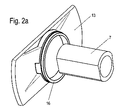
Figure 2 shows, as a detail, the pressure piece 13 and the
threaded sleeve 7 which forms a threaded element, which are
configured as separate components according to the invention, as
can be seen particularly clearly in figure 2a). A position is
depicted here before the threaded sleeve 7 is connected fixedly
to the pressure piece 13 by way of a suitable joining process.
The threaded sleeve 7/pressure Diece 13 structural unit is
depicted in figure 2b) in a connected arrangement, that is to say
ready for use.
In the example, the threaded sleeve 7 is connected on the
pressure piece 13 centrally by way of, for example, welding, such
as rotary friction welding or fusion welding, identified by way
of a welded seam 15.

CA 02978513 2017-09-01
7
Otherwise, an elevated ring 16 is integrally formed on the
pressure piece 13 on the side which faces the threaded sleeve 7,
concentrically with respect thereto, to which ring 16 a gaiter 17
which can be seen in figure 1 is connected in a functional state.
As has already been stated, other joining processes are also
conceivable for connecting the threaded sleeve 7 and the pressure
piece 13, in addition to the abovementioned integrally joined,
frictionally locking or positively locking connection.

Dessin représentatif
Une figure unique qui représente un dessin illustrant l'invention.
États administratifs

2024-08-01 : Dans le cadre de la transition vers les Brevets de nouvelle génération (BNG), la base de données sur les brevets canadiens (BDBC) contient désormais un Historique d'événement plus détaillé, qui reproduit le Journal des événements de notre nouvelle solution interne.

Veuillez noter que les événements débutant par « Inactive : » se réfèrent à des événements qui ne sont plus utilisés dans notre nouvelle solution interne.

Pour une meilleure compréhension de l'état de la demande ou brevet qui figure sur cette page, la rubrique Mise en garde , et les descriptions de Brevet , Historique d'événement , Taxes périodiques et Historique des paiements devraient être consultées.

Historique d'événement

Description Date
Le délai pour l'annulation est expiré 2021-08-31
Demande non rétablie avant l'échéance 2021-08-31
Réputée abandonnée - omission de répondre à un avis relatif à une requête d'examen 2021-05-17
Inactive : COVID 19 Mis à jour DDT19/20 fin de période de rétablissement 2021-03-13
Lettre envoyée 2021-02-23
Représentant commun nommé 2020-11-07
Réputée abandonnée - omission de répondre à un avis sur les taxes pour le maintien en état 2020-08-31
Inactive : COVID 19 - Délai prolongé 2020-08-19
Lettre envoyée 2020-02-24
Représentant commun nommé 2019-10-30
Inactive : Page couverture publiée 2017-09-26
Inactive : CIB en 1re position 2017-09-22
Inactive : Notice - Entrée phase nat. - Pas de RE 2017-09-15
Inactive : CIB attribuée 2017-09-12
Demande reçue - PCT 2017-09-12
Exigences pour l'entrée dans la phase nationale - jugée conforme 2017-09-01
Demande publiée (accessible au public) 2016-09-09

Historique d'abandonnement

Date d'abandonnement Raison Date de rétablissement
2021-05-17
2020-08-31

Taxes périodiques

Le dernier paiement a été reçu le 2019-02-15

Avis : Si le paiement en totalité n'a pas été reçu au plus tard à la date indiquée, une taxe supplémentaire peut être imposée, soit une des taxes suivantes :

  • taxe de rétablissement ;
  • taxe pour paiement en souffrance ; ou
  • taxe additionnelle pour le renversement d'une péremption réputée.

Les taxes sur les brevets sont ajustées au 1er janvier de chaque année. Les montants ci-dessus sont les montants actuels s'ils sont reçus au plus tard le 31 décembre de l'année en cours.
Veuillez vous référer à la page web des taxes sur les brevets de l'OPIC pour voir tous les montants actuels des taxes.

Historique des taxes

Type de taxes Anniversaire Échéance Date payée
Taxe nationale de base - générale 2017-09-01
TM (demande, 2e anniv.) - générale 02 2018-02-23 2018-02-14
TM (demande, 3e anniv.) - générale 03 2019-02-25 2019-02-15
Titulaires au dossier

Les titulaires actuels et antérieures au dossier sont affichés en ordre alphabétique.

Titulaires actuels au dossier
KNORR-BREMSE SYSTEME FUR NUTZFAHRZEUGE GMBH
Titulaires antérieures au dossier
MICHAEL HIDRINGER
THOMAS BECK
WOLFGANG PRITZ
Les propriétaires antérieurs qui ne figurent pas dans la liste des « Propriétaires au dossier » apparaîtront dans d'autres documents au dossier.
Documents

Pour visionner les fichiers sélectionnés, entrer le code reCAPTCHA :


Pour visualiser une image, cliquer sur un lien dans la colonne description du document. Pour télécharger l'image (les images), cliquer l'une ou plusieurs cases à cocher dans la première colonne et ensuite cliquer sur le bouton "Télécharger sélection en format PDF (archive Zip)" ou le bouton "Télécharger sélection (en un fichier PDF fusionné)".

Liste des documents de brevet publiés et non publiés sur la BDBC .

Si vous avez des difficultés à accéder au contenu, veuillez communiquer avec le Centre de services à la clientèle au 1-866-997-1936, ou envoyer un courriel au Centre de service à la clientèle de l'OPIC.


Description du
Document 
Date
(aaaa-mm-jj) 
Nombre de pages   Taille de l'image (Ko) 
Description 2017-08-31 7 256
Dessins 2017-08-31 2 43
Revendications 2017-08-31 2 51
Dessin représentatif 2017-08-31 1 9
Abrégé 2017-08-31 1 9
Avis d'entree dans la phase nationale 2017-09-14 1 193
Rappel de taxe de maintien due 2017-10-23 1 112
Avis du commissaire - non-paiement de la taxe de maintien en état pour une demande de brevet 2020-04-05 1 536
Courtoisie - Lettre d'abandon (taxe de maintien en état) 2020-09-20 1 552
Avis du commissaire - Requête d'examen non faite 2021-03-15 1 542
Avis du commissaire - non-paiement de la taxe de maintien en état pour une demande de brevet 2021-04-05 1 528
Courtoisie - Lettre d'abandon (requête d'examen) 2021-06-06 1 553
Rapport de recherche internationale 2017-08-31 3 78
Modification - Abrégé 2017-08-31 2 70
Demande d'entrée en phase nationale 2017-08-31 3 63