Note : Les descriptions sont présentées dans la langue officielle dans laquelle elles ont été soumises.
1
Plate holder for holding a license plate, in particular comprising a radio
frequency
transponder
[0001] The invention relates to a plate holder for holding a license plate.
[0002] A plate holder of this type comprises a holder base having, on a first
side, a contact
surface, which extends along a contact plane. A license plate rests on the
contact surface
when it is placed on the plate holder. Arranged on the holder base are two
guide rails
extending parallel to each other, between which the license plate can be slid
in an insertion
direction for arrangement on the contact surface. In a position arranged on
the plate holder,
the guide rails hold the license plate on the holder base.
[0003] License plates may nowadays have, for example, radio frequency
transponders (also
called "RFID tags"), which can be read out by a suitable reader by inductive
coupling and are
configured to exchange data with the reader (using, for example, so-called
"Near Field
Communication", for short "NFC"). If a license plate is to be arranged via a
plate holder on a
metal object, for example a metal housing of an industrial plant, a switch
cabinet or the like,
the metal object may impair the communication properties of a radio frequency
transponder
of this type if the radio frequency transponder comes to rest too close to the
metal object.
[0004] It is therefore necessary, in a plate holder of this type, which is to
be used for
attachment of a license plate having a radio frequency transponder on a metal
object, to
leave sufficient space between the contact surface and the metal object in
order to reduce as
far as possible an impairment of the communication properties of the radio
frequency
transponder.
[0005] However, if a plate holder is too far from the object to which it has
been attached, this
can lead, for example, to the clothes of a user getting caught on the plate
holder or a user
bumping against the plate holder, which may possibly entail a risk of injury
and is therefore to
be avoided for the purposes of a safe working environment.
CA 2978648 2019-01-23
2
[0006] A plate holder for a license plate is known from DE 197 43 405 Al, in
which a plate
can be arranged between guide rails on a contact surface. The plate holder of
DE 197 43
405 Al is designed to arrange a license plate on a line.
[0007] In a plate holder known from DE 20 2011 000 569 U1, a license plate is
arranged on
a base body 2 by means of rivet connections. A radio frequency transponder,
which can be
read out electronically, is arranged on the license plate.
[0008] It is desirable to provide a plate holder, which can be favorably
arranged on an object,
in particular a metal object, and in the process leave sufficient space
between a contact
surface and the metal object, with nevertheless a low risk of, for example,
clothes getting
caught on the plate holder.
[0009] In one aspect, the present invention provides a plate holder (1) for
holding a license
plate (2), comprising a holder base (10) having, on a first side, a contact
surface (100), which
extends along a contact plane (A) and on which a license plate (2) rests in a
position
arranged on the plate holder (1), and two guide rails (11, 12), which are
arranged on the
holder base (10) and extend parallel to each other and between which the
license plate (2)
can be slid in an insertion direction (E) for arrangement on the contact
surface (100), the
license plate (2) being held between the guide rails (11, 12) in the position
arranged on the
plate holder (1), characterized in that the holder base (10) has, on a second
side facing away
from the contact surface (100), a placement surface (102), which extends
parallel to the
contact plane (A), is spaced apart from the contact surface (100) in a
vertical direction (Z)
pointing perpendicularly to the contact plane (A), and can be placed on an
object (3) in order
to arrange the plate holder (1) on the object (3), the holder base (10)
tapering from the
second side to the first side.
[0010] Accordingly, the holder base, on a second side facing away from the
contact surface,
has a placement surface, which extends parallel to the contact plane, is
spaced apart from
the contact surface in a vertical direction pointing perpendicularly to the
contact plane, and
can be placed on an object in order to arrange the plate holder on the object,
the holder base
tapering from the second side to the first side.
CA 2978648 2019-01-23
2a
[0011] The possibility is provided by means of the placement surface to
favorably place the
plate holder in flat abutment on an associated object. By means of the
placement surface,
the holder base can, for example, be screwed or glued to the object or
otherwise fastened to
the object.
[0012] The placement surface is spaced apart from the contact surface such
that a license
plate can be held on the contact surface so as to leave sufficient space from
the placement
surface and therefore from the object on which the plate holder is to be
arranged.
[0013] The holder base has a shape, here, which tapers from the second side to
the first
side. The holder base therefore extends from the second side, on which the
placement
surface is
CA 2978648 2019-01-23
CA 02978648 2017-09-05
3
formed, to the first side, on which the contact surface is formed, in a
tapering manner, as a
result of which the risk of, for example, clothes getting caught on the plate
holder is reduced.
[0014] In particular, the holder base, on the second side, may have a greater
length, measured
in the insertion direction, and/or a greater width, measured transversely to
the insertion
direction, than on the first side. The dimensions of the holder base on the
first side are therefore
smaller than on the second side.
[0015] The holder base preferably has one or more peripheral side surfaces.
The side surfaces
connect the first side and the second side to each other and are hereby
advantageously placed
obliquely with respect to the contact plane in such a way that the holder base
tapers toward the
first side, in other words toward the contact surface.
[0016] For example, the holder base may have the shape of a truncated cone. In
this case, the
holder base has a peripheral side surface, which corresponds to the outer
lateral surface of the
truncated cone. In this case, the holder base extends conically toward the
first side.
[0017] Alternatively, the holder base may also have a rectangular, for example
elongate or
square, base surface. In this case, the holder base has four side surfaces,
which are in each
case placed obliquely to the contact plane and form a truncated pyramid.
[0018] The one or more side surfaces peripherally enclose the holder base and
advantageously
have no openings, undercuts, projections or the like, such that the snagging
of clothes or other
objects on the plate holder is prevented and, for example, clothes can easily
slip off the plate
= holder.
[0019] In a specific embodiment, the holder base, on the first side thereof,
may have an at least
approximately rectangular base surface. In this case, the holder base, in
cross section along a =
first cross-sectional plane, which is spanned by the insertion direction and
the vertical direction,
and/or along a second cross-sectional plane, which is spanned by the vertical
direction and a
transverse direction pointing transversely to the insertion direction and to
the vertical direction,
may have the shape of an isosceles trapezium. In cross section along the first
cross-sectional
plane and/or in cross section along the second cross-sectional plane, the
holder base therefore
CA 02978648 2017-09-05
4
has a trapezoidal shape with sides of equal length, the sides being formed by
opposing side
surfaces of the holder base and the (parallel) base sides of the trapezium
being formed by the
first side and the second side of the holder base.
[0020] In an advantageous embodiment, the placement surface has at least one
fastening point
for fastening the plate holder on the object. The fastening point may, for
example, be designed
to attach a screw or rivet connection such that, by means of the placement
surface, the plate
holder can be fastened to the object by screws or rivets.
[0021] In order to be able to access the fastening points, at least one
opening may be provided
here in the contact surface, which extends along the contact plane extending
parallel to the
placement surface, by means of which opening a tool, for example, can be
placed on the
fastening point of the placement surface in order to fasten the plate holder
on the object.
[0022] In addition or alternatively, the placement surface may also have an
adhesive layer
comprising a removable protective film. The protective film covers the
adhesive layer in an initial
state such that the plate holder may, for example, be delivered to a user of
the plate holder with
the adhesive layer covered. The protective film is removed in order to fasten
the plate holder to
an object, such that the placement surface together with the adhesive layer
can be pressed
against the object in order to bring the adhesive layer into adhesive contact
with the object.
[0023] In an advantageous embodiment, the plate holder has at least one
resilient latching
element, which is arranged on the holder base and is elastically deformable
when the license
plate is arranged on the plate holder and, in the position arranged on the
plate holder, fixes the
license plate on the holder base against a movement in the insertion
direction. By providing the
resilient latching element, it is possible to easily place a license plate,
which is optionally rigid
per se, on the plate holder and also to release the license plate from the
plate holder without
tools. In order to place a license plate on the plate holder, the license
plate is slid between the
guide rails. The license plate hereby runs onto the at least one latching
element and pushes it
aside in a resilient manner such that the license plate can be inserted into
the plate holder over
the latching element. Once the license plate has reached its provided seat on
the holder base,
the latching element snaps back into its starting position and comes into
latching engagement,
CA 02978648 2017-09-05
for example with an edge of the license plate, such that the license plate is
fixed on the holder
base by means of the latching element against a movement in the insertion
direction.
[0024] A license plate can therefore be easily placed on the plate holder by
pushing aside the
latching element without the license plate having to be deformed. Since, when
the license plate
has reached its provided position on the plate holder, the latching element
snaps into latching
engagement with the license plate and therefore permanently fixes it on the
plate holder, a
reliable hold of the license plate on the plate holder is provided.
[0025] In order to release the license plate from the plate holder, the at
least one latching
element may be deformed in such a way that the license plate is released for
displacement in
the insertion direction and can therefore be slid out of the plate holder. The
elastic deformation
of the latching element can take place without tools in that a user, for
example, manually grasps
the latching element and presses it out of engagement with the license plate.
Deformation of the
license plate is therefore not necessary for release from the plate holder,
and therefore even
rigid license plates, which cannot readily be deformed, can be easily arranged
on the plate
holder and can also be easily released again from the plate holder.
[0026] In an advantageous embodiment, the plate holder has two latching
elements, which are
arranged on the holder base so as to be offset from each other in the
insertion direction. In the
position arranged on the plate holder, the latching elements receive the
license plate between
them, for example, in that a first latching element comes to rest on a first
edge of the license
place extending transversely to the guide rails and a second latching element
comes to rest on
a second edge of the license plate extending transversely to the guide rails,
and therefore the
license plate is fixed in an interlocking manner on the holder base in the
insertion direction.
[0027] The at least one latching element, in a specific embodiment, is formed
by a resilient web,
which is connected to the contact surface. The web may, for example, be cut
out from the
contact surface via slot-shaped openings, such that a latching element in the
manner of a
latching tongue is produced, which can be moved in a resilient manner with
respect to the
contact surface. A latching projection, which rises above the contact surface
and therefore
provides a stop for the license plate, is preferably arranged on the at least
one latching element.
When placing the license plate on the plate holder, the license plate runs
onto the latching
CA 02978648 2017-09-05
6
projection of the latching element and therefore pushes the latching element
aside. If the license
plate has reached its provided position on the plate holder, the latching
projection snaps into
engagement, for example with an edge of the license plate, such that the edge
comes into
abutment with the latching projection and the license plate is thus fixed on
the plate holder
against a displacement in the insertion direction.
[0028] By means of the latching projection, the license plate is fixed on the
plate holder in a
latching manner such that the license plate is prevented from sliding out of
its seat between the
guide rails. In addition, the at least one latching element may have an
elevation projecting from
the contact surface, which is designed to come into abutment with a lower side
of the license
plate facing the contact surface in the position of the license plate arranged
on the plate holder.
The elevation may, for example, be rounded in a lenticular manner such that
the license plate
can easily run onto the elevation upon insertion into the plate holder. Once
the license plate has
been placed on the plate holder, the elevation presses from below against the
license plate and
therefore presses it into abutment with the guide rails perpendicularly to the
contact surface
such that the license plate is held on the guide rails without clearance and
rattling.
[0029] In addition, a fastening point for fastening the license plate on the
holder base may be
arranged on the at least one latching element. The fastening point may, for
example, be
designed to attach a rivet or screw connection, such that the license plate,
when it has been
placed on the plate holder, can additionally be fastened on the plate holder
by means of the
fastening point over and above the latching connection provided by the at
least one latching
element.
[0030] In order to access the latching element on the contact surface, in an
advantageous
embodiment, at least one opening may be provided on the placement surface, by
means of
which opening the latching element, in particular the fastening point provided
on the latching
element, can be accessed.
[0031] A license plate, which comprises a radio frequency transponder, may
advantageously be
arranged on the plate holder. Since the distance between the contact surface
and the
placement surface is suitably selected, the license plate can be arranged at a
sufficient distance
from, for example, a metal object, such that the communication properties of
the radio frequency
CA 02978648 2017-09-05
7
= transponder of the license plate are not (excessively) impaired by the
metal object. Depending
on the type and design of the license plate, different plate holders, which in
each case provide a
suitable distance between the contact surface and placement surface, may be
used here.
[0032] The concept upon which the invention is based will be described in more
detail below
with reference to the embodiments shown in the drawings, in which:
[0033] Fig. 1 is a perspective view of an embodiment of a plate holder;
[0034] Fig. 2 is a perspective view of the plate holder, with a license plate
arranged thereon;
[0035] Fig. 3 is a perspective view of the plate holder from below;
[0036] Fig. 4A is a view of the plate holder on an object;
[0037] Fig. 4B is a sectional view along the line A-A according to Fig. 4A;
[0038] Fig. 5 is a view of a second embodiment of a plate holder, with a
license plate arranged
thereon;
[0039] Fig. 6 is a perspective view of the plate holder according to Fig. 5,
obliquely from below;
[0040] Fig. 7A is a view of the plate holder according to Fig. 1, with
cross-sectional
planes drawn in;
[0041] Fig. 7B is a schematic cross-sectional view along a first cross-
sectional plane 01
according to Fig. 7A; and
[0042] Fig. 70 is a schematic cross-sectional view along a second cross-
sectional plane
Q2 according to Fig. 7A.
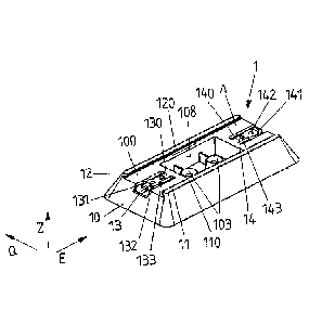
[0043] Fig. 1 to 4A, 4B show a first embodiment of a plate holder 1, which is
used to hold a
license plate 2 and to fasten the license plate 2 on an object 3. The plate
holder 1 is, in
CA 02978648 2017-09-05
8
particular, designed for fastening on a planar surface of an object 3, for
example a metal
housing of a plant, for example a switch cabinet or the like.
[0044] The plate holder 1 has a holder base 10, which forms a contact surface
100 on a first
side. A license plate 2 can be arranged on the contact surface 100 in that the
license plate 2 is
slid in an insertion direction E between guide rails 11, 12 arranged laterally
on the contact
surface 100.
[0045] The contact surface 100 extends in a contact plane A, which is spanned
by the insertion
direction E and a transverse direction Q. In a vertical direction Z transverse
to the insertion
direction E and transverse to the transverse direction Q, spaced apart from
the contact surface
100, a placement surface 102 is formed on a second side of the holder base 10,
by means of
which the holder base 10 can be placed on the object 3 in a planar manner.
[0046] Fastening points 103, by means of which the holder base 10 can, for
example, be
screwed or riveted to the object, are provided on the placement surface 102.
[0047] Alternatively, the holder base 10 can be fastened to the object 3 by
gluing the placement
surface 102 to the object 3.
[0048] The plate holder 1 has a tapering shape from the second side, on which
the placement
surface 102 is formed, to the first side, on which the contact surface 100 is
formed. The holder
base 10 has a substantially rectangular base surface on the second side, the
dimensions of
which, in particular the length L measured in the insertion direction E and
the width B measured
in the transverse direction 0, are greater than the dimensions on the first
side of the holder base
10.
[0049] The holder base 10 is closed on the outer peripheral surface thereof
extending between
the first side and the second side by means of side surfaces 104 to 107. The
side surfaces in
each case extend obliquely to the vertical direction Z, in that they, for
example, define an angle
between 20 and 70 , for example between 30 and 60 to the vertical direction
Z.
CA 02978648 2017-09-05
9
[0050] Because of the obliquely placed side surfaces 104 to 107, the holder
base 10 has a
trapezoidal shape in cross section, as illustrated in Fig. 7A to 7C. Thus, the
holder base 10 is
trapezoidal both in a first cross-sectional plane Q1 spanned by the insertion
direction E and the
vertical direction Z and in a second cross-sectional plane Q2 spanned by the
vertical direction Z
and the transverse direction Q. The holder base 10 forms an isosceles
trapezium, in which the
contact surface 100 and the placement surface 102 are the base sides running
parallel to each
other and the opposing side surfaces 104, 106 and 105, 107, respectively, are
sides of equal
length of the trapezium.
[0051] Because the contact surface 100 is spaced apart from the placement
surface 102 in the
vertical direction Z in a manner corresponding to the height h of the holder
base 10 (see Fig.
4B), a license plate 2, which has a radio frequency transponder 26, can be
advantageously
arranged on the plate holder 1. Because the license plate 2 is held so as to
leave a space from
the, for example, metal object 3, communication properties of the radio
frequency transponder
are not impaired by the proximity to the metal object 3, and therefore, by
means of a suitable
reader, for example, data can be read out from the radio frequency
transponder, for example a
so-called RFID tag.
[0052] Because, in addition, the holder base 10 Of the plate holder 1 has a
shape tapering
toward the contact surface 100, the risk of a person bumping into the plate
holder 1 or catching
their clothes on the plate holder 1 is small. This is achieved, on the one
hand, by the tapering
shape of the holder base 10 and, on the other hand, by the outer peripheral
surface closed by
means of the side surfaces 104 to 107.
[0053] The guide rails 11, 12 in each case have, on an edge remote from the
contact surface
100, a guide strip 110, 120, which defines an interlocking engagement for a
license plate 2. A
license plate 2 can be inserted between the guide rails 11, 12 in an insertion
direction E such
that, in a position in which the license plate 2 is arranged on the plate
holder 1, the license plate
2 comes to rest between the guide rails 11, 12 and is held on the plate holder
1 perpendicularly
to the contact surface 100 by means of the guide strips 110, 120 (see Fig. 2).
[0054] Two latching elements 13, 14, which are cut free from the contact
surface 100 via slot-
shaped openings 101 in the manner of latching tongues, are arranged on the
contact surface
CA 02978648 2017-09-05
100. The latching elements 13, 14 are in each case connected by a web 130, 140
to the contact
surface 100 and extend in the manner of tongues in the insertion direction E.
By means of the
webs 130, 140 thereof, the latching elements 13, 14 are resilient
perpendicularly to the contact
surface 100.
[0055] Each latching element 13, 14 has a latching projection 131, 141. The
latching projections
131, 141 receive the license plate 2 between them in the position arranged on
the plate holder 1
in such a way that the license plate 2 is fixed on the plate holder 1 against
a movement in the
insertion direction E (see Fig. 2). Each latching projection 131, 141 comes
into abutment with an
edge 23, 24 of the license plate 2 extending transversely to the guide rails
11, 12 such that the
license plate 2 is held thereby in an interlocking manner between the latching
projections 131,
141.
[0056] In addition to the latching projection 131, 141, a fastening point 132,
142, which allows
the attachment of a rivet connection, is in each case arranged on the latching
elements 13, 14.
An additional fixing of the license plate 2 on the holder base 10 can take
place by means of a
rivet connection of this type.
[0057] In addition, as drawn in schematically in Fig. 1, an elevation 133,
143, which projects
from the contact plane A created by the contact surface 100, is arranged on
each latching
element 13, 14. Once the license plate 2 has been placed on the plate holder
1, the elevations
133, 143 of the latching elements 13, 14 rest from below on the lower side 25
(see Fig. 46) of
the license plate 2 such that the license plate 2 is pressed perpendicularly
from below by means
of the elevations 133, 143 against the guide strips 110, 120 of the guide
rails 11, 12 and a
prestressing on the license plate 2 is thus exerted, which fixes the license
plate 2 on the plate
holder 1 without clearance and rattling.
[0058] For placing, the license plate 2 is placed on the plate holder 1 and
slid from one side
between the guide rails 11, 12 by means of its lateral edges 21, 22 in the
insertion direction E.
The front transverse edge 24 of the license plate 2 thus comes into abutment
with the latching
projection 31 of the latching element 13 on the side of the plate holder 1 by
means of which the
license plate 2 is inserted into the plate holder 1. The license plate 2 thus
runs onto the latching
CA 02978648 2017-09-05
11
projection 131 and pushes the latching element 13 aside such that the license
plate 2 can be
pushed over the latching projection 131 between the guide rails 11, 12.
[0059] Once the license plate 2 has been completely inserted into the plate
holder 1, the
latching projection 131 of the latching element 13 comes into abutment with
the rear transverse
edge 23 in a latching manner, such that the transverse edges 23, 24 of the
license plate 2 are
received between the latching projections 131, 141 of the latching elements
13, 14 and=
additionally the lateral edges 21, 22 of the license plate are held between
the lateral guide rails
11,12.
[0060] In order to release the license plate 2 from the plate holder 1, one of
the latching
elements 13, 14 can be resiliently bent out of engagement with the associated
transverse edge
23, 24 of the license plate 2 such that the license plate 2 can be slid out of
engagement with the
guide rails 11, 12 over the corresponding latching element 13, 14. This is
possible without using
a tool and, in particular, without deformation of the license plate 2.
[0061] An opening 108, by means of which access can be gained to the fastening
point 103 on
the placement surface 102, is provided on the contact surface 100. Screw
connections, for
example, can therefore be placed at the fastening points 103 from the side of
the contact
surface 100 in order to connect the plate holder 1 to the object 3.
[0062] Openings 109, which are associated with the latching elements 13, 14,
are also provided
on the second side of the holder base 10. Access to the latching elements 13,
14, and, in
particular, the fastening points 132, 142 arranged thereon, can be gained by
means of the
openings 109 from the side of the placement surface 102.
[0063] A second embodiment of a plate holder 1 is shown in Fig. 5 and 6. The
plate holder 1
according to Fig. 5 and 6 substantially has the same function as the
embodiment according to
Fig. 1 to 4A, 4B, but has a smaller height and therefore a smaller distance
between the contact
surface 100 and placement surface 102.
[0064] The holder base 10 in the embodiments described above is advantageously
produced
as a molded plastics material part, for example by means of plastics material
injection molding.
CA 02978648 2017-09-05
12
[0065] The concept on which the invention is based is not limited to the
embodiments described
above, but can in principle also be realized in a completely different way.
[0066] For example, the base surface of the holder base may also be circular,
such that the
holder base is designed in the manner of a truncated cone and tapers conically
to the contact
surface.
CA 02978648 2017-09-05
13
List of reference numerals
1 plate holder
holder base
100 contact surface
101 slots
102 placement surface
103 fastening points
104 to 107 side surface
108 opening
109 opening
11,12 guide rail
110, 120 guide strip
13, 14 latching element
130, 140 web
131, 141 latching nose
132, 142 fastening point
133, 143 elevation
2 license plate
21 to 24 edge
25 lower side
26 transponder
3 object
A contact plane
width
insertion direction
height
length
o transverse direction
01, 02 cross-sectional plane
vertical direction