Note : Les descriptions sont présentées dans la langue officielle dans laquelle elles ont été soumises.
CA 02980487 2017-09-21
WO 2016/150778 PCT/EP2016/055614
1
Display device with directional control of the output, and a backlight for
such a display
device and a light direction method
FIELD OF THE INVENTION
This invention relates to a backlight for a display device, which is
particularly
suitable for a display device in which images are displayed in a narrow range
of output
directions. One example is an autostereoscopic display device which comprises
a display
panel having an array of display pixels, and an arrangement for directing
different views to
different physical locations. Another example is a privacy display in which a
display image is
provided only in the direction of a viewer.
BACKGROUND OF THE INVENTION
A known autostereoscopic display device comprises a two-dimensional liquid
crystal display panel having a row and column array of display pixels (wherein
a "pixel"
typically comprises a set of "sub-pixels", and a "sub-pixel" is the smallest
individually
addressable, single-color, picture element) acting as an image forming means
to produce a
display. An array of elongated lenses extending parallel to one another
overlies the display
pixel array and acts as a view forming means. These are known as "lenticular
lenses".
Outputs from the display pixels are projected through these lenticular lenses,
which function
to modify the directions of the outputs.
The lenticular lenses are provided as a sheet of lens elements, each of which
comprises an elongate partial-cylindrical (e.g. semi-cylindrical) lens
element. The lenticular
lenses extend in the column direction of the display panel, with each
lenticular lens overlying
a respective group of two or more adjacent columns of display sub-pixels.
Each lenticular lens can be associated with two columns of display sub-pixels
to enable a user to observe a single stereoscopic image. Instead, each
lenticular lens can be
associated with a group of three or more adjacent display sub-pixels in the
row direction.
Corresponding columns of display sub-pixels in each group are arranged
appropriately to
provide a vertical slice from a respective two dimensional sub-image. As a
user's head is
moved from left to right a series of successive, different, stereoscopic views
are observed
creating, for example, a look-around impression.
CA 02980487 2017-09-21
WO 2016/150778 PCT/EP2016/055614
2
Fig. 1 is a schematic perspective view of a known direct view autostereoscopic
display device 1. The known device 1 comprises a liquid crystal display panel
3 of the active
matrix type that acts as a spatial light modulator to produce the display.
The display panel 3 has an orthogonal array of rows and columns of display
.. sub-pixels 5. For the sake of clarity, only a small number of display sub-
pixels 5 are shown in
the Figure. In practice, the display panel 3 might comprise about one thousand
rows and
several thousand columns of display sub-pixels 5. In a black and white display
panel a sub-
pixel in fact constitutes a full pixel. In a color display a sub-pixel is one
color component of a
full color pixel. The full color pixel, according to general terminology
comprises all sub-
.. pixels necessary for creating all colors of a smallest image part
displayed. Thus, e.g. a full
color pixel may have red (R) green (G) and blue (B) sub-pixels possibly
augmented with a
white and/or yellow sub-pixel and/or with one or more other elementary colored
sub-pixels.
The structure of the liquid crystal display panel 3 is entirely conventional.
In particular, the
panel 3 comprises a pair of spaced transparent glass substrates, between which
an aligned
.. twisted nematic or other liquid crystal material is provided. The
substrates carry patterns of
transparent indium tin oxide (ITO) electrodes on their facing surfaces.
Polarizing layers are
also provided on the outer surfaces of the substrates.
Each display sub-pixel 5 comprises opposing electrodes on the substrates, with
the intervening liquid crystal material there between. The shape and layout of
the display
.. sub-pixels 5 are determined by the shape and layout of the electrodes. The
display sub-pixels
5 are regularly spaced from one another by gaps.
Each display sub-pixel 5 is associated with a switching element, such as a
thin
film transistor (TFT) or thin film diode (TFD). The display pixels are
operated to produce
the display by providing addressing signals to the switching elements, and
suitable
.. addressing schemes will be known to those skilled in the art.
The display panel 3 is illuminated by a light source 7 comprising, in this
case,
a planar backlight extending over the area of the display pixel array. Light
from the light
source 7 is directed through the display panel 3, with the individual display
sub-pixels 5
being driven to modulate the light and produce the display. The backlight 7
has side edges 7a
.. and 7b, a top edge 7c and a bottom edge 7d. It has a front face from which
light is output.
The display device 1 also comprises a lenticular sheet 9, arranged over the
display side of the display panel 3, which performs a light directing function
and thus a view
forming function. The lenticular sheet 9 comprises a row of lenticular
elements 11 extending
CA 02980487 2017-09-21
WO 2016/150778 PCT/EP2016/055614
3
parallel to one another, of which only one is shown with exaggerated
dimensions for the sake
of clarity.
The lenticular elements 11 are in the form of convex (semi-) cylindrical
lenses
each having an elongate axis 12 extending perpendicular to the cylindrical
curvature of the
element, and each element acts as a light output directing means to provide
different images,
or views, from the display panel 3 to the eyes of a user positioned in front
of the display
device 1.
A lenticular type imaging arrangement gives rise to multiple viewing cones.
Within each cone, the set of different views is repeated. For multi-viewer
displays, this is an
advantage as it enables the full field of view to be filled with views. It may
be especially
advantageous for moving viewers to use a single viewing cone for example in a
head tracking
system which tracks the location of a single or small number of viewers.
The display device has a controller 13 which controls the backlight and the
display panel.
The autostereoscopic display device 1 shown in Fig. 1 is capable of providing
several different perspective views in different directions, i.e. it is able
to direct the pixel
output to different spatial positions within the field of view of the display
device. In
particular, each lenticular element 11 overlies a small group of display sub-
pixels 5 in each
row, where, in the current example, a row extends perpendicular to the
elongate axis of the
lenticular element 11. The lenticular element 11 projects the output of each
display sub-pixel
5 of a group in a different direction, so as to form the several different
views. As the user's
head moves from left to right, his/her eyes will receive different ones of the
several views, in
turn.
A common issue for the lenticular-based autostereoscopic displays is that
there
is a reduced resolution in the 3D mode. Using multiple pixels under each
lenticular lens
element means that several views are generated simultaneously. This reduces
the available
resolution of autostereoscopic displays in 3D mode compared to the native
resolution of the
2D display panel.
One known method to avoid this loss of panel resolution in the 3D mode is to
generate the required different views in a time-sequential manner. This
approach can be done
for instance with a directional backlight component, which generates
collimated light at
different viewing angles at different moments of time.
If the switching speed of the backlight directionality is sufficiently fast
and the
generated light output directions cover the necessary range for multiple
views, such a
CA 02980487 2017-09-21
WO 2016/150778 PCT/EP2016/055614
4
backlight can be employed to create a 3D display without requiring a lens, and
with the full
native resolution of the panel.
There are known examples of backlights which provide directional outputs.
A two-view directional backlight concept is described in US 2009/7518663. The
display
device includes a display panel, a light redirection element for directing
light through the
display panel, and a light guide for directing light towards the light
redirection element. Two
light sources are coupled to the light guide to input light into the light
guide in two directions.
The light redirection element has a first groove structure and the light guide
has a second
groove structure so that light from the light sources are directed through the
display panel
with two angular distributions. The grooved light out-coupling structures are
applied on the
top of the lightguide.
Light is alternatively sent to the left and to the right eye of the observer
synchronously with respective switching between images for the left and the
right eye using a
fast switching LCD.
Another example is a two-view directional backlight commercially available
from the company 3M (trade mark). The design comprises a backlight component
with
prismatic groove out-coupling structures at the backplane of a lightguide,
light sources
situated at the two different sides of a lightguide, a light re-direction film
and an LCD panel.
The whole setup generates two views projected at different directions into the
eyes of the
observer. The views are generated time-sequentially, depending on the light
source operating
at one or another side of the lightguide.
An alternative approach is to use a backlight which generates spaced thin line
light sources, with a display panel at a fixed distance from light sources,
such that the light
exiting each light source propagates at a different angular direction through
different panel
pixel elements.
Other known directional backlight designs use arrays of direct emitting fixed
light sources and associated optical elements.
An array of light sources can for example be realized with a regular backlight
and an LCD panel functioning as active barrier on top of the backlight, and a
lenticular lens.
A dynamic light source is then in the focal plane of the lens in order to
generate a collimated
output. This design usually results in low efficiency and reduced brightness.
A similar
concept may use fixed switchable OLED stripes and a lenticular lens on top.
Figure 2 shows the use of a collimated backlight for controlling the direction
from which a view can be seen. The backlight 7 comprises an array 30 of
striped light
CA 02980487 2017-09-21
WO 2016/150778 PCT/EP2016/055614
emitters, a positive lens array 32 and a replica structure 34 between the lens
array and the
emitters. The lens array 32 collimates the light coming from the array 30 of
thin light
emitting stripes. Such a backlight can be formed from a series of emissive
elements, such as
lines of LEDs or OLED stripes. The extracted light from the emissive elements
is in the form
5 of an array of thin light emitting stripes spaced at around the pitch of
the lens structure.
These solutions generally use active source steering (multiple addressable
light
sources or else a backlight combined with active barriers) in combination with
fixed optical
elements. They are therefore structurally complex.
Edge lit lightguides (otherwise known as waveguides) for backlighting and
front-lighting of displays are inexpensive and robust. It would therefore be
advantageous to
base a collimated backlight component around the edge lit technology. However
the known
edge lit lightguides are designed to provide maximum uniformity of light
output across the
entire surface of the lightguide and are therefore not designed for generating
an array of thin
light stripes spaced at around the pitch of a combined lens.
Figure 3 shows a schematic image of an edge lit lightguide 40. The lightguide
comprises a waveguide material, such as a slab of solid material with a top
face 40a, a bottom
face 40b and lateral edges 40c. There are top and bottom edges which cannot be
seen in
Figure 3, as the cross section of Figure 3 is taken in the lateral side-to-
side direction. The
lightguide is generally rectangular in plan view. The top and bottom edges of
the lightguide
(at the top and bottom sides of the rectangle) are aligned to correspond to
the top and bottom
of the associated display, and the lateral edges (at the left and right sides
of the rectangle) are
aligned to correspond to the left and right sides of the associated display.
From the left side in Figure 3, light is coupled in from a light source 42 and
at
the bottom of the lightguide several out-coupling structures 44 are placed.
Light propagates
under an angle Oin inside the lightguide with height H. The out-coupling
structures 44 in this
example are drawn as half prisms with a half top angle a, height h, and a
width w.
The lightguide is formed as a dielectric slab made out of e.g. glass or
polycarbonate. In the slab, total internal reflection at the borders keeps the
light confined
while the light propagates. The edges of the slab are typically used to couple
in light and the
small light out-coupling structures 44 locally couple light out of the
lightguide.
US 2012/0314145 and US 2013/0308339 disclose a backlight for an
autostereoscopic display using a special design of lightguide, which has a
reflecting end face
which functions as a lens. Different light sources provide light to the
lightguide in different
directions, and the lens functions create a collimated path within the
lightguide in a particular
CA 02980487 2017-09-21
WO 2016/150778 PCT/EP2016/055614
6
direction. This is coupled out from the lightguide to create a particular
backlight output
direction. This requires a complicated lightguide structure.
The invention is based on the use of a more basic lightguide type backlight
for
use in an autostereoscopic display or privacy display, in particular to enable
generation of a
directional output, and in which time sequential operation is used to enable
higher spatial
resolution. A lightguide design is desired which can be kept thin and
lightweight.
SUMMARY OF THE INVENTION
The invention is defined by the claims.
According to an example, there is provided a display backlight, comprising:
a lightguide having having top and bottom parallel faces, and a pair of
opposite side edges, wherein the light output is from the top face;
a light source arrangement for providing light into the lightguide at one or
both
of the opposite side edges; and
an array of light out-coupling structures formed at the top or bottom parallel
face for redirecting light so that it escapes from the lightguide at the
location of the light out-
coupling structures,
wherein the light source arrangement is controllable to provide a selected one
of at least first and second light outputs entering into the lightguide, the
first and second light
outputs being at least partially collimated and being adapted to enter light
into the lightguide
with a different angular direction of elevation with respect to the plane of
the top and bottom
parallel faces and across the edge-to-edge direction, wherein the first and
second light outputs
entering into the lightguide result in different light output angles from the
top face.
This backlight enables control of the output direction using collimated light
sources, by controlling an in-coupling direction into the lightguide. In
particular an angle of
elevation is controlled, i.e. with respect to the plane of the top and bottom
surfaces. This
control can be achieved by light source positioning or by optical elements.
The light coupled
into the lightguide at different propagation directions is extracted by the
light out-coupling
structures into different viewing directions. By scanning the directional
control, multiple
directional views from the backlight can be generated.
The first and second light outputs may enter the lightguide at the same side,
or
they may enter at opposite sides. Alternatively, each light output may be
provided to both
opposite side edges.
CA 02980487 2017-09-21
WO 2016/150778 PCT/EP2016/055614
7
The backlight design may make use of a simple design of lightguide. It has
parallel top and bottom faces (ignoring the light out-coupling structures), so
is of constant
thickness, which means the manufacture is simple and conventional. The plan
view shape of
the lightguide is also conventional for example a rectangular lightguide with
straight edges.
The backlight is suitable for use in an autostereoscopic 3D display utilizing
full native resolution of the 2D panel. The directional backlight design may
be used to
generate multiple views time-sequentially.
The first and second light output (from the the source arrangement) preferably
result in light which escapes from the lightguide with a different range of
exit angles in a
normal plane extending between the side edges. In this way, different lateral
viewing angles
are created, when the side edges at at the lateral sides of the backlight. The
range of exit
angles resulting from the first light output is preferably non-overlapping
with the range of
exit angles resulting from the second light output. In this way, discrete non-
overlapping
viewing directions are created.
The first and second light outputs are preferably collimated in the direction
perpendicular to the plane of the top and bottom faces and in the plane
extending in the edge-
to-edge direction (i.e. in a plane with the orientation of the cross section
of Figure 2). This
collimation in one plane/direction may be described as "partial" collimation.
When the light
out-coupling structures extend perpendicularly to this plane, it defines the
relevant angles
which govern the escape of light from the lightguide. The collimation may for
example give a
range of beam angles in that plane less than 4 degrees, or preferably even
less for example
less than 3 degrees or less than 2 degrees. The collimation in a plane
parallel to the top and
bottom faces is not required, since spread of the range of beam angles in this
plane allows the
light output to spread to cover the full light output area of the backlight.
The light out-coupling structures for example comprise prismatic strips which
extend parallel to the side edges. They may extend fully from the top edge to
the bottom edge.
They are then for providing lateral beam direction control, which is of
particular interest for
autostereoscopic displays.
In a first example, the light source arrangement comprises at least first and
second light sources, which are mounted at different angles to the plane of
the top and bottom
parallel faces. By physically mounting the light sources at different angles,
the light input
angle to the lightguide may be controlled.
In a second example, the light source arrangement comprises at least first and
second light sources, each having an associated beam shaping element for
setting an light
CA 02980487 2017-09-21
WO 2016/150778 PCT/EP2016/055614
8
output angle to the plane of the top and bottom parallel faces. The light
sources may then be
mounted in the same way, and the light output angle is controlled optically
rather than
mechanically.
The beam shaping elements may be static, so that each light source is
dedicated to providing a specific light input angle into the lightguide. The
beam shaping
elements may then comprise prismatic structures designed for a specific light
output angle
relative to the plane of the top and bottom parallel faces.
The beam shaping elements may instead be dynamic, so that a light source can
be scanned between different light output angles, thereby increasing the
optical efficiency.
The beam shaping elements may then comprise electrowetting prism devices. This
also
means that the same physical light source provides the first and second light
outputs (at
different times) and these light outputs comprise different modes of operation
of the shared
light source.
In another example, the light source arrangement comprises at least first and
second light sources, each comprising a light emitter array and an output
lens. By selecting
which light emitter to activate within the array, a different light output
direction may be
generated. Thus, in this case, the angular control is based on selecting a
physical location in
space at which the light output is generated, and the way this physical
location interacts with
the lens.
A light redirection arrangement may be provided over the top face of the
lightguide. This may be used to redirect the angular output from the light out-
coupling
structures towards the normal, if for example the angular output from the
light out-coupling
structures is asymmetrically clipped.
The light output angles from the top face may vary as a function of position
over the top face such that light reaches a common view point from all
positions of the top
face. This is used to make views converge towards the eyes of the viewer, in
order to avoid
dark areas of the display. The variable angles may be achieved using a non-
uniform (over the
area of the backlight) light redirection arrangement, or by introducing non-
uniformity into the
design of the light out-coupling structures.
The invention also provides an autostereoscopic display device or a privacy
display comprising:
a backlight as defined above; and
a display panel having an array of display pixels for producing a display
image,
the display panel illuminated by the backlight.
CA 02980487 2017-09-21
WO 2016/150778 PCT/EP2016/055614
9
The display panel is for example mounted with sides parallel to the side edges
of the backlight. This means the backlight angle control gives rise to
different lateral output
directions. The display panel may then be controlled synchronously with the
backlight to
time-sequentially output different images for different viewing directions.
For this purpose, the display comprises a controller, and the controller is
adapted to operate the display in two modes:
a first mode in which the first light output is provided into the lightguide
and
the display panel is controlled to display a first image; and
a second mode in which the second light output is provided into the lightguide
and the display panel is controlled to display a second image,
wherein the controller is adapted to implement the first and second modes
time-sequentially.
The first and second images may be left-eye and right-eye views of a single
image, or else they may be completely unrelated views, for different users.
There may be more than two modes, so that multiple (more than 2) views are
provided time sequentially. Each image may also include multiple views at the
same time, if
light mixing between the different views can be prevented. Thus, there may be
time
sequential multi-view operation.
The invention also provides a method of controlling the direction of a light
output from a backlight, comprising:
providing light into a lightguide which has top and bottom parallel faces, and
a
pair of opposite side edges, wherein the light is provided to one or both of
opposite side
edges;
using an array of light out-coupling structures formed at the top or bottom
parallel face for redirecting light so that it escapes from the lightguide
from the top face at the
location of the light out-coupling structures,
wherein the method comprises controlling the angular direction of elevation of
the light entering the lightguide with respect to the plane of the top and
bottom parallel faces
across the edge-to-edge direction between at least first and second light
outputs each having a
different angular direction, wherein the first and second light outputs
entering the lightguide
result in different light output angles from the top face.
The invention also provides a method of controlling an autostereoscopic
display device, comprising:
CA 02980487 2017-09-21
WO 2016/150778 PCT/EP2016/055614
controlling the direction of light output from a backlight using the method as
defined above;
providing the light output from the backlight to a display panel; and
controlling the image displayed by the display panel,
5 wherein the display device is thereby operated in two modes:
a first mode in which the first light output enters lightguide and the display
panel is controlled to display a first image; and
a second mode in which the second light output enters the lightguide and the
display panel is controlled to display a second image,
10 wherein the first and second modes are provided time-sequentially.
BRIEF DESCRIPTION OF THE FIGURES
Embodiments of the invention will now be described, purely by way of
example, with reference to the accompanying drawings, in which:
Figure 1 is a schematic perspective view of a known autostereoscopic display
device;
Figure 2 shows a known directional backlight design using striped emitters;
Figure 3 shows a known backlight design using an edge-lit lightguide;
Figure 4 is used to provide an analysis of the optical function of the
lightguide
of Figure 3;
Figure 5 shows the angular intensity distribution of the outgoing light as a
function of vertical angle in the plane perpendicular to the lightguiding
direction and the
lateral angle in the plane including the lightguiding direction;
Figure 6 shows a cross section of the light intensity along the lateral angle
with a vertical angle of 90 degrees;
Figure 7 is used to show a beam redirecting function which can be applied at
the output of the backlight;
Figure 8 shows the general backlight design of the invention illuminating a
display to form an autostereoscopic display;
Figure 9 shows a relationship between a beam direction outgoing from a
backlight and an angle with which light is coupled in to the backlight;
Figure 10 shows angular intensity distribution maps for three values of the in-
coupling prism apex angles of 70 , 120 and 160';
CA 02980487 2017-09-21
WO 2016/150778 PCT/EP2016/055614
11
Figure 11 shows the angular light intensity distribution of the three
simulations
of Figure 10 in graphic form instead of using an intensity map;
Figure 12 shows a first more detailed example of backlight design;
Figure 13 shows a second more detailed example of backlight design;
Figure 14 shows that the designs of Figures 12 and 13 give four different
light
output angles;
Figure 15 shows a third more detailed example of backlight design;
Figure 16 shows a fourth more detailed example of backlight design;
Figure 17 is used to show how the design of the light out-coupling structures
of the lightguide can be optimized to provide the largest output cone width;
and
Figure 18 shows a possible operation sequence for the backlight in order to
mask a perceptible flicker during view transition.
DETAILED DESCRIPTION OF THE EMBODIMENTS
The invention provides a display backlight comprising an edge-lit lightguide
having an array of light out-coupling structures to enable light to escape
from the lightguide
at the location of the light out-coupling structures. A light source
arrangement is used for
providing light into the lightguide at one or both of the opposite side edges.
The light source
arrangement is controllable to provide a selected one of at least first and
second light outputs
into the lightguide, each different light output having a different angle to
the general plane of
the lightguide and resulting in light which escapes from the lightguide with a
different range
of exit angles. In this way, a directional backlight output is enabled, based
on the way light is
coupled into a lightguide. This provides a simple structure only requiring
control of the light
provided to the lightguide. The backlight may for example enable an
autostereoscopic
display to be formed without the need for a lenticular array.
The invention is based on an analysis of the characteristics of the optical
output from a lightguide backlight.
For a planar lightguide with material having a refractive index n, light rays
propagate inside the lightguide with the angles of incidence a within the
range
Oc<a<90 (1)
where Oc=sin-1(1/n).
A typical way of extracting the light from the lightguide is to use out-
coupling
structures, for example prismatic structures at the back plane of the
lightguide.
CA 02980487 2017-09-21
WO 2016/150778 PCT/EP2016/055614
12
The effect of such structures is shown in Figure 4, with a light out-coupling
facet at an angle 0 to the general plane of the lightguide.
Light thus impinges on the prism facet at an angle:
Y=a-P
This light will reflect from the facet when the conditions of total internal
reflection (TIR) are satisfied such that y>Oc.
The angle of incidence on the top surface of the lightguide is:
T=2y-a=a-20
and this ray is extracted out of the lightguide when
(p<Oc
The combined conditions for 0 are therefore:
a-213< Oc< a-I3 (2)
In order to maximize the width of angular range of extracted light, combining
equations (2) and (1) results in a condition:
213= 90 -0c
or equivalently
cos (2P) = 1/n
The possibility of having a broad distribution range of angles that can be out-
coupled from a lightguide is illustrated with results of optical raytrace
simulations in Figure 5.
The figure illustrates the angular intensity distribution of the outgoing
light as
a function of vertical angle (V, plotted on the y-axis) in the plane
perpendicular to the
lightguiding direction and the lateral angle (L, plotted on the x-axis) in the
plane including
the lightguiding direction. The normal direction to the lightguide plane
corresponds to
L=V=90 ).
The intensity is shown as the brightness of the region in the shaded area of
the
plot.
The lightguide in this example is made of poly(methylmethacrylate) PMMA
with a refractive index of n=1.48 and the out-coupling structures are
prismatic grooves where
light re-direction occurs via total internal reflection. The apex angle of the
prisms is 132
degrees and this satisfies the condition above of cos (2P) = 1/n.
Note that the light out-coupling structures may be symmetric or asymmetric
prismatic elements.
The light sources are simply Lambertian emitting LEDs without any additional
optical components coupled into the lightguide.
CA 02980487 2017-09-21
WO 2016/150778 PCT/EP2016/055614
13
In Figure 5, the left, brighter areas correspond to higher intensity.
A cross section of the light intensity along the lateral angle L with V=90
degrees is shown in Figure 6.
The outgoing light has a "flat" intensity part with a maximum at about 45
degrees from the normal. This outgoing light distribution can be redirected
into a distribution
that is centered on the normal direction (0 degrees) by adding re-direction
prisms on the top
of the lightguide. The optimum choice of the prism angle can be calculated by
the person
skilled in the art based on the refractive index of the prism material and the
incoming light
angular distribution.
For the distribution shown in Figure 5 and 6 and the prism made of PMMA
material, an optimum prism apex angle of 55 degrees allow to convert the
outgoing angular
ray distribution into the distribution centered around the normal direction to
the backlight.
This redirection function is shown in Figure 7 for a prism with the 55 degree
top angle 70, for redirecting the exiting light ray as shown in Figure 4. The
top angle points
towards the top face of the backlight.
Several methods are known to achieve uniform light out-coupling along the
entire length of a lightguide. The dimensions of the out-coupling structures
can be much
smaller than the pitch between them and the size/density of the structure may
increase
towards the end/middle part of a lightguide.
Some structure imperfections due to limited manufacturing accuracy
(rounding of angles, size and geometry variations) may reduce the performance
of a
directional backlight (such as a decrease of peak intensity, slight broadening
or additional
maxima outside the desired angular range).
These effects may become visible when the size of imperfections becomes
significant compared to the size of the out-coupling structures. In practice
the rounding radius
of structures using common fabrication methods is in the order of 2 microns or
less. This
accuracy is sufficient to realize a good performance of a directional
backlight with the
structure sizes in the order of 25 to 50 microns.
Having a backlight component, which generates collimated light output in
multiple view directions may be employed in autostereoscopic displays, and
would allow full
spatial resolution of a display to be used. Eliminating the lenticular lens,
which is typically
formed over a thick glass spacer, would allow a significant reduction of the
thickness of a 3D
display. Operation without any lenticular lens also avoids cone repetition.
CA 02980487 2017-09-21
WO 2016/150778
PCT/EP2016/055614
14
For example, for a multi-view autostereoscopic display, the direction in which
the backlight emits collimated light may be swept between a number of
different view
directions.
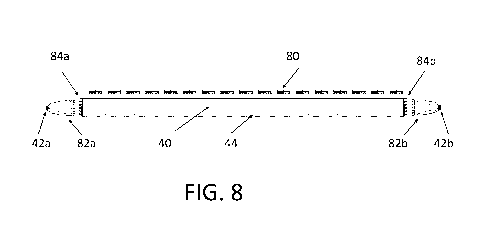
Figure 8 shows a first example of backlight design used with a 3D
autostereoscopic display.
The display comprises a lightguide 40 having light out-coupling structures 44,
and a display panel 80 over the top. The lightguide is edge illuminated, and
two light sources
42a, 42b are shown. Each light source has an associated collimator 82a, 82b.
Furthermore,
where the light output from each light source enters the edge of the
lightguide, a beam
shaping element in the form of a light in-coupling or steering arrangement
84a, 84b is
provided.
The way light is coupled into the lightguide is used to control the light
output
direction. By steering the light output, a multi-view autostereoscopic 3D
display is enabled
which utilizes the full resolution of the 2D panel 80. The light output
directions can be
altered time-sequentially so that at each time, the full resolution is used.
The display panel 80 is for example mounted with sides parallel to the side
edges of the backlight. Thus, Figure 8 shows a cross section across the
display. The light
out-coupling features 44 extend parallel to the side edges, so they control
the light output
direction in the lateral direction. The display does not need a lenticular
lens array as all
directional control is implemented by the backlight.
The display is controlled to display a sequence of multiple views. At the same
time, the directionality of the light output of a backlight is switched
between multiple
directions (corresponding to the intended viewing direction) synchronously
with switching of
the display panel.
The light out-coupling features 44 may for example comprise symmetric or
asymmetric prismatic elements, and they may be applied on the top plane or on
the bottom
plane (as shown in Figure 8) of the lightguide. A uniform out-coupling from
the lightguide
across the entire panel may be achieved in known manner. For example, the
height or density
of the structures may be tuned along the lightguide to change the relative out-
coupling of
each of the structures.
The collimators 82a, 82b ensure that the generated light is sufficiently
collimated at least in one direction (perpendicular to the light guide plane).
In the other
direction the light might be more divergent.
CA 02980487 2017-09-21
WO 2016/150778 PCT/EP2016/055614
The light out-coupling structures 44 are for example stripes raised above a
general plane, and the divergence is allowed in a plane parallel to this
general plane. Such
divergence will not change the light out-coupling function which depends on
the light
direction in a plane perpendicular to the length of the stripes, i.e. in the
plane of Figure 8.
5 The backlight unit generates light in multiple directions by
coupling the
collimated light into the lightguide under certain defined different angles.
The in-coupling of
the light can be realized in several ways, for instance by using static or
dynamically switched
optical elements situated on the side of the lightguide.
Various examples are described below.
10 The light output from the light sources requires a certain degree
of collimation.
The angular spread of light that come out of the backlight unit is determined
by the
directionality of light sources. LEDs with total internal reflection (TIR)
collimators,
reflectors, compound parabolic concentrators (CPC) or other optical elements
may be used as
a collimated light source. Alternatively, lasers may be used as the light
sources.
15 The light is collimated preferentially in one direction, namely in
the direction
perpendicular to the lightguide plane (i.e. in the plane of Figure 8) and may
diverge in
directions parallel to the lightguide plane.
The required degree of collimation depends on the application. For a portable
autostereoscopic device having two views, the angular width of one view is
about 4 degrees,
which will translate to a requirement on the collimation of a light source for
a certain design
of a lightguide. For a multi-view display higher degree of collimation may be
required.
The light angular intensity distribution produced by the backlight is
determined by a number of parameters: the light source directionality, the
beam shaping
elements determining the angles of light propagation inside the lightguide,
the refractive
index of the lightguide material, the refractive index of surrounding media,
and the geometry
of the out-coupling structures. Depending on the combination of parameters,
the light output
from the backlight unit can cover the whole 180 angular range or can be
confined in a
smaller range of angles (e.g. 0 to 90 ) from the normal. This may be achieved
by clipping
the light on one side. Using an additional light-turning optical foil (for
instance with light re-
direction prisms) then allows the clipped outgoing angular ray distribution to
be transformed
into a distribution centered around the normal direction to the backlight.
There are multiple ways to control the angular range of the light propagation
inside the light guide. One way is to confine and steer the light when it is
coupled into the
CA 02980487 2017-09-21
WO 2016/150778 PCT/EP2016/055614
16
lightguide. This control can be realized either using active optical elements,
or passive
elements placed in registration with actively switched light sources.
The functionality of the directional backlight is illustrated below by results
of
optical ray-tracing simulations of a general design comprising active beam
shaping optical
elements located at the edge of the lightguide, and an additional beam re-
direction optical
structure layer (i.e. layer 120 described below in connection with Figure 12).
The light sources are collimated in the direction perpendicular to the
lightguide plane (for example collimated to a divergence of 4 degrees or less)
and diverging
in the lightguide plane. This divergence may have any suitable value for
example between 60
degrees and 180 degrees (for example with a 90 angle).
This collimation in one plane to a much greater degree than in an orthogonal
plane gives what is termed in this document a "partially collimated" light
output.
The light sources are in-coupled via active optical elements for example
electrowetting prism elements from one side of the lightguide. The beam
shaping prism
elements in this example are considered to have the same refractive index as a
lightguide
material.
The simulation results are shown in Figure 9 and Figure 10.
Figure 9 shows the results of ray-trace simulations of beam sweeping
functionality of a backlight according to the general design. The beam output
direction is
shown on the y-axis as a function of the angle of the beam shaping prismatic
elements on the
side of a lightguide (this angle is the x-axis).
The angular intensity distribution maps for three values of the beam shaping
(in-coupling) prism apex angles of 70 , 120 and 160 are shown in Figure 10,
using the
same axes as in Figure 5.
Figure 11 shows the angular light intensity distribution of the three
simulations
of Figure 10 in a polar plot instead of using an intensity map.
The results illustrate the possibility of tuning the angles of generated views
in
the range from 70 to 110 , which correspond to angular tuning range of 20
from the
normal direction to the backlight.
At one side of the range of angular tuning (larger angles) the outgoing width
of the light is slightly broader and the view shows more distortion when the
display is tilted
in the plane perpendicular to the light guiding direction (i.e. V deviates
from 90 ). These kind
of distortions can be significantly reduced in a design when half of the views
are generated
by the light sources and optical elements situated on the different sides of a
display.
CA 02980487 2017-09-21
WO 2016/150778 PCT/EP2016/055614
17
A first embodiment will now be described in more detail, with reference to
Figure 12.
In this first embodiment, the light sources for different light output
directions
are arranged at different angles with respect to the general plane of the
lightguide, i.e.
different angles of elevation. Equivalently, they are arranged at different
angles with respect
to the edge face at which the light is coupled in to the lightguide.
Figure 12 shows a plan view and a cross sectional view and shows one set of
light sources 42a with one angle of elevation or tilt, and another set of
light sources 42b with
a different angle of elevation or tilt.
The light is in-coupled to the lightguide at different light propagation
angles,
by arranging collimated light sources at a certain angle with respect to the
in-coupling edge
of the lightguide 40. At least two different angular orientations of light
sources are provided
for example one fixed angle at one side and another fixed angle at another
side of the
lightguide. This allows for at least two main propagation directions of light
generated by the
backlight unit.
Depending on the geometry and the types of the light out-coupling structures
within the lightguide, a light re-direction film 120 may be required to
redirect the light into
the proper direction. The directions of light propagation in combination with
the light
redirection arrangement 120 will determine outgoing angles for the generated
views.
Synchronization of images displayed by a display panel with turning on/off of
the light sources of different types responsible for propagation of different
views enables a
time-sequential multi-view display to be realized.
A second embodiment will now be described in more detail, with reference to
Figure 13.
In this second embodiment, the light sources for different light output
directions have optical beam shaping elements 130a, 130b. These are static in-
coupling
structures at the sides of the lightguide. These beam shaping elements are
placed in front of
their respective light source. The elements are different in that they couple
the light into the
lightguide under a different angle. Thus, the desired tilt is implemented
optically rather than
mechanically as in the first example. By switching the light sources, input
light can be
entered with the desired angle into the lightguide and thereby steer the light
that comes out of
the lightguide.
CA 02980487 2017-09-21
WO 2016/150778
PCT/EP2016/055614
18
This directional light can again be used to create views for a time-sequential
autostereoscopic panel. The beam shaping structures used to couple the light
into the
lightguide may include either reflective (mirrors) or refractive (e.g. prisms)
optical elements.
In the example of Figure 13, the beam shaping elements comprise prismatic
structures. In this case two different types of in-coupling beam shaping
elements are defined
130a, 130b with different top angles used to couple the light into the
lightguide under
different angles.
The prismatic structures typically split incoming light into two directions.
The
angles directed downwardly with respect to the general plane of the lightguide
will couple
out of the lightguide.
The light that is coupled into the lightguide under a positive angle (upwardly
with respect to the general plane of the lightguide) can be coupled out after
it has reflected an
odd number of times inside the lightguide. Therefore, there will be only one
main direction of
the out-coupled light from each light source even though the prismatic
structures divide each
light source into two main directions.
On top of the lightguide is a prismatic light redirection arrangement 120 that
is
used to direct the out-coupled light to the normal.
The total number of main out-coupling directions Ndir that can be created with
this embodiment is given by the number of different types of beam shaping
elements used for
in-coupling of light Nin, times the number of sides at which illumination
takes place Nsides:
Ndir = Nsides x Nin
In the example shown, the total number of directions is therefore four. In
Figure 14 these directions are sketched. By time-sequentially turning on the
light sources that
correspond to one of these four directions, four different views can be
generated.
A third embodiment will now be described in more detail, with reference to
Figure 15.
In this third embodiment, the light sources for different light output
directions
include an active emitter matrix in combination with a lens. This combination
functions as a
beam steering approach which again enables the tilt or elevation angle of the
light incident to
the lightguide to be altered.
The each light source 42a, 42b comprises a light emitter matrix 150a, 150b,
and a lens 152a, 152b supported by a mechanical support 154a, 154b with a
light absorbing
structure or coating 156a, 156b.
CA 02980487 2017-09-21
WO 2016/150778 PCT/EP2016/055614
19
In this way instead of requiring multiple different optical elements, there
may
be multiple light sources per optical element. The lens will typically be a
cylindrical lens with
a focal length that approximately matches with the position of the light
sources. As a result,
the position of the light source is translated into a fan 157 that has an
angle to the lightguide
normal.
Figure 15 shows the emitter matrix 150a in more detail and shows the
individual light sources 158 such as LEDs. A line 159 of the LEDs is
associated with one
particular view direction.
Views can be scanned by selectively switching light sources. Other optical
elements such a lenticular lens array can be used to associate multiple fans
of light with a
single light source. This use of a lenticular lens creates cone repetition
which is desirable for
non-head-tracked multi-view operation.
A fourth embodiment will now be described in more detail, with reference to
Figure 16.
In this fourth embodiment, active i.e. switchable optical elements are used to
implement a similar beam steering approach, which again enables the tilt or
elevation angle
of the light incident to the lightguide to be altered.
The light sources 42a, 42b provide a collimated output which is provided to
active optical elements 160a, 160b which providing the functionality of
tunable angles of
light in-coupling into the lightguide, again relative to the general plane of
the lightguide.
These active optical elements may be based on reflective elements (e.g.
MEMS mirrors) to change light in-coupling directions or refractive elements
(e.g.
electrowetting prisms) for dynamic change of the light in-coupling directions.
When using electrowetting microprism arrays as in-coupling beam shaping
elements, the beam deflection can be quite large, theoretically reaching up to
30 , depending
on the choice of the refractive index combination of the liquids and geometry
of the
microprism cell. The active optical elements may be switched between the
different angles
with up to a kHz frequency. If the display pixel is able to operate at the
same or similar rates
it becomes possible to generate time-sequentially a large number of views in
multiple quasi-
continuous viewing directions.
The active optical elements 160a, 160b may be split into groups (for example
two groups associated with each side of a lightguide). Each group may then be
responsible
for the generation of a subset of multiple views. This allows each of the
active cells to
operate in the reduced angular range and should result in reduction of
switching time.
CA 02980487 2017-09-21
WO 2016/150778 PCT/EP2016/055614
The internal lightguide out-coupling features may have different designs.
A first set of examples is based on total internal reflection. They re-direct
the
light to the front plane by total internal reflection (TIR), where the light
is extracted out of the
lightguide.
5 In order to maximize the angular range of rays extracted from the
lightguide
the preferred angle 0 at the base of the prism (i.e. the angle of the
reflecting facet with respect
to the general plane of the lightguide) should obey the relation:
cos (2P) = 1/nig
where nig is the refractive index of the material of the lightguide (for the
10 prismatic recess in contact with air). More generally this condition
transforms to:
cos (2P) = no/nig,
when the light out-coupling structure is in contact with another medium with
refractive index no.
This maximizes the angular range of rays which can be extracted from the
15 lightguide. If 0 =0 (no extraction structures), light will not be
extracted at all, for an
intermediate values of 0 (i.e. cos (2P) > no/mg), the light distribution out
of the lightguide will
have some intermediate width, and for 0 = {cos-1(no/nig)}/2 the width of the
angular
distribution which can be extracted is about 90 degrees, as shown in Figure 6.
A second set of examples is based on the extraction features which have a
20 reflecting surface (i.e. regardless of the angle of incidence). The
light out-coupling structures
at the backplane of the lightguide are for example coated with a light
reflective coating (e.g.
metal). Because there is no longer the constraint that total internal
reflection is needed at the
out-coupling structure, it is possible to select from a broader range of
angles 0 (the base of
the out-coupling prism).
The maximum width of the out-coupled light as a function of 0 has been
calculated and the result is shown in Figure 17, which plots the light output
width (y-axis)
against the prism base angle 0 (x-axis). In order to maximize the angular
width of the
outgoing light 0 can be selected to be:
sin-l[namb/nig] < 13 < (90 -sin-l[namb/nig]
For PMMA this amounts to a value of 0 between 42 and 48 degrees. For these
values of J3, the out-coupled light can be in the range of -90 degrees up to
90 degrees,
depending on the direction of the in-coupled light.
With the lightguide made of PMMA material (n=1.48) and out-coupling
structures based on prismatic grooves where light re-direction occurs via
total internal
CA 02980487 2017-09-21
WO 2016/150778 PCT/EP2016/055614
21
reflection, the apex angle of the internal light out-coupling prisms will be
optimized at 132
degrees (so that 0 =44 degrees) to satisfy the condition of cos (2P) = 1/n as
outlined above.
Figure 17 is for a lightguide made out of PMMA in air. There is a small range
of 0 for which the cone width is maximal at 180 degrees.
Some examples above make use of a light redirection arrangement in the form
of a redirection film 120 over the lightguide. This is needed for example if
the (direct) light
output from the backlight unit is confined in a range of angles (e.g. 00 to 90
) from the
normal. This is the case if the output light is clipped on one side. This
angular light
distribution may be transformed into a distribution which is centered around
the normal
direction, which enable the directional backlight unit to be applied more
straightforwardly to
multi-view displays.
An additional optical film comprising structures for re-direction of light
towards the normal direction is placed on the top of the lightguide. The
structures may be
prismatic elements with an apex angle which can be chosen based on the
refractive index of
the material (for instance around 55 for PMMA), and are oriented towards the
lightguide.
Compared to the examples of out-coupling structure with a reflector coating,
the prismatic groove light out-coupling structures in the lightguide in the
examples based on
total internal reflection case can have smaller base angle. As a result, the
out-coupling
structures are flatter and can be easier to manufacture.
Adding re-direction prisms on the top of the lightguide allows the outgoing
angular ray distribution to be converted into the distribution centered around
the normal
direction to the backlight. An optimum apex angle of 55 degrees achieves this
redirection.
With this design, by tuning the angles of prisms on the side of the
lightguide, the outgoing
beam can for example be scanned in the range 20 from the normal. This
relationship
between the prism angle and the beam direction is shown in Figure 9 discussed
above, and it
shows the output beam direction being adjustable in the approximate range 90
20 degrees.
A fifth embodiment will now be described in more detail, with reference to
Figure 18.
In this fifth embodiment active optical elements are used in combination with
a switchable light source in order to mask view transitions.
A possible disadvantage of some implementations of active optical elements is
the time that is required to switch between any two optical modes. During this
transition,
light sources should be turned off to avoid visible ghosting or a mediocre
black level. The
CA 02980487 2017-09-21
WO 2016/150778 PCT/EP2016/055614
22
switching time of the optical elements may result in a low view count or
perceptible flicker
and low brightness.
The switching time can be hidden by a scanning backlight approach where a
number of light source and optical element combinations act in synchronism to
enable a
flicker free operation. Each combination is in either a "transition" or an
"on" state.
The example of Figure 18 has a backlight with four sub-frames shown
sequentially in Figure 18(a) to 18(d). In each sub-frame two views or modes
"A" and "B" are
active. Modes "A" and "B" could for instance correspond to the left and the
right eye of a
single viewer or to viewer "A" and "B". Different views may correspond to a
different
viewpoint in each frame.
The labels ON or OFF denote whether a light source is on or off Each light
source presents its output to a collimator and then a steerable optics system.
Each light source
follows a sequence of Mode A (light source ON), Switching to Mode B (light
source OFF),
Mode B (light source ON), Switching to Mode A (light source OFF). In this way,
light
sources are only on when the beam steering system is ready, and by staggering
the light
sources there is no discontinuity.
This arrangement enables a reduction in flicker.
In the system of Figure 18 the light of the "Mode A" and "Mode B" light
sources is arranged not to mix. This can be achieved by partial collimation of
the light
sources in the plane of the lightguide, or there could be multiple lightguide
strips such that
light is confined within the strips by total internal reflection on the strip
side walls.
A perfectly collimated backlight unit will have the same light output
direction
from all the areas of the backlight. When the angular light distribution of a
backlight is
sufficiently narrow, such that it is smaller than the field of view of a
display, this can create
an unwanted effect that light from not all the areas of a display can reach
the eyes of the
observer (some parts of a display will appear dark).
For common lenticular-based autostereoscopic displays, this so-called
viewpoint correction is realized by a mismatch between the pitch of display
sub-pixels and
lenticular lens pitch. In this way, light from the pixels at the sides of a
display is directed at
different directions with respect to light from the center of the display
panel. For a directional
backlight unit this correction of an angular distribution can be realized
either at the level of a
re-direction optical foil or (if no foil is used) at the level of the light
out-coupling structures
within the lightguide. The correction requires spatially selective adjustments
of structure
CA 02980487 2017-09-21
WO 2016/150778 PCT/EP2016/055614
23
geometries (angle of redirection prisms or other light out-coupling
structures) along the
length of the backlight.
The purpose is to ensure that the light output angles from the top face of the
backlight (which may or may not include a light redirection film) vary as a
function of
position over the top face such that light reaches a common view point from
all positions of
the top face. This common view point will be different for the two modes of
the backlight,
but it will be at the same distance from the display, so that one viewpoint is
the expected
location of one eye of a user and the other view point is the expected
location of the other eye
of the user.
For the range of display dimensions, a typical field of view is within 7-12
degrees (half angle). Optical simulations have been performed for a design,
where the
angular distribution correction is realized at the level of the light re-
direction film. The angles
of prismatic structures are modified as a function of their distance from the
center line of the
backlight. The angular correction of the outgoing light direction at the sides
of a backlight
was chosen to be 100 (light is tilted towards the viewer).
The beam-sweeping functionality of a backlight for this design with a
modified light re-direction plate was checked by optical modeling to be in the
same range as
presented in Figures 9 to 11. It has been verified that the light rays from
the sides and the
center of a backlight converge into the same viewing region, providing an
effective viewpoint
correction for the whole angular tuning range of the backlight ( 20 ).
Some display systems make use of head-tracking of viewer position. In such a
system, driving of active optical elements can be adjusted to generate views
at a specific
direction for best comfort for the specific viewer position (or multiple
viewers).
The directional backlight component can be applied to autostereoscopic multi-
view 3D displays, and for displays with privacy mode.
Other variations to the disclosed embodiments can be understood and effected
by those skilled in the art in practicing the claimed invention, from a study
of the drawings,
the disclosure, and the appended claims. In the claims, the word "comprising"
does not
exclude other elements or steps, and the indefinite article "a" or "an" does
not exclude a
plurality. The mere fact that certain measures are recited in mutually
different dependent
claims does not indicate that a combination of these measures cannot be used
to advantage.
Any reference signs in the claims should not be construed as limiting the
scope.