Note : Les descriptions sont présentées dans la langue officielle dans laquelle elles ont été soumises.
CA 02980686 2017-09-22
WO 2016/151504
PCT/1B2016/051640
METHOD AND SYSTEM FOR OPTIMIZING MOVEMENT OF PRODUCTS USING
ROBOTIC DRIVE UNITS (RDUS) IN A WAREHOUSE ENVIRONMENT
[0001] The present subject matter relates, in general, to optimizing
movement of
robotic drive units (RDUs) and, in particular, to optimizing movement of
products using
RDUs in a warehouse environment.
BACKGROUND
[0002] Robotic drive units (RDUs) are mobile robotic systems having
wheels, motors,
guidance sensors, and communication capabilities. The RDUs are used in a wide
variety of
applications, typically, for storage and retrieval of products. For example,
RDUs are used in
warehouses, where a huge number of products of various types are stored in,
for example
racks, shelves, and compartments, for retrieving and storing the products,
thereby fulling
orders.
BRIEF DESCRIPTION OF DRAWINGS
[0003] The features, aspects, and advantages of the present subject
matter will be better
understood with regard to the following description, and accompanying figures.
The use of
the same reference number in different figures indicates similar or identical
features and
components.
[0004] Fig. 1 illustrates a block diagram representation of robotic
drive unit (RDU), in
accordance with an implementation of the present subject matter.
[0005] Fig. 2(a) illustrates an RDU, in accordance with an implementation
of the
present subject matter.
[0006] Fig. 2(b) illustrates a rotary plate in an RDU, in accordance
with an
implementation of the present subject matter.
[0007] Fig. 3 illustrates a three dimensional view of an RDU, in
accordance with an
implementation of the present subject matter.
[0008] Fig. 4(a) illustrates vertical movement of an arm holder of an
arm unit, in
accordance with an implementation of the present subject matter.
[0009] Fig. 4(b) illustrates horizontal movement of arms of RDU, in
accordance with
an implementation of the present subject matter.
[0010] Fig. 5 illustrates navigation of an RDU, in accordance with an
implementation
of the present subject matter.
1
CA 02980686 2017-09-22
WO 2016/151504
PCT/1B2016/051640
[0011] Fig. 6 illustrates an example warehouse in which multiple RDUs
are used for
storage and retrieval operations, in accordance with an implementation of the
present subject
matter.
[0012] Fig. 7 illustrates a schematic representation of a network
environment of a
warehouse, in accordance with an implementation of the present subject matter.
[0013] Fig. 8 illustrate a method 800 utilized by a computing system
for optimizing a
retrieval operation, in accordance with an implementation of the present
subject matter.
[0014] Fig. 9 illustrates a network environment 900, in accordance
withan
implementation of the present subject matter.
[0015] Fig. 10 illustratesa method 1000 for utilizing a robotic drive unit
(RDU) to
deliver a plurality of products to a destination location,in accordance withan
implementation
of the present subject matter.
DETAILED DESCRIPTION
[0016] The present subject matter relatesto systems and methods for
optimizing
movement of robotic drive units (RDUs).
[0017] RDUs are robot based systems that are typically used formoving
inventory. An
RDU can include at least one motor for moving the RDU, at least one arm
controlled by the
motor for carrying a product or its container, and guidance sensors coupled to
the motor for
assisting with the movement of the RDU. The RDU can be equipped with
communication
capabilities that enable the RDU to be controlled remotely.
[0018] The RDUs have found widespread acceptance in warehouses, where
thousands
of different products may be stored in different sections in, for example,
racks, shelves, and
the like, for storing and retrieving products. An RDU may be controlled by,
for example, a
computing system, which can provide instructions to the RDU for retrieving or
storing a
product. The instructions may be provided by the server in response to an
order for which
multiple products in disparate locations of the warehouse are to be retrieved
or for which
multiple products have to be stored in disparate locations of the warehouse.
In response to the
instructions, the RDU may then go to each location, retrieve the products (in
the case of
retrieval), collect them, and deliver them in a location to be delivered.
Therefore, for catering
to a single order, the RDU may have to travel to multiple locations inside the
warehouse,
which leads to a reduction in the speed of retrieval or storage and also
reduction in cost
efficiency.
2
CA 02980686 2017-09-22
WO 2016/151504
PCT/1B2016/051640
[0019] Further, a typical warehouse environment can have multiple RDUs
to cater to
multiple storage and retrieval orders simultaneously. As explained earlier,
each RDU may
have to go to multiple locations for retrieving or storing products
corresponding to the order
they fulfill.At times, multiple RDUs may be at a same location in the
warehouse for
retrieving products that are placed near each other. Similarly, multiple RDUs
may be at a
same location in the warehouse for storing products. Thus, traffic at the
location may
increase, leading to a further decrease in the storage or retrieval speed and
throughput of the
storage and retrieval operations.
[0020] The present subject matter relates to systems and methods for
optimizing
movement of RDUs. With the methods and systems of the present subject
matter,speed of
storage and retrieval of products by the RDUs can be significantly improved.
[0021] In an implementation of the present subject matter, an order
for a plurality of
products to be retrieved from a warehouse is received. The warehouse has a
plurality of
RDUs for fulfilling the order. A first RDU of the plurality of RDUs is
assigned a task of
delivery of the plurality of products to a destination location. Then, an
analysis is performed
for each product of the plurality of products whether retrieval of product is
to be assigned to
an RDU other than the first RDU. The analysis is performed based on one or
more
conditions. Thereafter a task of retrieval of one or more products is assigned
to one or more
RDUs other than the first RDU based on the analysis. Further, an intersection
point between a
future path of the first RDU and a future path of each of the one or more RDUs
is determined.
Based on the determination, each RDU of the one or more RDUs is instructed to
deliver
respective retrieved products at the intersection point between its future
path and the future
path of the first RDU. In addition, the first RDU is instructed to retrieve
each product of the
one or more products delivered at each intersection point for delivering at
the destination
location.
[0022] Since retrieval of the one or more products is assigned to the
one or more RDUs,
the first RDU is freed of the task of going to a location of each of the one
or more products.
Thus, the travel time of the first RDU is significantly reduced. Further, the
order is fulfilled at
a faster rate. Further, since the first RDU does not have to travel to the
locations of each of
the one or more products, traffic at the locations of the one or more products
is reduced.
[0023] The above and other features, aspects, and advantages of the
subject matter will
be better explained with regard to the following description, appended claims,
and
accompanying figures.
3
CA 02980686 2017-09-22
WO 2016/151504
PCT/1B2016/051640
[0024] The above mentioned methods and systems are further described
with reference
to figures. It should be noted that the description and figures merely
illustrate the principles
of the present subject matter along with examples described herein and, should
not be
construed as a limitation to the present subject matter. It is thus understood
that various
arrangements may be devised that, although not explicitly described or shown
herein,
embody the principles of the present disclosure. Moreover, all statements
herein reciting
principles, aspects, and examples thereof, are intended to encompass
equivalents thereof.
Further, for the sake of simplicity, and without limitation, the same numbers
are used
throughout the drawings to reference like features and components.
[0025] Fig. 1 illustrates a block diagram representation of robotic drive
unit (RDU)
100, in accordance with an implementation of the present subject matter. The
RDU 100
includes, among other components, processor(s) 102, a drive unit 104, an arm
unit 106,
product sensors 108, an obstacle detection unit 110, a vision guidance and
navigation unit
112, a communication device 114, and I/0 (input/output) device 116.
[0026] The processor(s) 102 may be implemented as microprocessors,
microcomputers,
microcontrollers, digital signal processors, central processing units, state
machines, logic
circuitries, and/or any devices that manipulate signals based on operational
instructions.
Among other capabilities, the processor(s) 102 may fetch and execute computer-
readable
instructions stored in a memory. The functions of the processor(s) 102 may be
provided
through the use of dedicated hardware as well as hardware capable of executing
machine
readable instructions. The processor(s) 102 operates the RDU 100 based on
commands or
instructions received from a computing system (not shown in Fig.) and inputs
received from
the product sensors 108, the obstacle detection unit 110, and the vision
guidance and
navigation unit 112.
[0027] The drive unit 104 moves the RDU 100 to various locations in a
warehouse
based on commands received by the processor(s)102. The drive unit 104
includes, at a
minimum, a motor, a drive wheel and one or more caster wheels. Here, a
warehouse refers to
any location in which multiple products are stored in various locations and
where products
are required to be stored and retrieved.
[0028] The arm unit 106 includes at least one arm to hold a product and an
arm holder
to hold the at least one arm. Here, a product may refer to a product and a
container in which
the product is kept.
[0029] The product sensors 108 are used to recognize products that are
be stored or
retrieved. The recognition can be performed to verify whether a correct
product has been
4
CA 02980686 2017-09-22
WO 2016/151504
PCT/1B2016/051640
stored or retrieved. The product sensors 108 can include, but are not
restricted to, barcode
readers, RFID scanners, and cameras.
[0030] The obstacle detection unit 110 determines whether an object is
in a travel path
of the RDU 100. If an object is determined to be in the travel path of the RDU
100, the
obstacle detection unit 110 can communicate to the processor(s) 102. The
obstacle detection
unit 110 can include an imaging device, such as a camera, or an ultrasonic
sensor. In an
implementation, the obstacle detection unit 110 generates a new travel path
for the RDU 100.
[0031] The vision guidance and navigation unit 112 enables the RDU 100
to navigate
through the warehouse. The vision guidance and navigation unit 112 enables the
navigation
by scanning features present in the warehouse. The features can include, but
are not restricted
to, objects, text, symbols, codes, stickers, and patterns, on, for example,
the floor, the wall, or
the ceiling of the warehouse. In an implementation, the vision guidance and
navigation unit
112 can include a camera which can capture the landmarks. The landmark
information may
then be communicated to the processor 102 for determining a direction for
navigation. The
vision guidance and navigation unit 112 can also include a global positioning
system (GPS)
that captures accurate three dimensional location. In an implementation, the
vision guidance
and navigation unit 112 determines the location of the RDU 100 based on
surroundings of the
RDU 100, such as inventory racks, storage units, and last storage unit at
which an action has
been executed. The navigation of the RDU 100 will be explained in greater
detail with
reference to Fig. 5.
[0032] The communication device 114 communicates with the computing
device for
receiving information, such as a task, and sending information, such as
position of the RDU
100,amount of inventory on the RDU 100, and completion of a task by the RDU
100. In an
implementation, the communication device 114 is a wireless communication
device with Wi-
Fi functionality.
[0033] The I/0 device 116 includes an input device, such as a keyboard
and a touch
sensitive display, which facilitates a user to interface with the RDU 100. The
I/0 device 116
can also include a display to display information related to ongoing tasks and
actions,
pending tasks, and other information related to the RDU 100.
[0034] Fig. 2(a) illustrates an RDU 200, in accordance with an
implementation of the
present subject matter. The RDU 200 may be similar to the RDU 100. The RDU 200
includes
an arm positioner 202 that adjusts position of an arm unit 204 in a vertical
plane. The arm
positioner 202 enables the arm unit 204 to be moved along arm supporting
structure 206, as
illustrated by two thick arrows pointing upwards and downwards, for
positioning the arm
5
CA 02980686 2017-09-22
WO 2016/151504
PCT/1B2016/051640
holder 204 in the vertical plane.In an example, the arm positioner 202 can
position the arm
unit 204 near a shelf in an inventory rack, which enables storing or
retrieving products in the
shelf.
[0035] As illustrated in Fig. 2(a), the arm positioner 202 can include
a motor which is
coupled to the arm unit 204 through pulley 207 and another pulley at the top
of the RDU 200
(not shown in Fig.).The arm positioner 202 can be mounted on chassis 208 of
the RDU 200.
[0036] The arm unit 204 includes an arm that further includes a base
arm 210 and an
extendable arm 212, which is housed in the base arm 210.The extendable arm 212
can be
extendedand retracted, as illustrated by two thick horizontal arrows, which
enables retrieving
and storing the products, for example, in the shelf of in the inventory rack.
When extended,
the extendable arm 212 extends beyond the chassis 208 of the RDU 200. The
extendable arm
212 can include holders for firmly holdingand lifting the products. The
extension and
retraction of the extendable arm 212 from the base arm 210 can be controlled
using an arm
extender 214. The operation of the arm extender 214 will be explained in
greater detail with
reference to Fig. 3.
[0037] In an implementation, the arm supporting structure 206 is
rotatable 360 relative
to the chassis 208. The rotation of the supporting structure 206enables
horizontally
positioningthe arm for storing and retrieving the products without rotating
the entire RDU
200. The rotation of the supporting structure is illustrated in Fig. 2(b).
[0038] As illustrated in Fig. 2(b), the RDU 200 can include a rotary plate
213 on which
inventory to be rotated for storing in a location is placed, and rotated by a
motor (not shown
in Fig.),In another implementation, the extendable arm 212 can traverse behind
the arm
supporting structure 206 in the horizontal plane to reach inventory racks
behind the arm
supporting structure 206.In an implementation, the traversal behind the arm
supporting
structure 206 can be effected by rotating the arm unit 204 which can be
rotated by 360
relative to the arm supporting structure 206. In another implementation, the
traversal can be
effected by retracting the extendable arm 212 such that it extends behind the
arm supporting
structure 206.
[0039] Referring back to Fig. 2(a), the RDU 200 traverses along the
warehouse using a
drive wheel 216. The drive wheel 216 may be powered by a drive unit, similar
to the drive
unit 104, which, in turn,can be controlled by a processor (not shown in Fig.),
which is similar
to the processor(s) 102. The processor can be placed near the chassis 208. In
addition to the
processor, the RDU 200 can include an additional processor (not shown in Fig.)
on its top.
The additional processor can be utilized for communication with the computing
system. The
6
CA 02980686 2017-09-22
WO 2016/151504
PCT/1B2016/051640
drive whee1216 can be balanced and supported by one or more caster wheels,
such as caster
wheels 218-1 and 218-2.
[0040] The RDU 200 includes a storage space in which plurality of
products can be
carried. In an implementation, the storage space includes one or more
compartments 220-1,
__ 220-2...., 220-N,in which products, such as products222-1 and 222-2can be
accommodated
for their storage and retrieval. The storage space can be divided into the
compartments 220-1,
220-2, 220-3, and 220-4 by dividers 224-1, 224-2... and 224-N. Although the
RDU 200 is
shown as havingseven compartments, it will be understood that the RDU 200 can
have more
or fewer compartments.
[0041] The presence of multiple compartments in the RDU 200 enables storing
multiple
products in the RDU 200 for fulfilling orders. In an example order for which
five products
have to be retrieved, all products can be retrieved by the RDU 200 and
delivered to
warehouse personnel in a single shot, unlike a conventional RDU having a
single
compartment, which performs retrieval and delivery actions five times, one for
each product.
__ Thus, using the RDUs of the present subject matter, storage and retrieval
operations are
considerably faster. The multiple compartments may be offset to be parallel to
the axis of the
arm vertical movement in case of rotatable arm unit 204 or rotatable
supporting structure 206.
[0042] In an implementation, the RDU 200rearranges the products 222
among the
compartments 220. The rearrangement can be performed to enable storing a
product retrieved
__ from a shelf in the inventory rack. For example, if a product is to be
retrieved from a shelf
that is at a height of the compartment 220-1, and the compartment 220-1 is
occupied with the
product 222-1, the RDU 200 can relocate the product 220-1 to another
compartment, say
compartment 220-2, which is vacant.The RDU 200 can then retrieve the product
to be
retrieved from the shelf and store it in the compartment 220-1. The manner in
which the
__ rearrangement is performed will be explained in detail with reference to
Fig. 3.The
rearrangement of the products in the RDU 200 enables the RDU 200 to collect
multiple
products before reaching a destination location for delivery of the products.
This is because,
if multiple products which are in shelves at the same height are to be
retrieved for an order,
the RDU 200 can rearrange products in its compartments to retrieve all the
products. In case
__ of a rotatable arm unit 204 or rotatable arm supporting structure 206, the
products can be
directly relocated to another compartment without removing the existing
inventory item in a
compartment.
[0043] Fig. 3 illustrates a three dimensional view of anRDU 300, in
accordance with an
implementation of the present subject matter. The RDU 300 may be similar to
the RDU 100
7
CA 02980686 2017-09-22
WO 2016/151504
PCT/1B2016/051640
and the RDU 200. The RDU 300 includes two arms. One arm includes extendable
arm302
and another arm includes extendable arm 304 (parallel to the extendable arm
304 on other
side of the RDU 300), similar to the extendable arm 212, which are extendable
in the
direction shown by arrows 306 to store and retrieve products, such as product
308, in a shelf
of an inventory rack. Further,the two arms, of arm unit 310 (similar to the
arm unit 204),can
be moved horizontally in the direction shown by arrows 312 for holding the
products of
different shapes and sizes. The movement in the direction of arrows 312 can be
effected using
a horizontal arm positioner (not shown in Fig.) The horizontal arm positioner
is explained
with reference to Fig. 4(b).
[0044] Similarly, vertical movement in a direction 314 of the arm unit
310to retrieve
the product from different levels of shelves is achieved using arm
positioner316, similar to
the arm positioner 202.
[0045] The vertical movement in the direction 314 can be used for
rearranging products
among compartments in the RDU 300.In an implementation, the rearrangement of a
product
among compartments can be performed by bringing the arm unit 310to the level
of the
compartment from which a product is to be relocated, holding the product using
holders 318
of the extendable arms 302 and 304, extending the extendable arms 302 and 304,
moving the
arm unit 310 in the direction 312 towards a vacant compartment to which the
product is to be
relocated, retracting the extendable arms302 and 304 once the arm unit 310
reaches the level
of the vacant compartment, and finally, loosening the holders 318, so that the
product can be
placed on the vacant compartment. Although the rearrangement is explained in
an
implementation where the RDU 300 includes multiple compartments, however, the
rearrangement is possible in an implementation of the RDU 300 without the
multiple
compartments. In accordance with the implementation, multiple products are
stacked on top
of each other, which are relocated by the arm unit 310.
[0046] The extension and retracting of the extendable arms302 and 304
enable vertical
movement of a product in the RDU 300 without disturbance to the
compartments.In an
implementation, the extension and retraction is achieved using an arm extender
320, similar
to the arm extender 214. The arm extender 320 includes a motor 322 and a
pulley 324 that is
coupled the shaft of the motor 322. The pulley 324 is further coupled to
pulley 326 through a
belt (not shown in Fig.). The rotation of the motor 322 is translated to the
extension and
retraction motion of the extendable arms 302 and 304 by the pulleys 324 and
326.
[0047] Fig. 4(a) illustrates vertical movement of an arm holder 402 of
an arm unit, in
accordance with an implementation of the present subject matter. The arm
holder 402 is used
8
CA 02980686 2017-09-22
WO 2016/151504
PCT/1B2016/051640
to hold a base arm similar to the base arm 210. As illustrated, the arm holder
402 is coupled
to a motor shaft 404. The rotation of the motor shaft 404 translates into a
linear motion of the
arm holder 402 in an upward and downward direction along an arm supporting
structure 406.
In an implementation, the translation of the rotary motion to the linear
motion can be effected
by means of a ball screw mechanism 408. In other implementations, the
translation can be
effected by means of pulleys, gears, or a rack and pinion arrangement.
[0048] Fig. 4(b) illustrates horizontal movement of arms of an RDU
using horizontal
arm positioner, in accordance with an implementation of the present subject
matter. A
horizontal arm positioner 410 includes a slider coupling to enable extendable
arms 412 and
414 to extend forward or backward towards the product or container. In other
words, the
horizontal arm positioner 410 enables the extendable arms 412 and 414 to move
towards and
away from each other. The slideable movement of the extended arms is
represented by
arrows 412.
[0049] The RDUs can navigate in a warehouse for various storage and
retrieval
operations. The navigation of an RDU will now be explained in greater detail
with reference
to Fig. 5.
[0050] Fig. 5 illustrates navigation of an RDU 500, in accordance with
an
implementation of the present subject matter. For assisting the navigation of
the RDU 500,
the floor or the warehouse includes a plurality of stickers 502-1, 502-
2.....502-N. The
plurality of stickers forms part of the features, which were explained with
reference to the
description of Fig. 1. To scan the plurality of stickers, the RDU 500 includes
a sensor, such as
a camera 504. Instead of a camera, the sensor can be a laser positioner, a
sound signal
positioner, or data transmission positioners, which helpsthe RDU 500 to locate
itself in a
warehouse.As explained earlier, the scanned information can be sent to the
processor of the
RDU 500 by a vehicle guidance and navigation unit, similar to the vehicle
guidance and
navigation unit 112. Based on the received scanned information, the processor
can determine
a direction to move in. The processor can determine the direction to move in
based on
instructions received from the computing system. The instructions received
from the
computing system can be based on the number of stickers scanned. For example,
the
instructions can be "travel straight until 10 stickers are scanned, then take
a right and travel
straight till 20 stickers are scanned, and then travel left for 5 stickers".
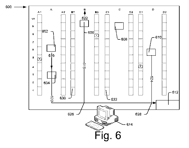
[0051] Fig. 6 illustrates an example warehouse 600 in which multiple
RDUs are used
for storage and retrieval operations, in accordance with an implementation of
the present
subject matter. The warehouse 600 includes multiple inventory racks Al, A2,
Bl, B2, Cl,
9
CA 02980686 2017-09-22
WO 2016/151504
PCT/1B2016/051640
C2, D1, and D2. The inventory racks A1-D2 include multiple storage levels,
each of which
includes multiple shelves (not shown in the Fig.) for storage of products.
Each inventory rack
is divided into storage units 1 to 10 for identification of a product
location. For performing
the storage and retrieval operations in response to an order, multiple RDUs,
RDUs 602, 604,
606, 608, and 610, are utilized in the warehouse 600. Although the warehouse
600 is shown
to have five RDUs, it will be understood that the warehouse 600 can include
any number of
RDUs. The warehouse 600 may include a destination location 612 where warehouse
personnel can receiveretrieved products from the RDUs 602-610, or can provide
products to
the RDUs 602-610 for storage in the warehouse 600. The destination location
612 may also
be a location outside the warehouse 600. The warehouse 600 may also include a
plurality of
destination locations.
[0052] For controlling the RDUs 602-610 for the storage and retrieval
operations, a
computing system614 is utilized. The computing system 614 includes
processor(s), an order
receiving module, an RDU assignment module, and an intersection point module
(not shown
in Fig.).
[0053] The computing system 614 accepts ordersrelated to storage and
retrieval
operations from an authorized user and performs one or more operations
accordingly. The
authorized user may be warehouse personnel. To fulfill the order using the
RDUs 602-610,
the computing system 614 stores warehouse inventory location data, which can
include, but is
not restricted to, product details, such as product identification number,
product name, brand,
and quantity, storage information of a product, such as product container
identifier (ID),
storage unit number, storage level, shelf ID, and inventory rack ID, and
location information
of the product. The computing system 614 communicates with the RDUs 602-610
using any
known communication technology, such as Wi-Fi, to assign tasks and to keep
track of
execution of tasks.
[0054] The warehouse 600 may have multiple products stored at
different locations.
When an order for products is retrieved by the computing system 614, the
products
corresponding to the order are to be retrieved from the locations they are
stored in. For this,
the computing system 614 assigns the order as a task to an RDU, which then
executes the
assigned task. The task includes multiple actions, which can include, but are
not restricted
to,navigating to a shelf in the warehouse 600 at which a product to be
retrieved is stored and
retrieving the product from the shelf. Further, the task includes information
about the product
to be retrieved, which can include, but is not restricted to, product name,
product ID, ID of a
CA 02980686 2017-09-22
WO 2016/151504
PCT/1B2016/051640
container that carries the product, storage unit number, storage level number,
inventory rack
ID.
[0055] In addition to the above information, to enable the RDU to
navigate to the shelf
in in which the product to be retrieved is stored, the computing system 614
communicates
location information of the shelf to the RDU. The location information is sent
as part of the
task. In an implementation, the computing system 614 can communicate the
location
information as three dimensional coordinates of the shelf. In another
implementation, the
computing system 614 can send the location information as instructions
explained in the
description of Fig. 5. The manner in which the computing system 614
communicates the
location information can be based on capabilities of vision guidance and
navigation unit of
the RDU. For example, if the vision guidance and navigation unit includes a
GPS, which can
navigate based on received three dimensional location information, the
computing system
614 communicates the location information in the form of three dimensional
coordinates of
the shelf. Similarly, if the RDU includes a camera similar to the camera
similar to the camera
504, the computing system 614 can send instructions in the form of number of
stickers to be
scanned in each direction. In an implementation, the location information
includes
checkpoints en route to the product and a destination point.
[0056] For retrieving products from multiple locations in the
warehouse 600 or for
storing products to multiple locations, the computing system 614 can optimize
the movement
of the RDUs in such a way that the total time taken for completing the storage
or retrieval
operation is reduced. The optimization by the computing system 614 will now be
explained
with the help of an example scenario in which three products, products X, Y,
and Z, have to
be retrieved from three different locations in the warehouse 600 and then
delivered to the
destination point 612. Although the example scenario is explained with the
help of retrieval
of three products, it will be understood that the optimization can be extended
to retrieval of a
plurality of products.
[0057] In accordance with the example scenario, initially, the
computing system 614
identifies the locations of all the RDUs 602-610 in the warehouse 600. The
identification of
the location can be performed using, for example, information received from a
vehicle
guidance and navigation unit, such as the vehicle guidance and navigation unit
112, in the
RDUs 602-610.The information can be received from the RDUs by the RDU
communication
module.
[0058] Then, the order receiving module receives an order for which
three products,
products X, Y, and Z, are to be retrieved from the warehouse 600.
11
CA 02980686 2017-09-22
WO 2016/151504
PCT/1B2016/051640
[0059] Thereafter, the RDU assignment module assigns a task of
delivery of the three
products, products X, Y, and Z, to the first RDU 602. As explained earlier,
the tasks assigned
by the computing system 614 includes actions to be performed by the first RDU
602. In
accordance with this example, the actions include the following:
Action 1: retrieve the product X from storage unit 5 of inventory rack Al,
Action 2: retrieve the product Y from storage unit 8 of inventory rack B2, and
Action 3: retrieve the product Z from the storage unit 4 of inventory rack Dl.
[0060] In addition to the action information, the task includes the
shelf and inventory
rack information for the products X, Y, and Z.Further, task also includes the
location
informationof the shelves in which the products X, Y, and Z are stored are
also
communicated to the first RDU 602by the computing device 614.Here, a single
storage level,
i.e., one shelf per storage unit is shown for simplifying the illustration.
However, the each
storage unit can include multiple storage levels, i.e., multiple shelves.
Accordingly, the
storage level information can be specified in the action.
[0061] Upon the assignment of the task to the first RDU 602, the RDU
assignment
moduleanalyzes, for each of the three products, whether retrieval of the
product is to be
performed by an RDU other than the first RDU 602. In other words, the RDU
assignment
module analyzes for each of the products X, Y, and Z whether retrieval of the
product is to be
performed by any of the RDUs 604-610.For the analysis, the RDU assignment
module
utilizes one or more conditions. In an implementation, the one or more
conditions include,
but are not restricted to, distance of an RDU other than the first RDU 602
(RDUs 604-610)
from each product, availability of vacant compartments in the RDU other than
the first RDU,
future path of the RDU other than the first RDU, and vacancy of a shelf
nearest to the
intersection point of the first RDU 602 and the RDU other than the first RDU.
[0062] The one or more conditions will now be explained in greater detail.
Regarding
the first condition, i.e., the distance of an RDU other than the first RDU
from each product,
the RDU assignment module compares the distance of the first RDU 602 from each
product
to be retrieved with distance of other RDUs (604-610) from the product. For
example, the
RDU assignment module compares the distance of first RDU 602 from the product
X with
the distance of other RDUs 604-610 from the product X. If the first RDU 602 is
found closer
to the product than any other RDU, the RDU assignment module 614 determines
that first
RDU 602can be used retrieve the product. For example, since first RDU 602 is
closest to the
product X, the RDU assignment module can determine that first RDU 602 has to
retrieve the
12
CA 02980686 2017-09-22
WO 2016/151504
PCT/1B2016/051640
product X. However, if the RDU assignment moduledetermines that an RDU other
than first
RDU 602 is closer to a product, the RDU assignment module can consider the
other RDU for
the retrieval. For example, when the RDU assignment module performs the
distance
calculations for the product Y, it determines that RDU 606 is closest to the
product Y.
Similarly, the computing system 614 determines that RDU 610 is nearest to the
product Z.
[0063] Regarding the second of the one or more conditions
(availability of vacant
compartments in the RDU other than the first RDU), the RDU assignment module
determines
if an RDU other than the first RDU 602 has a vacant compartment or not. If the
RDU is
found to have a vacant compartment, the RDU assignment module considers the
RDU for the
task of retrieval of the product.
[0064] Regarding the third condition (future path of the RDU other
than the first
RDU)the RDU assignment module analyzes future path of each RDU. Every RDU in
the
warehouse 600 has its own task of delivery assigned to it. In other words,
each RDU has the
task of delivering some products to a destination location. The destination
location for an
RDU can be same as, or different from the destination location 612. For this,
the RDU can
take a path to the destination location. The path taken by the RDU 606 is
illustrated by the
dotted line 618, which extends from the RDU 606 to the destination location
612. For an
RDU to be able to retrieve a product to be delivered by the first RDU 602, a
future path, i.e.,
a path to be taken by an RDU to reach the destination location 612, of that
RDU and the first
RDU 602 have to coincide. For example, the future path of the RDU 606 is 618,
which
coincides the future path 620 of the first RDU 602. If, however, the future
path of the RDU
606 was starts in the direction as indicated by the arrow 622, the future path
of the RDU 606
may not coincide with the future path of the first RDU 602. Thus, the RDU
assignment
module considers an RDU for retrieving a product to the delivered by the first
RDU 602 if its
future path coincides with that of the first RDU' s. Further, the RDU
assignment module also
determines whether a product to be retrieved in the future path of an RDU. For
example, the
RDU assignment module considers the RDU 606 for retrieving the product Y when
the
product Y is in the future path of the RDU 606. Since the future path 618 of
the RDU 606 has
the product Y in it, the RDU 606 can be considered for retrieving the product
Y. Similarly,
the RDU assignment module considers the RDU 610 for retrieving the product Z,
as its future
path 624 coincides with the future path 620 of the first RDU 602 and has
product Z on it.
[0065] Regarding the fourth condition (vacancy of a shelf nearest to
the intersection
point of the first RDU 602 and the RDU other than the first RDU), since the
RDUs 606 and
610 have to deliver the products retrieved by them to the first RDU 602 the
RDUs 606 and
13
CA 02980686 2017-09-22
WO 2016/151504
PCT/1B2016/051640
610 can deliver the products Y and Z at an intersection of their future paths
with the future
path of the first RDU 602. For example, the RDU 606 can deliver the product Y
at a point
624 that is at an intersection of future path 620of the first RDU 602 and the
future path 618
the RDU 606. Similarly, the RDU 610 can deliver the product Z at a point
628that is at an
intersection of the future path 620of the first RDU 602 and the future path
624 of the RDU
610. The point at the intersection of the future paths of the two RDUs, i.e.,
first RDU 602 and
606 or first RDU 602 and 610, is hereinafter referred to as an intersection
point.The
intersection point is determined by the intersection point module.
[0066] Even though the RDU 606 (or 610) can deliver the product Y (or
Z) at their
respective intersection points 626 (or 628), if the RDU 606 (or 610) arrives
at the intersection
point 626 (or 628) much earlier than the first RDU 602, the RDU 606 (or 610)
will have to
wait at the intersection point 626 (or 628) for the arrival of the first RDU
602. The delay in
arrival of the first RDU 602 at the intersection point 626 (or 628) can be
because of traffic on
its future path or larger distance from its location to the intersection
point626 (or 628)
compared to the distance of the location of the RDU 606 (or 610) from the
intersection point
626 (or 628). For example, with regard to the intersection point 628, the
distance of the first
RDU 602 from the intersection point 628 is much larger compared to the
distance of the RDU
610 from the intersection point 628. Therefore, RDU 610 may have to wait for a
significant
time at the intersection point 628. This may lead to a reduction in the
optimization.
[0067] To prevent the reduction in optimization, the computing system 614
computes
the difference in the arrival timesof the first RDU 602and the RDU other than
the first RDU
(606 or 610) to reach at their intersection point (626 or 628). If the
difference exceeds a
threshold time, the computing system 614 concludes that a reduction in
optimization might
occur. In an example, the threshold time is 20 seconds.
[0068] If the difference at an intersection point is within the threshold
time, the
computing system 614 determines that there is not a significant deterioration
in optimization,
and instructs the RDU whose future path intersects the future path of the
first RDU to deliver
the products it retrieved to the first RDU 602 at the intersection point. The
products retrieved
by an RDU, for example, product Y, retrieved by the RDU 606 and product Z
retrieved by
the RDU 610, will be referred to as its respective retrieved products. The
intersection point
module instructs the RDU, such as RDUs 606 and 610, by communicating an
updated taskthe
RDUs with include the location information of the intersection point and the
action to be
performed at the intersection point, such as deliver the product. Similarly,
the intersection
point module instructs the first RDU 602 to retrieve the respective retrieved
product from the
14
CA 02980686 2017-09-22
WO 2016/151504
PCT/1B2016/051640
intersection point by communicating an updated task to the first RDU 602having
the location
information of the intersection point and an action to retrieve the product.
Accordingly, the
RDUs execute the tasks they received from the computing system 614. As will be
understood, the updated task communicated to the first RDU 602 will not
include the location
information of the shelf having the product Y or product Z, as the first RDU
602 need not go
to those shelves to retrieve the products Y and Z. Further, it will be
understood that the
instructions to deliver at the intersection point in case of RDUs 606 and 610
and instructions
to retrieve at the intersection point will be provided for each intersection
point of the first
RDU 602.
[0069] If, however, it is determined that the product Y or Z retrieved by
the RDU 606
or 610 can be placed at the nearest shelf to their respective intersection
points, from where
the first RDU 602 can retrieve it once it arrives to the nearest shelf. The
nearest shelf can be
shelf 630 for the RDU 606 and shelf 632 for the RDU 610. However, the product
Y or Z can
be placed at the nearest shelf only if it is vacant. Therefore, if the arrival
time difference
exceeds the threshold time, and if the nearest shelf to the intersection point
is not vacant, the
computing system 614 determines that the RDU cannot be used to retrieve the
product.
[0070] Based on the above description, it can be seen that based on
the analysis of the
one or more conditions, the task of retrieval of the products Y and Z are
assigned to the
RDUs 606 and 610 respectively. Similarly, based on the analysis of one or more
conditions
for a plurality of products to be retrieved for an order, the task of
retrieval of one or more
products of the plurality of products can be assigned to one or more RDUs
other than the first
RDU 602.
[0071] Once the nearest shelf is identified, the computing system 614
instructs the
RDUs 606 or 610 by sending updated tasks to the RDU 606 or 610 that can
include location
information of the nearest shelf and action to be performed at the nearest
shelf, i.e., storage of
the product Y or Z.
[0072] Thereafter, once the RDU 606 or 610 completes storing of the
product at the
nearest shelf, the RDU updates the computing system 614 of the completion. The
computing
system 614 then sends an updated task to the first RDU 602 including the
location
information of the nearest shelf and an action of retrieving the product from
the nearest shelf.
It can be seen that in case the time difference exceeds the threshold time,
the nearest shelf,
when vacant, can act as the intersection point. Thus, in this case, the
nearest shelf also acts as
the intersection point.
CA 02980686 2017-09-22
WO 2016/151504
PCT/1B2016/051640
[0073] In an implementation, the computing system 614 includes a
network adapter
(not shown in Fig.) to communicate with the RDUs in the warehouse 600. Through
the
network adapter, the computing system 614 can receive location information of
the RDUs,
and also communicate tasks of delivery and retrieval to the RDUs. The
communication with
the RDUs through the network adapter can be performed by the communication
module. The
computing system 614 tracks location of the RDUs based on the received
location
information. Based on the tracking, the computing system 614 can then monitor
traffic in any
location in the warehouse 600. The traffic information can be used by the
computing system
614 to predict arrival time of any RDU at any point in its future path. The
prediction can be
used for assigns the tasks of retrieval and delivery to an RDU. It can also be
used to cancel
assignment of a task if it is determined that the RDU may take more than to
arrive at the
point.
[0074] In an implementation, similar to the RDU 606, which retrieves
product Y and
delivers to first RDU 602 for completion of an order, the first RDU 602 can
retrieve products
that are to be delivered by the RDU 606. In such a case, at the intersection
point 626, the first
RDU 602 indulges in a product exchange with the RDU 606, i.e., it receives the
product Y
from the RDU 606 and delivers the product it retrieved for the RDU 606.
[0075] As explained earlier, the computing system 614 can control the
RDUs 602-610
for optimizing a storage scenario also. An example storage scenario can
include transfer of
the three productsby a first RDU 602from the destination location 612 to three
different
locations. Accordingly, the optimization can include identification of other
RDUs that
intersect the path of the first RDU 602 and that travel towards any of the
three locations,
determination whether the delivery from the first RDU 602 to another RDU will
be direct or
indirect (by placing in a nearest shelf), and carrying of the transferred
products by the other
RDUs to the location in which the productsare to be stored.
[0076] Fig. 7 illustrates a schematic representation of a network
environment of a
warehouse, in accordance with an implementation of the present subject matter.
The
warehouse may be similar to the warehouse 600. The network environment 700 may
either be
a public distributed environment or may be a private closed network
environment. The
network environment 700 includes the computing system 614, a first RDU 704-1,
a second
RDU 704-2, ..... nth RDU 704-N through a communication network 706.
[0077] The communication network 706 may be a wireless or a wired
network, or a
combination thereof. The communication network 706 may be a collection of
individual
networks, interconnected with each other and functioning as a single large
network (e.g., the
16
CA 02980686 2017-09-22
WO 2016/151504
PCT/1B2016/051640
internet or an intranet). Examples of such individual networks include, but
are not restricted
to, Global System for Mobile Communication (GSM) network, Universal Mobile
Telecommunications System (UMTS) network, Personal Communications Service
(PCS)
network, Time Division Multiple Access (TDMA) network, Code Division Multiple
Access
(CDMA) network, Next Generation Network (NGN), Public Switched Telephone
Network
(PSTN), and Integrated Services Digital Network (ISDN). Depending on the
technology, the
communication network 706 includes various network entities, such as
transceivers,
gateways, and routers; however, such details have been omitted for ease of
understanding.
[0078] As explained earlier, the computing system 614 includes a
processor 708, an
order receiving module 710, an RDU assignment module 712, an intersection
point module
714, an RDU communication module 716, and a network adapter 718. Further, the
computing
system 614 may also include interface(s), memory, other modules, and system
data, which
are not shown in Fig.
[0079] The computing system 614 may be implemented as any computing
system
which may be, but is not restricted to, a server, a workstation, a desktop
computer, a laptop, a
smartphone, a personal digital assistant (PDA), a tablet, a virtual host, and
an application.
The server or computing system 614 may also be a RDU hosting a network. The
computing
system 614 may also be a machine readable instructions-based implementation or
a
hardware-based implementation, or a combination thereof.
[0080] The order receiving module 710, RDU assignment module 712, the
intersection
point module714, the communication module 716, and the other modules may be
coupled to
and/or be executable by the processor(s) of the computing system 614, and may
include,
amongst other things, routines, programs, objects, components, data
structures, and the like,
which perform particular tasks or implement particular abstract data types.
The other modules
may include programs or coded instructions that supplement applications and
functions, for
example, programs in the operating system, of the computing system 614. Though
explained
as separate modules, it will be understood that in other implementations, the
order receiving
module 710, the RDU assignment module 712, the intersection point module 714,
and the
communication module 716 may be implemented as a part of the same module.
[0081] The interface(s) may include a variety of machine readable
instructions-based
interfaces and hardware interfaces that allow interaction with a user and with
other
communication and computing devices, such as network entities, web servers,
and external
repositories, and peripheral devices. The memory may include any non-
transitory computer-
readable medium including, for example, volatile memory (e.g., RAM), and/or
non-volatile
17
CA 02980686 2017-09-22
WO 2016/151504
PCT/1B2016/051640
memory (e.g., EPROM, flash memory, Memristor, etc.). The memory may also be an
external memory unit, such as a flash drive, a compact disk drive, an external
hard disk drive,
or the like.
[0082] The system data may serve as a repository for storing data that
may be fetched,
processed, received, or created by the order receiving module 710, the RDU
assignment
module 712, the intersection point module 714, the RDU communication module,
and the
other modules or received from connected computing systems and storage
devices.
[0083] Fig. 8 illustratesa method 800 and utilized by the computing
system 614 for
optimizing a retrieval operation, in accordance with an implementation of the
present subject
matter.
[0084] The order in which the method 800 is described is not intended
to be construed
as a limitation, and any number of the described method blocks may be combined
in any
order to implement the method 800, or an alternative method. Furthermore, the
method 800
may be implemented by processor(s) or computing device(s) through any suitable
hardware,
non-transitory machine readable instructions, or a combination thereof.
[0085] It may be understood that steps of the method 800 may be
performed by
programmed computing devices and may be executed based on instructions stored
in a non-
transitory computer readable medium. The non-transitory computer readable
medium may
include, for example, digital memories, magnetic storage media, such as one or
more
magnetic disks and magnetic tapes, hard drives, or optically readable digital
data storage
media. Further, although the method 800 may be implemented in a variety of
systems; the
method 800 is described in relation to the aforementioned computing system
614, for ease of
explanation.
[0086] At block 802, an order for which a plurality of products are to
be retrieved from
a warehouse is received. The warehouse has a plurality of RDUs for fulfilling
the order.
[0087] At block 804, a task of delivery of the plurality of products
to a destination
location is assigned to a first RDU of the plurality of RDUs.
[0088] At block 806, an analysis is performed, for each product of the
plurality of
products, based on one or more conditions, whether retrieval of the product is
to be assigned
to an RDU other than the first RDU.
[0089] At block 808, based on the analysis, a task of retrieval of one
or more products
is assigned to one or more RDUs other than the first RDU.
[0090] At block 810, an intersection point between a future path of
the first RDU and a
future path of each of the one or more RDUs is determined.
18
CA 02980686 2017-09-22
WO 2016/151504
PCT/1B2016/051640
[0091] At block 812, each RDU of the one or more RDUs is instructed to
deliver
respective retrieved products at the intersection point between its future
path and the future
path of the first RDU.
[0092] Finally, at block 814, the first RDU is instructed to retrieve
each product of the
one or more products delivered at each intersection point for delivering at
the destination
location.
[0093] Fig. 9 illustrates a network environment 900, according to an
example
implementation of the present subject matter. The network environment 900
includes
processing resource(s) or processor(s) 902 of a network entity communicatively
coupled to a
non-transitory computer readable medium 904 through a communication link 906.
In an
example, the processor(s) 902 may have one or more processing resources for
fetching and
executing computer-readable instructions from the non-transitory computer
readable medium
904. The processor(s) 902 may be a processor of a network entity in the
network environment
900.
[0094] The non-transitory computer readable medium 904 can be, for example,
an
internal memory device or an external memory device. In an example
implementation, the
communication link 906 may be a direct communication link, such as any memory
read/write
interface. In another example implementation, the communication link 906 may
be an
indirect communication link, such as a network interface. In such a case, the
processor(s) 902
can access the non-transitory computer readable medium 904 through a network
908. The
network may be a single network or a combination of multiple networks and may
use a
variety of different communication protocols.
[0095] The processor(s) 902 and the non-transitory computer readable
medium 904
may also be communicatively coupled to data source 910 over the network. The
data source
910 can include, for example, source devices and destination devices.
[0096] In an example implementation, the non-transitory computer
readable medium
904 includes a set of computer readable instructions to enable verification of
functionality
restrictions of a computing device, such as the computing device 614. The set
of computer
readable instructions can be accessed by the processor(s) 902 through the
communication link
906 and subsequently executed to perform acts to enable verification of the
functionality
restrictions of the computing device.
[0097] Referring to Fig. 9, in an example, the non-transitory computer
readable
medium 904 includes instructions 912 that cause the processor(s) 902 to
receive an order for
19
CA 02980686 2017-09-22
WO 2016/151504
PCT/1B2016/051640
which a plurality of products are to be retrieved from a warehouse, the
warehouse having a
plurality of robotic drive units (RDUs) for fulfilling the order.
[0098] The non-transitory computer readable medium 904 includes
instructions 914
that cause the processor(s) 902 to assign a task of delivery of the plurality
of products to a
destination location to a first RDU of the plurality of RDUs.
[0099] The non-transitory computer readable medium 904 includes
instructions 916
that cause the processor(s) 902 analyze, for each product of the plurality of
products, based
on one or more conditions, whether retrieval of the product is to be assigned
to an RDU other
than the first RDU.
[00100] The non-transitory computer readable medium 904 includes
instructions 918
that cause the processor(s) 902 assign, based on the analysis, a task of
retrieval of one or
more products to one or more RDUs other than the first RDU.
[00101] The non-transitory computer readable medium 904 includes
instructions 920
that cause the processor(s) 902 determine an intersection point between a path
of the first
RDU and a path of each of the one or more RDUs.
[00102] The non-transitory computer readable medium 904 includes
instructions 922
that cause the processor(s) 902 instruct each RDU of the one or more RDUs to
deliver
respective retrieved products at the intersection point between its path and
the path of the first
RDU.
[00103] Further, the non-transitory computer readable medium 904 includes
instructions
924 that cause the processor(s) 902 instruct the first RDU to retrieve each
product of the one
or more products delivered at each intersection point for delivering at the
destination location.
[00104] Fig. 10 illustrates a method 1000 for utilizing a robotic drive
unit (RDU) to
deliver a plurality of products to a destination location,in accordance with
implementation of
the present subject matter.
[00105] At block 10002, an RDU receives a task of delivering a
plurality of products at a
destination location from a computing system. The task includes actions of
retrieving a
plurality of products from a plurality of shelves in a warehouse and location
information of
the plurality of shelves;
[00106] At block 1004, a drive unit of the RDU is controlled based on the
received task
for navigating to each of the plurality of shelves to retrieve each of the
plurality of products
and to deliver the plurality of products to the destination location.
[00107] When the communication device receives an updated task
including location
information of an intersection point from which the RDU is to retrieve a
product of the
CA 02980686 2017-09-22
WO 2016/151504
PCT/1B2016/051640
plurality of products and action of retrieving the product from the new shelf,
at block 1006,
the drive unit is controlled to navigate to the intersection point and
retrieve the product.The
intersection point is a point of intersection of future path of the RDU with
future path of
another RDU that is to deliver the product of the plurality of products at the
intersection
point.
[00108] Although the present subject matter has been described with
reference to
specific embodiments, this description is not meant to be construed in a
limiting sense.
Various modifications of the disclosed embodiments, as well as alternate
embodiments of the
subject matter, will become apparent to persons skilled in the art upon
reference to the
description of the subject matter.
21