Note : Les descriptions sont présentées dans la langue officielle dans laquelle elles ont été soumises.
CA 02981599 2017-10-03
WO 2016/162626 1
PCT/FR2016/050772
2015P00073 CA
Station and method for filling a tank with a fuel gas
The present invention concerns a station and a method for filling tanks with
pressurized gas.
The invention more particularly concerns a station for filling a tank with a
pressurized fuel gas, notably hydrogen, including at least one fuel gas source
store and a gas transfer circuit having an upstream first end connected to the
source store(s) and a downstream second end intended to be in fluid
communication with the tank to be filled, the gas transfer circuit including
at least
one valve for controlling the transfer of gas from the source store to the
tank.
The invention applies in particular to filling pressurized hydrogen tanks.
Hydrogen gas filling stations for vehicles powered by fuel cells must enable
filling of the tanks in a few minutes (3 to 5 minutes for example for onboard
tanks
at a pressure of 700 bar). The quantities of gas to be transferred in this
time
interval (for example 5 to 7 kg) rule out direct filling from a high-pressure
compressor, failing investment in compressors of very high instantaneous
electrical power having a high inlet pressure (for example greater than 100
bar).
The transfer is therefore generally effected from stores at higher pressure
and
integrated into the station by effecting successive balancings with one or
more
fixed stores installed at the station (this is known as "cascade" filling).
Known systems necessitate source stores of relatively large size and/or in
relatively high numbers, for example.
Moreover, this solution entails installing in the station high-capacity high-
pressure stores since only a portion of the contents is actually transferred
into the
tank of the vehicle by such balancing (high residual quantities). Moreover, to
fill the
tank completely whilst minimizing the number of source stores it is necessary
to
carry out a plurality of successive balancings at increasingly high pressures.
This
necessitates the installation of a complex system of valves.
It is known to provide pressurized gas tanks containing inside them a
volume of liquid that is reduced as the tank is filled. This solution,
described for
example in the documents EP2438346A1, JP2005273811A2 and
US2011048576A, is designed to prevent heating of the filled tank above a
particular threshold.
CA 02981599 2017-10-03
WO 2016/162626 2
PCT/FR2016/050772
2015P00073 CA
An object of the present invention is to alleviate some or all of the
disadvantages of the prior art summarized above.
To this end, the station according to the invention, otherwise conforming to
the generic definition thereof given by the above preamble, is essentially
characterized in that the at least one source store includes a rigid outer
wall and a
flexible sealing wall that is arranged inside the space delimited by the rigid
outer
wall, the flexible wall defining a storage space for the fuel gas, the
upstream first
end of the circuit being connected to the storage space defined by the
flexible wall,
the space located between the flexible wall and the outer wall being connected
to
a circuit for transferring liquid into the source store, in order to fill or
extract the
liquid in the source store and to control the pressure in the store when
filling and/or
extracting fuel gas inside the sealing wall,
The use of such gas stores in the filling station offers numerous
advantages.
This structure makes it possible to limit the number of source stores
necessary in a filling station by optimizing their level of use. The necessity
to effect
cascade filling can even be eliminated.
The system enables physical separation between the hydrogen and the
compression fluid by means of a flexible bladder. It also enables isobaric
filling on
the station side and therefore limitation of the pressure variations of the
store or
stores of the station. This can if necessary increase its service life.
The transfer of gas can be effected at constant pressure in the source store
and the gas transferred can therefore be maintained at a constant temperature.
This enables simplification of the design of a heat exchanger, if any, for
cooling the
gas farther downstream in the circuit.
Moreover, embodiments of the invention can include one or more of the
following features:
- the liquid transfer circuit includes a liquid container and a pump adapted
to
transfer liquid from the liquid tank to the source store,
- the liquid transfer circuit includes an outlet pipe including a system of
valve(s) and connected on the one hand to the source store and on the other
hand
to the liquid container to evacuate liquid and where applicable gas from the
store
to the liquid container,
CA 02981599 2017-10-03
WO 2016/162626 3
PCT/FR2016/050772
2015P00073 CA
- the outlet pipe includes at least one valve and notably a pressure regulator
configured to form a venting system for maintaining a particular pressure
difference between the liquid container and the source store,
- the sealing wall defines in the source store a storage space for fuel gas
between 0.08 and 0.6 m3 inclusive and preferably between 0.08 m3 and 0.30 m3
inclusive (notably between 75 liters and 300 liters inclusive),
- the liquid transferred by the liquid transfer circuit is at least one of
the
following: water, water to which an antifreeze compound has been added, oil
(notably mineral or silicone oil),
- the gas transfer circuit includes an adsorbant or separator for purifying
the
gas transferred to the tank of any pollution notably chemical species
originating
from the liquid contained in the source store (3),
- the station includes a compressor or respectively a pump associated with
an evaporator, connected to the gas transfer circuit and in particular to the
source
store, to enable the filling of the source store with gas from a fuel gas
source,
respectively from a liquefied fuel gas source, connected to said compressor,
- the station includes a plurality of fuel gas source stores connected in
parallel to the upstream first end of the gas transfer circuit via a system of
respective valves, the source stores each including a rigid outer wall and a
flexible
sealing wall arranged inside the space defined by the rigid outer wall, the
sealing
wall of each store defining a fuel gas storage space connected to the first
end of
the gas transfer circuit, the space located between the flexible wall and the
outer
wall of each of the source stores being connected to a circuit for
transferring liquid
into the source store to fill or extract liquid in the stores and to control
the pressure
in the stores when filling and/or extracting gas inside the sealing wall of
the stores,
- the station includes a liquid container and a pump connected to the
liquid
transfer circuit to enable the transfer of liquid from the liquid container
(6) to the
store with a particular flow rate,
- the gas transfer circuit includes a heat exchanger for selective cooling
of
the gas transferred to the tank,
- the compressor is connected to the gas transfer circuit and notably to
the
second end of said circuit without passing through the at least one source
store to
enable direct filling of a tank,
CA 02981599 2017-10-03
WO 2016/162626 4
PCT/FR2016/050772
2015P00073 CA
- the at least one source store is disposed vertically and includes an orifice
at the bottom connecting the first end of the gas transfer circuit to the
space
defined by the flexible envelope and an orifice at the top connecting the
volume
located between the flexible wall and the outer wall to the liquid transfer
circuit,
- the liquid container includes a degassing vent for pressures above a
particular threshold.
The invention also concerns a method of filling a tank with a pressurized
fuel gas, notably hydrogen, by means of a filling station including at least
one fuel
gas source store and a gas transfer circuit having an upstream first end
connected
to the source store and a second end in fluid communication with the tank to
be
filled, the gas transfer circuit including at least one valve for controlling
the transfer
of gas from the source store to the tank, the at least one source store
including a
rigid outer wall and a flexible sealing wall that is arranged inside the space
defined
by the rigid outer wall, the sealing wall defining a storage space for fuel
gas, the
upstream first end of the circuit being connected to the storage space defined
by
the flexible wall, the space located between the flexible wall and the outer
wall
being connected to a circuit for transferring liquid in the source store to
fill or
extract liquid in the store, the method including a step of monitoring the
pressure in
the store when filling and/or extracting fuel gas inside the sealing wall by
simultaneous injection or removal of liquid in the at least one source store.
According to other possible features:
- the method includes a step of transfer of gas from the at least one
source store to the tank and, simultaneously with this transfer of gas, liquid
is
injected into the at least one source store to limit or prevent the pressure
drop in
said source store,
- the method includes a step of filling the at least one source store by
transfer of gas from a source of pressurized fuel gas and, simultaneously with
this
transfer of gas, liquid is extracted in the at least one source store to limit
or prevent
the pressure rise in said source store,
- the at least one source store contains fuel gas at a pressure between
200 and 1000 bar inclusive and preferably between 300 and 900 bar inclusive.
The invention can also concern any alternative device or method
comprising any combination of the features described above or below.
4a
The invention also concerns a station for filling a tank with a pressurized
fuel gas, including at least one fuel gas source store and a gas transfer
circuit
having an upstream first end connected to the at least one fuel gas source
store
and a downstream second end intended to be in fluid communication with the
tank
to be filled, the gas transfer circuit including at least one valve for
controlling the
transfer of gas from the at least one fuel gas source store to the tank, that
the at
least one fuel gas source store including a rigid outer wall and a flexible
sealing
wall that is arranged inside the space delimited by the rigid outer wall, the
flexible
wall defining a storage space for the fuel gas, the upstream first end of the
circuit
being connected to the storage space defined by the flexible wall, the space
located between the flexible wall and the outer wall being connected to a
liquid
transfer circuit for transferring liquid into the at least one fuel gas source
store, in
order to fill or extract the liquid in the at least one fuel gas source store
and to
control the pressure in the at least one fuel gas source store when filling
and/or
extracting fuel gas inside the sealing wall, characterized in that the gas
transfer
circuit includes an adsorbant or separator for purifying the gas transferred
to the
tank of chemical species originating from the liquid contained in the at least
one
fuel gas source store.
The invention also concerns a method of filling a tank with a pressurized
fuel gas, by means of a filling station including at least one fuel gas source
store
and a gas transfer circuit having an upstream first end connected to the at
least
one fuel gas source store and a second end in fluid communication with the
tank
to be filled, the gas transfer circuit including at least one valve for
controlling the
transfer of gas from the at least one fuel gas source store to the tank, that
the at
least one fuel gas source store including a rigid outer wall and a flexible
sealing
wall that is arranged inside the space defined by the rigid outer wall, the
sealing
wall defining a storage space for fuel gas, the upstream first end of the
circuit
being connected to the storage space defined by the flexible wall, the space
located between the flexible wall and the outer wall being connected to a
circuit for
transferring liquid in the at least one fuel gas source store to fill or
extract liquid in
the at least one fuel gas source store, the method including a step of
monitoring
the pressure in the at least one fuel gas source store when filling and/or
extracting
fuel gas inside the sealing wall by simultaneous injection or removal of
liquid in the
at least one fuel gas source store, wherein the gas transfer circuit includes
an
Date Recue/Date Received 2022-09-01
4b
adsorbant or separator for purifying the gas transferred to the tank of
chemical
compound(s) originating from the liquid contained in the at least one fuel gas
source store and in that the at least one fuel gas source store contains fuel
gas at
a pressure between 200 and 1000 bar inclusive.
Date Recue/Date Received 2022-09-01
CA 02981599 2017-10-03
WO 2016/162626 5
PCT/FR2016/050772
2015P00073 CA
Other features and advantages will become apparent on reading the
following description given with reference to the figures, in which:
- figure 1 is a diagrammatic partial view of a filling station showing the
structure and the operation of a first embodiment of the invention,
- figure 2 is a view similar to that of figure 1 showing a second embodiment
of the invention.
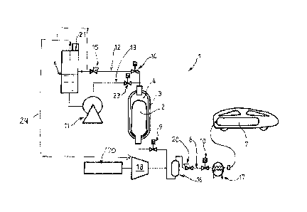
The example of a filling station 1 shown in figure 1 conventionally includes a
source store 3 of fuel gas (such as hydrogen) and a gas transfer circuit 8.
The gas
transfer circuit 8 has an upstream first end connected to the source store 3
and a
downstream second end intended to be in fluid communication with the tank 7 to
be filled (for example via a quick-connect system at the end of a hose).
The gas transfer circuit 8 includes at least one valve 9, 10 for controlling
the
transfer of gas from the source store 3 to the tank 7. For example, the
circuit can
include between the source store 3 and the downstream end a first valve 9 (for
example a controlled valve), a pressure regulator 20 then a second valve.
According to one advantageous feature, the source store 3 includes a rigid,
for example composite, outer wall and a flexible sealing wall 2 that is
arranged
inside the space defined by the rigid outer wall.
The flexible wall 2 therefore forms a flexible bladder defining a sealed
storage space for the fuel gas.
The upstream first end of the circuit 8 is connected to the storage space
defined by the flexible wall 2. The space located between the flexible wall 2
and
the outer wall is connected to a circuit 12, 13 for transferring liquid in the
source
store 3 in order to fill or extract the liquid in the source store 3 and
thereby to
.. control the pressure in the store 3 when filling and/or extracting fuel gas
inside the
sealing wall 2.
Without this being limiting on the invention as such, the source storage
structure 3 can conform to that described in the document EP2438346A1. In
particular, the flexible sealing wall 2 can be connected to the rigid wall
only at the
level of a neck or orifice of the source store 3. Likewise, this flexible
sealing wall 2
can be mounted either permanently in the rigid wall or removable, notably for
inspection and to enable its replacement if necessary. For example, the rigid
wall
of the source store 3 is made from a composite material. In other words this
CA 02981599 2017-10-03
WO 2016/162626 6
PCT/FR2016/050772
2015P00073 CA
source store can be an IV type tank with an intermediate liner positioned
between
the flexible wall 2 (bladder) and the rigid wall of the store.
Of course, any other appropriate structure can be envisaged. Likewise, the
flexible wall can be replaced by any other equivalent mobile or deformable
partition system enabling separation of the gas from the liquid.
In this way, a vehicle tank 7 can be filled in an isobaric manner by injecting
an incompressible fluid into the space between the flexible wall 2 confining
the gas
and the rigid wall.
The liquid is for example water (where applicable with antifreeze added to
it), oil (mineral, silicone or other oil) or any other appropriate liquid or
fluid.
The necessary volume of the source store 3 is preferably of an order of
magnitude equal to the volume of the tank 7 to be filled. The source store 3
of the
station 1 advantageously has a volume slightly greater than the volume of the
tank
7 in order to prevent excessive crushing of the bladder (flexible wall 2)
during the
transfer of gas at the end of filling.
The transferred gas flow rate can be controlled entirely by controlling the
flow rate of liquid introduced into the source store 3. This can make it
possible to
dispense with a filling flow rate control valve.
As shown in figure 1, the liquid transfer circuit 12, 13 can include a liquid
container 6 and a pump 11 adapted to enable the transfer of liquid from the
liquid
tank 6 to the source store 3 when necessary (notably at a particular flow
rate).
As shown, the liquid transfer circuit 12, 13 can include a first pipe 13
including the pump 11 (and preferably a valve 23) for transferring liquid from
the
liquid container 6 to the store 3 and an outlet second pipe 12 to enable the
transfer
of the liquid and where applicable of the gas from the store 3 to the liquid
container
6. The outlet pipe 12 can include a system of valve(s) 14, 15, for example a
first
valve 14 in series with a pressure regulator or a pressure relief valve.
This forms a venting system for maintaining a particular pressure difference
between the liquid container 6 and the source store 3. In particular, the
container 6
can be at the ambient atmospheric pressure.
Accordingly, in the case of the hydrogen fuel gas, the permeation hydrogen
having migrated through the bladder 2 and dissolved in the liquid can be
collected
in the source store 3 and degassed in a controlled and centralized manner via
a
CA 02981599 2017-10-03
WO 2016/162626 7
PCT/FR2016/050772
2015P00073 CA
vent 21. This gas can if required be recovered, possibly dried and de-oiled,
and
recompressed and reused, for example reinjected into the source store 3.
As diagrammatically indicated by the dashed line or lines 24, the recovered
gas can be recycled (used) at the inlet of the compressor 18. This increases
efficiency and reduces losses.
The station 1 can include a compressor 18 and/or respectively a pump
associated with an evaporator for filling the source store 3.
This compressor 18 (or the pump with evaporator fed with liquefied gas)
can be connected to the gas transfer circuit 8 (for example via a valve 22,
see
figure 2) and in particular to the source store 3 to enable filling of the
source store
3 with pressurized gas.
To fill the space defined by the flexible wall 2 with fuel gas hydrogen
supplied by the source 170 can be compressed/evaporated to a particular
pressure, for example a pressure greater than 900 bar.
This pressure can be controlled by the pressure regulator 15 on the outlet
pipe 12 and/or via the other valve 14 on this pipe 12.
When filling the store 3, the incompressible liquid contained therein is then
evacuated to the liquid container 6.
The pressure regulator 15 on the outlet pipe can be set to a pressure
greater than the pressure of the downstream pressure regulator 20 on the
transfer
circuit 8.
When the source store 3 is full or contains sufficient fuel gas, a tank 7 can
be filled.
During such filling, a valve 14 on the outlet pipe 12 is closed whereas the
valve 23 on the pipe 13 including the pump 11 is open. The pump 11 can then be
started.
The flexible wall 2 is then emptied of its gas, and this gas is transferred
into
the tank 7 via the transfer circuit 8 (downstream valves 9 and 10 open).
A pressure regulator 20 can be provided in the transfer circuit 8 to maintain
the pressure inside the flexible wall 2 constant at a value slightly greater
than the
pressure set by the regulator 15 (less than 900 bar for example).
As shown, the transfer circuit 8 (the pipe connected to the tank 7 to be
filled) can include a heat exchanger 17 for cooling the gas and thus at least
partly
CA 02981599 2017-10-03
WO 2016/162626 8
PCT/FR2016/050772
2015P00073 CA
compensating the rise in temperature linked to the adiabatic compression in
the
tank 7. This can contribute to enabling filling in less than 5 minutes.
Moreover, and as shown in figure 1, an (adsorbant or other) tank or
separator 16 can be provided in the transfer circuit 8 to eliminate any
pollutants in
.. the gas before it enters the tank 7.
Figure 2 shows a variant embodiment that differs from that from figure 1
only in that the station 1 includes a plurality of (three) source stores 3.
The source
stores 3 are connected in parallel on the one hand to the first end of the gas
transfer circuit 8 (via respective valves 9) and on the other hand to the
liquid
transfer circuit 12, 13 (via respective valves 14, 19).
The source stores 3 can be filled successively and can be used
successively for successive fillings (notably in cascade). This plurality of
source
stores 3 can notably be provided or used when the tank 7 to be filled has a
volume
greater than a source store 3.
Moreover, to optimize the filling energy, the source stores 3 can be filled
with gas at different pressures (for example 200, 500 and 900 bar). In this
case,
the pressure regulators 15 and 20 are preferably of the controlled pressure
(adjustable pressure value) type. Accordingly, when filling and extracting
from a
first source store 3, the control pressure (regulators 20 and 15) can be set
at a low
first value (for example of the order of 200 bar), then an intermediate second
pressure (for example 500 bar) for a second source store 3 and finally a high
third
pressure (for example 900 bar) for the third source store 3.
For practical reasons the pump 11 can be used or dedicated to extraction
from a particular source store 3. For example, in this case, a pump 11 can be
designed for a first particular working pressure (for example 200 bar for
extraction
from a first source store), another pump can be provided for a second working
pressure of the second source store 3 (for example 500 bar) with a third pump
for
a third pressure for the third source store 3 (for example 900 bar).
As shown, the source store or stores 3 are preferably oriented and placed
vertically (gas interface at the bottom and liquid interface at the top). This
arrangement enables collection in the hydraulic circuit 12, 13 of hydrogen
that
diffuses through the flexible wall 2 in order to degas it in the container 6.
The table below gives comparative examples between the prior art solution
in the left-hand columns (a plurality of conventional buffer stores used in
cascade)
CA 02981599 2017-10-03
WO 2016/162626 9
PCT/FR2016/050772
2015P00073 CA
and the solution according to the invention in the right-hand columns (one
buffer
store according to the invention).
The four lines show four respective examples of hydrogen consumption that
the station must be able to achieve (in kg/day and the number of successive
fillings) to fill tanks filled at 700 bar.
The second column shows the number, the volume (in liters (I)) and the
pressure (in bar) of the source stores 3 used with the above constraints. The
third
column indicates the quantity of gas stored in this case in the buffer stores
3 (in
Nm3).
The fourth and fifth columns correspond to the second and third columns for
the solution according to the invention.
Finally the final column shows the (percentage) differences in the quantity
of gas stored in the source stores 3 according to the invention compared to
the
standard solution.
It is readily seen that the invention therefore makes it possible to reduce by
approximately 50% the quantities of gas stored in the station compared to the
standard solution. This confers advantages in terms of cost and safety.
For example, for a station carrying out three successive fillings (100 kg of
hydrogen filled per day), instead of mobilizing two source stores of 800
liters and
1060 Nm3 of hydrogen, the invention can meet this demand with a single smaller
buffer store (500 I) with a smaller quantity of stored gas (450 m3).
Moreover, the invention makes it possible to reduce the size of the
necessary second compression stage because this second stage is often also
used to top up tanks to be filled when effected by conventional pressure
balancing.
This can generate a substantial saving per station (for example more than
compensating the additional cost for the pump 11).
Of course, the invention can be applied to filling gases other than hydrogen,
for example natural gas, methane or other gases (and at different pressures).
The following table comparing sizes and numbers of source stores in
the case of filling hydrogen tanks:
Filling according to
Standard filling Stored
gas
the invention
Station quantity
gas gas
Stored Stored
Capacity Capacity
difference
CA 02981599 2017-10-03
WO 2016/162626 10
PCT/FR2016/050772
2015P00073 CA
(N m3) (Nm3)
100 kg/day by 1 x 800 I at 1060 1 x 500 I at 450
three 450 bar + 900 bar
-58%
consecutive 1 x 800 I at
fillings 875 bar
400 kg/day by 4 x 800 I at 2140 1 x 1360 I at 1224
eight 450 bar + 900 bar
-43%
consecutive 800 I at
fillings 875 bar
100 kg/day by 1 x 1300 I at 1722 1 x 10²⁰ I at 918
twice three 450 bar + 900 bar
-47%
consecutive 1 x 1300 I at
fillings 875 bar
400 kg/day by 8 x 800 I at 4280 1 x 2720 I at 2448
twice eight 450 bar + 900 bar
-43%
consecutive 2 x 800 I at
fillings 875 bar
Accordingly, whilst being simple and of relatively low cost, the invention
offers numerous advantages. It makes it possible to use fewer source stores 3
at
the station 1 having water volumes less than those of a standard station.
Moreover, the source stores 3 of the station can be filled and extracted in
an isobaric manner. This reduces the cycles of mechanical fatigue thereof.
The diffusion gas flow can moreover be collected at a particular location.
The flow rate of filling the tanks 1 can be controlled by the speed of the
pump 11.
Moreover, the gas extracted from the source stores 3 remains at constant
or quasi constant temperature. This simplifies the determination of the
dimensions
of a downstream cooling heat exchanger 17.