Note : Les descriptions sont présentées dans la langue officielle dans laquelle elles ont été soumises.
CA 02981602 2017-10-03
WO 2016/161505
PCT/CA2016/050311
TITLE: POLISHED ROD ROTATOR WITH HEIGHT ADJUSTER
TECHNICAL FIELD:
The present disclosure is related to the field of oil wells and wellhead
equipment, and more particularly to oil wells where extraction is carried out
by
using pumping equipment with reciprocating sucker-rods.
BACKGROUND:
During oil well operation, a bottom-hole pump is typically actuated by a
string of sucker rods; the uppermost rod is known as the polished rod or
polish
rod. To accomplish the pumping action from the well, reciprocating motion is
provided to the sucker rod string by suspending the polish rod from
a rocking beam by means of a suitable hanger.
The vast majority of oil wells have deviations from the vertical axis.
Therefore, reciprocating motion of the sucker rod string in wells results in
uneven wearing of both the sucker rods and well tubing. Intermittent rotating
action (usually clockwise direction looking down the well) can be provided by
a rod rotator to rotate the sucker rod string, resulting in a more even
wearing
1
Date Recue/Date Received 2022-06-16
CA 02981602 2017-10-03
WO 2016/161505
PCT/CA2016/050311
of the sucker rods and well tubing. Further, this rotation can prevent
unwanted
unscrewing of rods and, when used in conjunction with rod scrapers, can
reduce the build-up of wax and paraffin on the surfaces of tubing and sucker
rods.
A polished rod is typically supported by a thrust bearing within the
rotator by the means of a polished rod clamp. The clamp is used to create a
friction connection with the polished rod and prevent it from moving
downwards through the cylindrical opening in the rod rotator.
Vertical positioning adjustment between the string and the hanger is
necessary from time to time. However, this is only possible by repositioning
the polished rod clamp on the polished rod.
Unlike the reciprocating and rotary movements, which have been
subject to numerous technological advancements over time, the vertical
positioning adjustment has received little attention. The operation of a
vertical
positioning adjustment is a technically challenging operation requiring a high
degree of skill. It also carries a significant amount of risk due to the
possibility
of failure of the friction connection between the polished rod clamp and
polished rod, which can result in the polished rod, and the sucker rod string,
falling downhole and leading to damage of the downhole equipment.
Accordingly, there is need to provide a method and apparatus that can
overcome the short-comings of the prior art with respect to vertical height
adjustment. More particularly, an apparatus is needed that can provide an
improved method of vertically restraining the polished rod while offering
convenient and safe vertical positioning adjustment of the sucker rod string.
2
Date Recue/Date Received 2021-03-02
CA 02981602 2017-10-03
WO 2016/161505
PCT/CA2016/050311
SUMMARY:
Apparatus and methods are provided for rotating sucker rod strings of
pumping equipment and adjusting the vertical position of the sucker rod
string.
In some embodiments, the apparatus can include a tubular rod carrier or
spindle, which can be threaded on its external surface. A polished rod can run
through the rod carrier. In some embodiments, the rod carrier can be held in
place along the polished rod with a locking mechanism, for example, by taper
lock bushings or standard polished rod clamps, on the upper and lower ends
of the rod carrier.
Broadly stated, in some embodiments, an apparatus is provided for
adjusting the vertical position of a polished rod of a pump, the apparatus
comprising: a tubular rod carrier for receiving the polished rod therethrough,
the rod carrier having external threads; means for fixing the rod carrier to
the
polished rod; and a rotator surrounding the rod carrier, the rotator
comprising
a wheel and a main thrust bearing, the wheel being in threaded connection
with the external threads of the rod carrier and supported by the main thrust
bearing; wherein the rotation of the wheel relative to the tubular rod carrier
results in vertical movement of the polished rod and wherein the vertical
movement of the polished rod is accomplished without disengaging the
means for fixing the rod carrier to the polished rod.
Broadly stated, in some embodiments, a rotation unit can be positioned
along the threaded rod carrier. In some embodiments, the rotation unit can
comprise a worm wheel threaded to the rod carrier. A worm can be configured
3
Date Recue/Date Received 2021-03-02
CA 02981602 2017-10-03
WO 2016/161505
PCT/CA2016/050311
to intertwine with the worm wheel and a lever can be positioned proximate
one end of the worm so that adjustment/swinging of the lever can result in
rotation of the polished rod.
In some embodiments, the wheel is a worm wheel engaged by a worm.
In some embodiments, the means for fixing the rod carrier to the polished rod
comprises a locking mechanism. In some embodiments, the locking
mechanism comprises a taper lock. In some embodiments, the locking
mechanism comprises a polished rod clamp. In some embodiments, the
apparatus further comprises an adjustment locking mechanism comprising a
cross member to engage a support cable of pumping equipment. In some
embodiments, the worm is functionally attached to a lever to allow an operator
to rotate the worm using the lever. In some embodiments, the rotator further
comprises a ratchet mechanism positioned between the lever and the worm.
In some embodiments, the rotator comprises an additional ratchet mechanism
positioned proximate an end of the worm opposite of the lever. In some
embodiments, the worm comprises a splined worm shaft. In some
embodiments, the rotator comprises a casing to shelter the wheel. In some
embodiments, the casing comprises a removable top cover
Broadly stated, in some embodiments, a method is provided for
adjusting the vertical position of a polished rod of a pump, the method
comprising: releasing a locking mechanism between a rotator wheel and a rod
carrier; holding the polished rod in place to prevent rotation of the polished
rod
around its vertical axis; and adjusting the vertical positioning of the
polished
rod by rotating the rotator wheel in a desired direction; wherein the polished
4
Date Recue/Date Received 2021-03-02
CA 02981602 2017-10-03
WO 2016/161505
PCT/CA2016/050311
rod and the rod carrier are not separated during the adjustment of the
vertical
positioning of polished rod.
Broadly stated, in some embodiments, a method is provided for
adjusting the vertical position of the sucker rod string comprising: releasing
a
locking mechanism; using a back-up wrench or similar device to prevent
rotation of polished rod; rotating the worm in the desired direction to adjust
the
vertical position of the polished rod. In some embodiments, the lever can also
be used to adjust the height by flipping the lever along its longitudinal
axis.
In some embodiments, adjusting the vertical positioning of polished rod
is accomplished be rotating a worm within the rotator to rotate the rotator
wheel threadably engaged with the rod carrier. In some embodiments, the
rotating of the worm is performed by an operator adjusting a lever, the lever
being functionally attached to rotate the worm. In some embodiments, the
adjusting of the lever comprises flipping the lever along its longitudinal
axis to
determine a direction of rotation. In some embodiments, the method further
comprises the removal of a clutch from the rotator prior to rotating the worm.
In some embodiments, a cross member is used to prevent rotation of the
polished rod. In some embodiments, the cross member is extended to
engage adjacent support cables to prevent rotation of the polished rod. In
some embodiments, the method further comprises re-engaging the locking
mechanism between the rotator and the rod carrier; once a new, desired,
vertical position of polished rod has been achieved.
Broadly stated, in some embodiments, a rotator is provided for
surrounding a rod carrier of an apparatus for adjusting the vertical position
of
5
Date Recue/Date Received 2021-03-02
CA 02981602 2017-10-03
WO 2016/161505
PCT/CA2016/050311
a polished rod of a pump, the rotator comprising: a wheel and a main thrust
bearing, the wheel being in threaded connection with external threads of the
rod carrier and supported by the main thrust bearing; wherein the rod carrier
receives the polished rod therethrough, and the apparatus comprises means
for fixing the rod carrier to the polished rod; and wherein the rotation of
the
wheel relative to the rod carrier results in vertical movement of the polished
rod and wherein the vertical movement of the polished rod is accomplished
without disengaging the means for fixing the rod carrier to the polished rod.
In this way, the present disclosure describes apparatuses and methods
for adjusting the vertical position of the sucker rod string without having to
break the connection between the polished rod and the rod carrier while
providing rotation to the polished rod.
BRIEF DESCRIPTION OF THE DRAWINGS:
Figure 1 is a side elevation, cross-section, view depicting an
embodiment of an apparatus for rotating a string of sucker rods during the
operation of pumping equipment and vertical height adjustment of the sucker
rod string, the section plane being parallel to the worm axis.
Figure 2 is a partial, side elevation, cross-section, view of the
embodiment shown in Figure 1 with a lever, the section plane being
perpendicular to the worm axis.
Figure 3 is a partial, top, cross-section, view, of the embodiment of a
rotator shown in Figure 1, the section plane being through the worm axis and
perpendicular to the polished rod axis.
6
Date Recue/Date Received 2021-03-02
CA 02981602 2017-10-03
WO 2016/161505
PCT/CA2016/050311
Figure 4 Is a top, cross-section, view, of the embodiment shown in
Figure 1.
Figure 5 is an exploded, perspective, view of the embodiment of a
rotator shown in Figure 1 in the absence of the rod and rod carrier.
Figure 6 is a partially exploded, perspective, view of the embodiment
shown in Figure 1, showing the rod and rod carrier.
Figure 7 is a side elevation, cross-section, view depicting an
embodiment of an apparatus for rotating a string of sucker rods during the
operation of pumping equipment and vertical height adjustment of the sucker
rod string, the section plane being parallel to the worm axis.
Figure 8 is a partial, side elevation, cross-section, view of the
embodiment shown in Figure 7 with a lever, the section plane being
perpendicular to the worm axis.
Figure 9 is a partial, top, cross-section, view, of the embodiment of a
rotator shown in Figure 7, the section plane being through the worm axis and
perpendicular to the polished rod axis.
Figure 10 is a top, cross-section, view, of the embodiment shown in
Figure 7.
Figure 11 is a top, plan, view, of the embodiment shown in Figure 7.
Figure 12 is an exploded, perspective, view of the embodiment of a
rotator shown in Figure 7 in the absence of the rod and rod carrier.
Figure 13 is a partially exploded, perspective, view of the embodiment
shown in Figure 7, showing the rod and rod carrier.
7
Date Recue/Date Received 2021-03-02
CA 02981602 2017-10-03
WO 2016/161505
PCT/CA2016/050311
DETAILED DESCRIPTION OF THE EMBODIMENTS:
Apparatuses and methods are provided to rotate a string of
reciprocating sucker rods of wellhead pumping equipment, where the
apparatuses and methods can also provide convenient and safe vertical
positioning adjustment of the sucker rod string.
Terms such as 'vertical', as used herein, are understood to mean
approximate relative positions, and not words of precision.
In some embodiments, a tubular rod carrier, or spindle, can be fixed in
a position on the polished rod. The rod carrier can have threads along its
external surface. A rotation unit can be threaded on the rod carrier to
provide
intermittent rotation as desired. The position of the rotation unit on the rod
carrier can be manipulated conveniently and safely. By utilizing the
arrangements as described herein, it can become unnecessary to break the
connection between the polished rod and the rod carrier to adjust the vertical
position of the sucker rod string, as was required in prior art inventions.
Referring now to Figure 1, apparatus 10 for rotating a polished rod 14
and adjusting the vertical position of polished rod 14 is shown. In some
embodiments, apparatus 10 can comprise a tubular rod carrier 12, which can
be threaded on its external surface. A polished rod 14 can pass through the
rod carrier 12. In some embodiments, the position of the rod carrier 12 on the
polish rod 14 can be maintained through the use of locking mechanisms, for
example upper and lower taper-lock bushings 16, 18. During a vertical
adjustment, a cross member 20, such as a back-up wrench or spare piping
55, can be positioned over the upper taper-lock bushing and contact support
8
Date Recue/Date Received 2021-03-02
CA 02981602 2017-10-03
WO 2016/161505
PCT/CA2016/050311
cables 21, in order to prevent free rotation of the rod carrier 12 and polish
rod
14. However, those with ordinary skill in the art will understand that a
plurality
of other means may be used to ensure that the rod carrier 12 remains
immovable with respect to the polished rod 14, a traditional polished rod
clamp 15 and safety clamp 17 being included. Cross member 20 can be
removable and/or absent during normal operation, when a vertical adjustment
is not being made, therefore allowing free rotation of the rod carrier 12 and
polish rod 14.
In some embodiments, rotator 35, surrounding rod carrier 12, can be
supported by main crossbar 23, which can span between support cables 21,
and can be supported by cable ends 33. Main crossbar 23 can be varied as
desired. In some embodiments, main crossbar 23 can be configured to be
reduced in volume, reduced in mass, and/or reduced in manufacturing cost.
Within rotator 35, wheel 36 can be supported by a main thrust bearing
25. In some embodiments, wheel 36 can be a worm wheel. Wheel 36 can
also include a threaded core 56 for engaging and meshing with the external
threads of rod carrier 12. In some embodiments, main thrust bearing 25 can
comprise cone 27 and cup 29 components, as well as a cage and roller
assembly 31. Main thrust bearing 25 can use spherical or tapered bearings,
although it would be understood that functional equivalents could also be
used.
Referring now to Figure 2, a lever 24 can be provided in the depicted
embodiment that can provide for manual rotation of the rod carrier 12 and
polished rod 14. In such an arrangement, the swinging moment of lever 24
9
Date Recue/Date Received 2021-03-02
CA 02981602 2017-10-03
WO 2016/161505
PCT/CA2016/050311
can rotate worm 22. In some embodiments, the handle of lever 24 can
include a hole to which a rope can be tied. In some embodiments, handle of
lever 24 can also be labelled in a manner to reflect orientation of lever 24.
Accordingly, when attaching lever 24, it is oriented in the proper direction.
In
other embodiments, the handle of lever 24 may be operably substituted for
one or more motors for powered rotation of worm 22. In some embodiments,
one or more motor may be contained within casing 28, or may be external
thereto, provided that the one or more motor may be readily turned on/off by
operator. In some embodiments, at least one power switch to turn the one or
more motor on/off may be provided. It should be appreciated that the one or
more motor may be operative to rotate the worm in either direction (i.e. in a
clockwise or counterclockwise direction looking from the right, as will be
described in more detail below).
In some embodiments, a top cover 26 can be provided over casing 28.
A threaded spindle-locking nut 30 can be positioned between the worm wheel
36 and top cover 26. In some embodiments, spindle-locking nut 30 can be a
separate component from worm wheel 36. In some embodiments, spindle-
locking nut 30 can be integral with worm wheel 36
In some embodiments, a stud 32 can be positioned from worm wheel
36, through threaded spindle-locking nut 30 and through top cover 26. A nut
34 can be engaged with the upper portion of stud 32 through a threaded
connection. In some embodiments, the locking action can be achieved by
tightening the nut 34, which can further increases the friction in the
threaded
connection between the rod carrier 12 and threaded spindle-locking nut 30
thereby preventing unwanted movement between worm wheel 36 and rod
Date Recue/Date Received 2021-03-02
CA 02981602 2017-10-03
WO 2016/161505
PCT/CA2016/050311
carrier 12. Also, angular contact bearing 19 and main thrust bearing 25 can
ensure the integrity of apparatus 10 is maintained during normal operation,
during height adjustment, as well as during jarring, which is often induced in
order to free stuck valves of downhole pumps. Those with ordinary skill in the
art will understand that a plurality of other known locking solutions used in
the
industry and can be applied here.
Referring now to Figure 3, in some embodiments, a worm wheel 36 is
provided, which is shaped to be in meshing engagement with worm 22, said
worm 22 being connected to the lever 24 by the means of a one-way clutch
40. In such an arrangement, the swinging movement of the lever 24 can
produce one-way indexing rotation of the worm 22 and corresponding one-
way indexing rotation of the worm wheel 36.
At the opposite end of the worm 22, some embodiments can include a
polished rod one-way clutch 42 to prevent unwanted movement of the
polished rod 14 in the counter-clockwise direction when looking down the well.
Some embodiments can operate without polished rod one-way clutch 42,
where the opposite end of the worm 22 can end in an engagement means 43,
such as a male hex to be engaged by the operator using a tool (for example,
a pneumatic tool, such as an air ratchet). Such means for engagement can
also be in other forms, such as a female square, or other functional
equivalents.
Those with ordinary skill in the art will understand that a plurality of
different ratcheting mechanisms and/or one-way clutches can be used to
accomplish the rotation of the polished rod and are not limited to the
embodiments described herein.
11
Date Recue/Date Received 2021-03-02
CA 02981602 2017-10-03
WO 2016/161505
PCT/CA2016/050311
In some embodiments, the apparatus 10 can include bearings 44, 46.
These bearings can ensure geometrical positioning of the worm 22 with the
worm wheel 36.
Figure 4 shows apparatus 10 in contact with support cables 21.
Referring now to Figure 5, an exploded view of a rotator 35
embodiment of apparatus 10 is shown. Some embodiments can also include
splines on worm shaft 38 to keep it aligned in the rotational device and
transfer rotational movement from the lever 24 to worm 22. A pin 48 can be
included in some embodiments to keep the lever 24 in position at the end of
the worm shaft 38. In these embodiments, the pin 48 can be removed so that
the lever 24 can conveniently be taken off the end of the worm 22 and be
repositioned.
Referring now to Figure 6, the polished rod 14 and rod carrier 12 can
pass through the rotator 35 in some embodiments such that swinging motion
of the lever 24 can result in rotational movement of the polished rod 14. In
some embodiments, locking nuts 50, 52 can be engaged with the rod carrier
12 by threads. Clamping the locking nut 50,52 and taper locks 16, 18 by bolts
54 can prevent unwanted movement of the rod carrier 12 with respect to
polish rod 14.
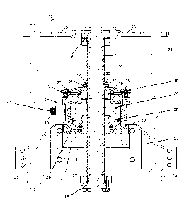
Referring now to Figure 7 to Figure 13, further embodiments of
apparatus 10 and rotator are shown.
In some embodiments, standard polish rod clamps can be used as
main clamp 15 and/or safety clamp 17. Safety clamp 17 can remain
stationary and not be moved to provide safety. In the absence of a properly
positioned safety clamp 17, and when rod 14 is adjusted upwards, spindle 12
12
Date Recue/Date Received 2021-03-02
CA 02981602 2017-10-03
WO 2016/161505
PCT/CA2016/050311
can continue to move upward and if it goes too far, spindle 12 can thread it
all
the way out of rotator 35. In order to prevent such dethreading, the distance
from the lower edge of the main crossbar 23 to top of safety clamp 17, can be
set so that safety clamp 17 can butt up against the bottom of the main
crossbar 23, prior to the dethreading of spindle 12, when rod 14 and spindle
12 are adjusted upwards. In some embodiments, a distance of five inches can
be used, although it would be appreciated that other distances can be used as
required.
Further, in some embodiments, cross member 20 can be truncated so
as it does not engage support cables 21 directly, but cross member 20 can
have arms configured to receive extension members 55, such as pieces of
pipe available to the operator, that when disposed on cross member 20,
extension members 55 can contact support cables 21. Such contact can then
allow for a height adjustment to be made will preventing or reducing rotation.
In some embodiments, a regular, non-angular, bearing assembly 191
can be used rather than angular contact bearing 19. The bearings and
bearing assemblies can be sealed and the cavity can be filled with grease
through grease nipples 53. Further, in some embodiments, rotator 35 can be
sealed internally and grease nipples 53 can be used to fill in the cavity so
the
upper cavity is fully filled with grease. A grease outlet can be used with a
plug,
such that the cavity can be filled with grease to the point that grease comes
out of the outlet, and at that point, the plug can be inserted into the
outlet. As
rotator 35 can be rotating, the grease can be distributed and spread
throughout the unit. When bearings 19, 191 and rotator 35 cavities above and
under the bearings 19, 191 are full of grease and sealed, traditional rotator
13
Date Recue/Date Received 2021-03-02
CA 02981602 2017-10-03
WO 2016/161505
PCT/CA2016/050311
contamination problems are ameliorated.
Further, a load cell can be disposed on apparatus 10, in some
embodiments, between the body of rotator 35 and crossbar 23. When using
prior art apparatuses and methods, an operator preforming a height
adjustment has to blindly guess the tap position of the sucker rod hitting
bottom. According to the present disclosure, however, the load cell can assist
in finding and/or predicting the tap position by converting an input of
mechanical force into an electrical output signal which can be read as feed-
back. The readings can change due to the weight of the rod and friction.
Accordingly, the load cell can be calibrated and readings can be made that
reflect the changes in the mechanical input. In operation, one would bring the
horsehead down, read the load cell, and in combination with processing or
analyzing the load cell and readings thereof, systems and/or methods can be
used to predict the tap position so as to prevent damage to downhole
equipment.
In some embodiments, the apparatus and methods are capable
transmitting rotational movement to the polished rod 14 while offering a
convenient and safe method of vertical height adjustment of the sucker rod
string.
Initial vertical positioning of the polished rod 14 can be achieved in a
manner similar to established practices in the industry. The rotator assembly
35 can be mounted to the polished rod 14 by the means of taper-lock
bushings 16, 18 or other traditional methods. In the normal course, the rod
carrier, polished rod 14, wheel 36, and main thrust bearing 25, can rotate
together, simultaneously, and a vertical height adjustment is not made.
14
Date Recue/Date Received 2021-03-02
CA 02981602 2017-10-03
WO 2016/161505
PCT/CA2016/050311
For the purposes of periodic re-adjustments, however, using the
apparatuses and methods as described herein, it is no longer necessary to
break the connection between the polished rod 14 and the rod carrier 12. In
operation, the apparatus 10 can be used to re-adjust the vertical height of
the
sucker rod string by first releasing the locking nuts 34. Next, in some
embodiments, a back-up wrench, spare pipe 55, cross member 20, or other
means can be used to prevent rotation of polished rod 14, while wheel 36 and
main thrust bearing 25 continue to be free to rotate. To adjust the vertical
positioning of polished rod 14, the worm 22 of some embodiments can be
rotated in the desired direction, which will depend on a combination of
threads
used, worm 22 handing, and relative position of the lever 24. If lever 24 is
used to adjust the vertical positioning, in some embodiments flipping the
lever
24 along its longitudinal axis can determine the direction of rotation.
In some embodiments, optional polished rod one-way clutch 42 can be
removed prior to height adjustment and replaced following the height
adjustment To move polished rod 14 up, the operator can work the lever 24.
In some embodiments, when worm 22 is rotated in a clockwise direction
looking from the right, movement of polished rod 14 will be upwards and can
be accomplished with lever 24. To move polished rod 14 down, the opposite
end of worm 22 can be worked the other way, for example by using
engagement means 43 and ratchet, and worm 22 is rotated in a clockwise
direction looking from the left, movement of polished rod 14 will be
downwards.
In some embodiments, lever 24 can be removed. Safety pin 48, and
Date Recue/Date Received 2021-03-02
CA 02981602 2017-10-03
WO 2016/161505
PCT/CA2016/050311
washer 49 can be removed and, handle of lever 24 can be slid off. In such
embodiments, once pin 48 is removed, then worm 22 is moveable and can be
moved in either direction using engagement means on the far end of worm
22. As such, using a socket and ratchet (for example, an air ratchet) on this
side, the operator can decide which way to adjust the height.
Without limitations, and for purpose of illustration only, if the worm 22
and rod carrier 12 can be both threaded as "right-hand" and if the worm 22 is
rotated clockwise looking at the lever-end as shown in the accompanying
figures, the worm-wheel 36 can rotate clockwise looking from above. If rod
carrier 12 is prevented from rotating around its axis, for example by the
means of cross-member 20, the rod carrier 12 can be forced to move upwards
relative to the worm-wheel 36 and the main thrust bearing 25. In a similar
manner, if the worm 22 is rotated counter-clock-wise, the rod carrier 12 can
be forced to move downwards relative to the worm-wheel 36 and the main
thrust bearing 25.
Once a new, desired, vertical position of polished rod 14 has been
achieved, locking nuts 34 can be retightened to increase the friction
connection between wheel 36 and rod carrier 12 and to prevent unwanted
relative movement between the rod carrier 12 and the worm wheel 36. The
back-up wrench 20, and/or pipe 55 (if used) can be removed, lever 24 and
optional one-way clutch 42 can be brought to original working positions and
operation of the pump can be resumed.
Although a few embodiments have been shown and described, it will
be appreciated by those skilled in the art that various changes and
modifications might be made without departing from the scope of the
16
Date Recue/Date Received 2021-03-02
CA 02981602 2017-10-03
WO 2016/161505
PCT/CA2016/050311
invention. The terms and expressions used in the preceding specification
have been used herein as terms of description and not of limitation, and there
is no intention in the use of such terms and expressions of excluding
equivalents of the features shown and described or portions thereof, it being
recognized that the invention is defined and limited only by the claims that
follow.
While the above description details certain embodiments of the
invention and describes certain embodiments, no matter how detailed the
above appears in text, the invention can be practiced in many ways. Details
of the apparatuses and methods may vary considerably in their
implementation details, while still being encompassed by the invention
disclosed herein. These and other changes can be made to the invention in
light of the above description.
Particular terminology used when describing certain features or
aspects of the invention should not be taken to imply that the terminology is
being redefined herein to be restricted to any specific characteristics,
features,
or aspects of the invention with which that terminology is associated. In
general, the terms used in the following claims should not be construed to
limit the invention to the specific embodiments disclosed in the
specification.
Accordingly, the actual scope of the invention encompasses not only the
disclosed embodiments, but also all equivalent ways of practicing or
implementing the invention.
The above description of the embodiments of the invention is not
intended to be exhaustive or to limit the invention to the precise form
disclosed above or to the particular field of usage mentioned in this
17
Date Recue/Date Received 2021-03-02
CA 02981602 2017-10-03
WO 2016/161505
PCT/CA2016/050311
disclosure. While specific embodiments of, and examples for, the invention
are described above for illustrative purposes, various equivalent
modifications
are possible within the scope of the invention, as those skilled in the
relevant
art will recognize. The elements and acts of the various embodiments
described above can be combined to provide further embodiments.
While certain aspects of the invention are presented below in certain
claim forms, the inventors contemplate the various aspects of the invention in
any number of claim forms. Accordingly, the inventors reserve the right to add
additional claims after filing the application to pursue such additional claim
forms for other aspects of the invention.
18
Date Recue/Date Received 2021-03-02