Note : Les descriptions sont présentées dans la langue officielle dans laquelle elles ont été soumises.
HOSPITAL SUPPORT POLES WITH ONBOARD POWER UNITS
RELATED APPLICATIONS
100011 This application claims priority to U.S. Provisional Application
Serial Number
62/148,398 filed April 16, 2015, U.S. Provisional Application Serial Number
62/207,106
filed August 19, 2015, and U.S. Provisional Application Serial Number
62/221,409
filed September 21, 2015.
FIELD OF THE INVENTION
[0002] The invention relates to hospital accessory poles such as IV poles.
BACKGROUND
[0003] For many years, patients needing intravenous (IV) fluid
transfusions have been
moved by a patient transportation apparatus such as a wheelchair, wheeled bed,
stretcher,
gurney or the like while receiving intravenous (IV) transfusions by the use of
mobile IV
poles. These IV poles, however, suffer from a number of drawbacks.
SUMMARY
[0004] Embodiments of the invention relate to poles for hospital
accessories that include
an onboard power unit. The poles are typically for a clinical or hospital
environment, and can
dock to various devices such as booms, beds, wheelchairs, walkers, wagons, and
the like.
[00051 The poles can have a plurality of legs which hold wheels, typically
casters.
[0006] The poles can have wheels that can be small wheels, larger wheels
combinations
of smaller and larger wheels, with or without casters.
[0007] In some embodiments, the legs are not retractable but the mast may
be
extendable/retractable.
1
Date Regue/Date Received 2022-07-22
CA 02982589 2017-10-12
WO 2016/167917 PCT/US2016/023075
[0008] In some embodiments, the legs can be moved between an extended
configuration
where the wheels contact a floor and a retracted configuration where the legs
are drawn
inward and the wheels are lifted to reside off the floor.
100091 A medical accessory support pole, comprising: an elongate pole body;
a plurality
of wheels attached to the pole body; and an onboard power unit held by the
pole body,
comprising: a housing having a downwardly extending cylindrical channel
surrounding a
segment of the pole body; a plurality of circumferentially spaced apart
electrical receptacles;
and a power cord in electrical communication with the electrical receptacles
extending
outward from the housing.
100101 The pole can include a power cord retraction mechanism held by the
housing in
communication with the power cord to allow automatic or semi-automatic
retraction of the
power cord into the housing.
100111 The power cord can have a length of between 5-12 feet, and, in a
fully or partially
retracted configuration, a length of the power cord can reside inside the
housing in stacked
circular layers about the cylindrical channel.
100121 The retraction mechanism can include a rotation coupler that can be
in
communication with a compai tuient holding a length of the power cord.
100131 The housing can have a neck that angles out to a receptacle surface,
then extends a
vertical distance to define a cord compartment.
[00141 The cord compartment can be rotatable inside the housing about a
pole axis of a
centerline of the cylindrical channel.
100151 The pole can be a transformable pole having a plurality outwardly
extending legs
holding a respective wheel. The transformable pole can have a first extended
configuration
with the legs extending outward away from the pole body with the wheels on a
floor and a
second configuration with the legs are retracted to reside closer to the pole
body and the
wheels are lifted off the floor. The onboard power unit can be configured to
longitudinally
slide up and down in concert with a base as the legs retract and extend,
respectively.
[00161 The pole can include at least one cord grip attached to the pole
body. The cord
grip can include a plurality of circumferentially spaced apart and
longitudinally extending
2
CA 02982589 2017-10-12
WO 2016/167917 PCT/US2016/023075
accessory cord channels for holding segments of longitudinally extending
accessory power
cords.
[0017] At least one of the electrical receptacles can have an externally
visual color that is
different from one or more other of the electrical receptacles.
[0018] The power unit housing can be rotatable about a vertical pole axis
of the pole
body.
[0019] One or more of the electrical receptacles can have a different
socket orientation
from another of the electrical receptacles.
[0020] One or more of the electrical receptacles can be rotated to provide
a desired socket
orientation.
[0021] The housing can have an angled outer surface that extends away from
the
cylindrical channel and merges into a vertical outer wall. The angled outer
surface can be
angled at between 30-60 degrees from horizontal.
[0022] The pole can include wings held by an upper portion of the pole
body and a base
held adjacent the wheels. The housing can reside a distance above the wheels
by between 3-6
feet to reside closer to the wings of the pole than the base.
[0023] The pole body can include a docking alignment key member
circumferentially
extending between 15-45 degrees and longitudinally extending between 1-5
inches of a
segment of the pole body. The segment of the pole body with the key member can
have a
diameter that is less than a diameter of at least an adjacent lower portion of
the pole body.
The housing can reside a distance above the wheels by between 3-6 feet to
reside above the
key member. The housing can have an outer wall that extends radially outward a
greater
distance from the pole body than the key member.
[0024] Other embodiments are directed to a medical accessory support pole
that includes:
an elongate pole body; a base attached to a lower portion of the pole body
comprising a
= plurality outwardly extending legs; and a plurality of wheels attached to
the legs. The legs
have a first extended configuration with the legs extending outward away from
the pole body
with the wheels on a floor and a second configuration where the legs are
retracted to reside
closer to the pole body and the wheels are lifted off the floor. The pole also
includes an
3
CA 02982589 2017-10-12
WO 2016/167917 PCT/US2016/023075
onboard power unit attached to the pole body. The onboard power unit includes:
a housing
having a downwardly extending cylindrical channel surrounding a segment of the
pole; a
plurality of circumferentially spaced apart electrical receptacles; a power
cord in electrical
communication with the electrical receptacles extending outward from the
housing; and a
power cord retraction mechanism held by the housing in communication with the
power cord
to allow automatic or semi-automatic retraction of the power cord into the
housing. The
power cord can have a length of between about 5 feet and about 12 feet, and,
in a fully or
partially retracted configuration, a length of the power cord resides inside
the housing in
stacked circular layers about the cylindrical channel. The onboard power unit
is configured
to longitudinally slide up and down in concert with the base as the legs
retract and extend,
respectively.
[0025] The housing can be rotatable about the pole body. The housing can
include a
power cord compartment that is configured to rotate inside the housing about
the pole.
[0026] Still other embodiments are directed to a medical accessory support
pole that
includes: an elongate pole body; a base attached to a lower portion of the
pole body
comprising a plurality outwardly extending legs; and a plurality of wheels
attached to the
legs. The legs have a first extended configuration with the legs extending
outward away from
the pole body with the wheels on a floor and a second configuration where the
legs are
retracted to reside closer to the pole body and the wheels are lifted off the
floor. The pole
also has an onboard power unit attached to the pole body that includes: a
housing having a
downwardly extending cylindrical channel surrounding a segment of the pole; a
plurality of
circumferentially spaced apart electrical receptacles; a power cord in
electrical
communication with the electrical receptacles extending outward from the
housing; and a
power cord retraction mechanism held by the housing in communication with the
power cord
to allow automatic or semi-automatic retraction of the power cord into the
housing. The
power cord has a length of between about 5 feet and about 12 feet, and, in a
fully or partially
retracted configuration, a length of the power cord resides inside the housing
in stacked
circular layers about the cylindrical channel. The pole includes wings held by
an upper
portion of the pole body. The housing resides a distance above the wheels by
between 3-6
feet to reside closer to the wings of the pole than the base.
[0027] The pole body can have a docking alignment key member
circumferentially
extending between 15-45 degrees and longitudinally extending between 1-5
inches about a
4
CA 02982589 2017-10-12
WO 2016/167917 PCT/US2016/023075
segment of the pole body. The segment of the pole body with the key member can
have a
diameter that is less than a diameter of at least an adjacent lower portion of
the pole body.
The power unit housing can reside above the key member. The housing can
include an outer
wall that extends radially outward a greater distance from the pole body than
the key
member.
[0028] The housing can be rotatable about the pole body. The housing can
include a
power cord compartment that is configured to rotate inside the housing about
the pole.
[0029] Other embodiments are directed to methods of providing power to
hospital
equipment. The methods include: (i) providing a hospital support pole with a
plurality of
rollers and/or casters and comprising an on-board power shroud with a
plurality of electrical
receptacles; (ii) rolling the hospital support pole across a floor; extending
a power cord held
in a cord compartment of the on-board power shroud to have an exposed length;
and (iii)
plugging in thc power cord to an electrical receptacle of a hospital
electrical circuit to power
the receptacles of the on-board power shroud.
[0030] Optionally, in response to a user unplugging the power cord,
automatically
retracting the exposed length of the power cord back into the cord
compartment.
[0031] Optionally, electromechanically or mechanically automatically
raising the hospital
support pole so that the rollers and/or casters are off floor before, during
or after plugging in
the power cord.
[0032] It is noted that any one or more aspects or features described with
respect to one
embodiment may be incorporated in a different embodiment although not
specifically
described relative thereto. That is, all embodiments and/or features of any
embodiment can
be combined in any way and/or combination. Applicant reserves the right to
change any
originally filed claim or file any new claim accordingly, including the right
to be able to
amend any originally filed claim to depend from and/or incorporate any feature
of any other
claim although not originally claimed in that manner.
00331 These and other aspects of the invention are described in more detail
in the
accompanying description and drawings.
CA 02982589 2017-10-12
WO 2016/167917 PCT/US2016/023075
BRIEF DESCRIPTION OF THE DRAWINGS
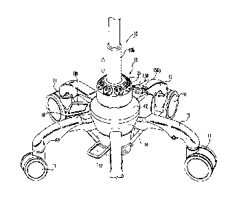
[0034] FIG. 1 is a perspective view of a portion of a transformable pole
according to
embodiments of the present invention.
[0035] FIGS. 2A and 2B are enlarged views of retracted/stowed configuration
and an
extended operational configuration, respectively, of a transformable pole
according to
embodiments of the present invention.
[0036] FIG. 3 is a side perspective view of an IV pole that can comprise a
power strip
unit and/or an oxygen tank holder according to embodiments of the present
invention
according to embodiments of the present invention.
[0037] FIG.4A is a greatly enlarged front perspective view of an exemplary
power unit
according to embodiments of the present invention.
[0038] FIG. 4B is a partially transparent view of the device shown in FIG.
4A.
[0039] FIG. 4C is a sectional view of the device shown in FIG. 4A according
to some
embodiments of the present invention.
[0040] FIG. 4D is a partially transparent view of the sectional view shown
in FIG. 4C.
[0041] FIG. 5 is a side perspective view of another embodiment of a pole
with an
onboard power unit according to embodiments of the present invention.
[0042] FIG. 6 is a side perspective view of an embodiment of the pole with
the onboard
power unit according to embodiments of the present invention.
[0043] FIG. 7 is a schematic illustration of an onboard power unit with
stacked electrical
receptacles according to embodiments of the present invention.
[0044] FIG. 8 is a side perspective view of another embodiment of a pole
with an
onboard power unit according to embodiments of the present invention.
[0045] FIG. 9 is an enlarged view of the device shown in FIG. 8.
[0046] FIG. 10A, 10B and 11 are schematic illustrations of a power circuit
for an
onboard power unit of an accessory pole according to embodiments of the
present invention.
6
CA 02982589 2017-10-12
WO 2016/167917 PCMS2016/023075
DETAILED DESCRIPTION
[0047] The present invention now will be described more fully hereinafter
with reference
to the accompanying drawings, in which illustrative embodiments of the
invention are shown.
Like numbers refer to like elements and different embodiments of like elements
can be
designated using a different number of superscript indicator apostrophes
(e.g., 90, 90', 90",
90'").
[0048] In the drawings, the relative sizes of regions or features may be
exaggerated for
clarity. This invention may, however, be embodied in many different forms and
should not
be construed as limited to the embodiments set forth herein; rather, these
embodiments are
provided so that this disclosure will be thorough and complete, and will fully
convey the
scope of the invention to those skilled in the art. The term "Fig." (whether
in all capital
letters or not) is used interchangeably with the word "Figure" as an
abbreviation thereof in the
specification and drawings. In the figures, certain layers, components or
features may be
exaggerated for clarity, and broken lines illustrate optional features or
operations unless
specified otherwise. In addition, the sequence of operations (or steps) is not
limited to the
order presented in the claims unless specifically indicated otherwise.
[0049] It will be understood that, although the terms first, second, etc.
may be used herein
to describe various elements, components, regions, layers and/or sections,
these elements,
components, regions, layers and/or sections should not be limited by these
terms. These
terms are only used to distinguish one element, component, region, layer or
section from
another region, layer or section. Thus, a first element, component, region,
layer or section
discussed below could be termed a second element, component, region, layer or
section
without departing from the teachings of the present invention.
[0050] Spatially relative terms, such as "beneath", "below", "bottom",
"lower", "above",
"upper" and the like, may be used herein for ease of description to describe
one element or
feature's relationship to another element(s) or feature(s) as illustrated in
the figures. It will be
understood that the spatially relative terms are intended to encompass
different orientations of
the device in use or operation in addition to the orientation depicted in the
figures. For
example, if the device in the figures is turned over, elements described as
"below" or
"beneath" other elements or features would then be oriented "above" the other
elements or
features. Thus, the exemplary term "below" can encompass orientations of
above, below and
7
CA 02982589 2017-10-12
WO 2016/167917 PCT/US2016/023075
behind. The device may be otherwise oriented (rotated 900 or at other
orientations) and the
spatially relative descriptors used herein interpreted accordingly.
[0051] The term "about' refers to numbers in a range of +/-20% of the noted
value.
[0052] As used herein, the singular forms "a", "an" and "the" are intended
to include the
plural forms as well, unless expressly stated otherwise. It will be further
understood that the
terms "includes," "comprises," "including" and/or "comprising," when used in
this
specification, specify the presence of stated features, integers, steps,
operations, elements,
and/or components, but do not preclude the presence or addition of one or more
other
features, integers, steps, operations, elements, components, and/or groups
thereof It will be
understood that when an element is referred to as being "connected" or
"coupled" to another
element, it can be directly connected or coupled to the other element or
intervening elements
may be present. As used herein, the term "and/or" includes any and all
combinations of one
or more of the associated listed items.
[0053] The terms "accessory" and "accessory devices" are used
interchangeably to refer
to any clinical or hospital device that may be desirable to be provided for
and/or moved with
a patient using a support pole on wheels such as an IV pole, and can include
one or more of
IV systems, IV bags, IV bag supports, pumps, pump supports, monitors, monitor
supports,
tables, trays, oxygen tank/canisters and canister holders 250 (Figure 3) and
the like.
100541 Turning now to the figures, FIG. 1 illustrates a pole 10 with an
onboard power
unit 15 with a plurality of circumferentially spaced apart plug-in electrical
receptacles 25 and
a power cord 150. The pole 10 can be a transformable pole. The power cord 150
can have
an external male plug-in connector 150p.
[0055] The tenn "transformable" when referring to some embodiments of the
pole 10
means that the pole 10 can transform between at least two different
configurations, typically
including a stowed configuration with the wheels 11 off of/above a support
floor as shown in
FIG. 2A and an extended configuration with the wheels 11 on the floor as shown
in FIG. 2B
with the wheels 11 able to provide a weight bearing support for the upwardly
extending
tubular pole body 10b. The pole 10 can include a lift mechanism 14 held by the
base 12.
The lift mechanism 14 can slide up and down relative to a lower end portion of
the pole body
10b. The lift mechanism 14 holds legs 13 that are attached to the wheels 11.
The legs 13 can
pivot inward and outward relative to the base 12 to be able to retract and
extend the wheels
8
11 in the stowed and extended positions, respectively. The pole 10 can include
at least one
foot lever for moving between the stowed and extended positions.
100561 As shown in FIG. 1, the pole 10 can have a manually-actuated foot
lever 18
accessible under a lift tab 18t in communication with the lift mechanism 14
for engaging an
onboard (e.g., gas spring) actuator that raises the wheels 11. The pole 10 may
also have a
second lever 17 for lowering the wheels 11. The second lever 17 can manually
lower the
wheels 13 from force applied to the second lever 17. In some embodiments, the
wheels 11
are caster-type wheels capable of freely rotating along a leg-wheel
connection. Although in
this particular depiction there are five legs 13 with five four-inch caster-
type wheels 11,
embodiments with different numbers of legs (such as 1, 2, 3 or 6 or more) and
different sized
or types of wheels, or combinations of different types or sizes, larger or
smaller or
combinations of different size wheels may be used.
100571 The lift mechanism 14 may include a gas spring as described in U.S.
Patent No.
7,918,422. Alternatively, other lift mechanisms 14 including, for example,
electric
motor or pneumatic driven gears and/or links may be used.
100581 FIGS. 2A and 2B are enlarged views of retracted/stowed
configuration and an
extended operational configuration, respectively, of a transformable pole 10
that can include
the onboard power unit 15 according to embodiments of the present invention.
100591 As shown in FIG. 3, the tubular pole body 10b can include an upper
mast 16
residing between wings lOw under a suspension support 1 Os for suspending bags
of fluids for
patient administration, such as IV fluids and the like. The wings 10w can
support patient
monitors and/or other devices. See, e.g., U.S. Patent Nos. 7,497,407;
7,918,422; 7,735,789;
and US Patent Application Publication 2013/0181100.
100601 As shown in FIG. 3, the pole 10 can include the power unit 15 with
the
circumferentially spaced apart receptacles 25 and may include a secondary
onboard power
strip unit 15' and/or a gas canister holder 250 that can releasably hold a gas
canister 251.
[00611 Turning again to FIG. 1, in some embodiments, the onboard power
unit 15 can be
configured to longitudinally slide up and down as indicated by the vertically
oriented arrow.
9
Date Regue/Date Received 2022-07-22
CA 02982589 2017-10-12
WO 2016/167917 PCT/US2016/023075
The power unit 15 can be incorporated into the base 12 or reside above the
base 12 and
slidably cooperate with the base 12 to be able to slide up and down in concert
with the base
12 as the legs 13 retract and extend, respectively. The longitudinal travel
can be between 2-
inches, typically about 4-7 inches, such as about 4 inches, about 5 inches,
about 6 inches
about or about 7 inches and in particular embodiments can be about 6 inches.
[0062] The power cord 150 is preferably configured as a retractable power
cord as shown
in FIG. 1 and 4A-4D. However, the power cord 150 may also be configured as a
loose
external length of cable/cord that can optionally be held about a cord
support/mount on the
pole body 10b and/or on the body of the power unit 15.
[0063] Although the power unit 15 is shown with eight separate electrical
receptacles 25,
it may include less or more, e.g., a single receptacle or between 2-10
circumferentially spaced
apart receptacles 25, in some embodiments.
10064] In some embodiments, the power cord 150 can have a length that is a
length of a
hospital bed plus between 2-6 feet, typically between about 8-12 feet such as
about 8 feet,
about 8.5 feet, about 9 feet, about 9.5 feet, about 10 feet, about-10.5 feet,
about 11 feet, about
11.5 feet and about 12 feet. The cord 150 can have a suitable power and
amperage rating and
associated diameter for supplying the power input 15i (FIG. 10A, 10B, 11) to
the power
circuit 15c of the onboard power unit 15. The cord 150 can have a 110 volt, 15
to 20
amperage rating. The cord 150 can comprise a 10 gage wire size.
[0065] Referring to FIG. 4A-4D, in some embodiments, the power unit 15 can
orient the
receptacles 25 in different directions or the unit 15 can have at least one
that faces a different
direction than another, e.g., one that faces the front, one that faces the
back, one that faces a
side or wing 10w, and the like. The power unit 15 can have one or more
individually
rotatable (swivel) electrical receptacles 25 as shown by the arrows adjacent
two of the
respective receptacles 25 for altering orientation. One or all of the
receptacles 25 may have a
fixed receptacle orientation.
100661 Referring to FIG. 4A, the power unit 15 can have a housing 15h that
rotates about
the vertical axis A of the pole 10. The angular rotation of the housing 15h
can be between
30-360 degrees, including about 30 degrees, about 60 degrees, about 90
degrees, about 120
degrees and about 180 degrees. The plug-in receptacle 25r rotation and/or
rotation of the
CA 02982589 2017-10-12
WO 2016/167917 PCT/US2016/023075
housing 15h can allow easier access of cords for various accessory components
held by the
pole 10 that may need powering, such as monitors, pumps and the like.
[0067] As shown in
FIG. 4A-4D, the power unit housing 15h can have a longitudinally
extending open center channel 30 that is sized and configured to surround the
tubular pole
body 10b. The channel 30 can have a diameter between about 1.25 inches and
about 2 inches
and a length between about 2 inches and about 4.5 inches.
[0068] FIG. 4B-4D
show that the housing 15h can have a cord port 152 and an internal
open vertical space extending below (as shown) or above the receptacles 25
with a vertical
height "h" sufficient to accommodate a cord retraction mechanism 40 with a
plurality of
stacked layers/loops 151 of cord extending about and inside the channel 30 of
the housing
15h.
[0069] The
retraction mechanism 40 can be configured to be able to automatically or
semi-automatically extend and/or retract the power cord 150, e.g., act as a
rotatable "take-up"
reel. To be
clear, the term "retraction mechanism" refers to a mechanical or
electromechanical device that can be used to either extend or retract or both
extend and
retract a length of power cord from an enclosure/unit housing 15h. The
retraction mechanism
40 can have a rotation coupler 41 that can rotate the cord compartment 42 in
the housing
open space 32 that holds the stacked layers of cord 151. The compartment 42
can have upper
and lower members 43, 44 with a circular outer perimeter attached at an inner
edge portion
thereof by a downwardly extending inner wall 45 with a cylindrical opening
that that aligns
with the longitudinally extending channel 30 of the unit housing 15h.
[0070] The housing
15h outer wall 15w can define the outer enclosure of the
compartment members 43, 44. The compartment 42 can have a radial length
extending from
the inner wall 45 outward to the outer perimeter thereof that is between about
3-10 inches.
The retraction mechanism 40 can be configured to operate with sufficient drag
or torque so
that the cord 150 is not allowed to retract or extend at a speed that may
cause a tipping issue
of the pole 10. The retraction mechanism 40 can include a preloaded spring
providing
constant or substantially constant cord retention force (e.g., within about
10% of a defined
cord retention force). The retraction mechanism 40 can include a spring loaded
plunger 49
(Fig. 4B) that holds the spring and can provide a radially inwardly extending
cord retention
force onto the cord compartment through the power unit housing 15h, e.g., from
either the
11
CA 02982589 2017-10-12
W02016/167917 PCT/US2016/023075
upper compartment member 43 and/or lower compartment member 44 (Fig. 4C),
typically
via only the lower compartment member 44.
[0071] In some embodiments, the unit housing 15h can include a cord lock
155 (FIG.
4A) to electronically lock and/or allow a user to manually lock and/or unlock
the cord 150 at
a desired external length and/or to retain the cord 150 inside the housing 15h
until pole 10 is
in a stable environment or position. Although FIG. 4A illustrates a lock 155
adjacent the
cord port 152, it may alternatively or additionally be inside the housing
adjacent the
retraction mechanism to inhibit rotation of the rotation coupler 41.
[0072] The pole 10 can have a user input 101 (Figure 11) that allows a user
to
affirmatively indicate when an action to deploy the power cord or the retract
the power cord
is desired. The user input can be a manual and/or electrical input. The user
input 10i can be
in communication with the lock 155 and/or retraction mechanism 40 to allow a
user to
selectively extend and/or retract the power cord 150. In some embodiments, the
lock 155 can
lock the power cord 150 to prevent extension from the housing 15h until the
housing 15h
itself is locked into a desired circumferential orientation (such as where the
unit housing 15h
is able to rotate about the pole axis A).
[0073] FIG. 5 illustrates that the onboard power unit 15 of the pole 10 can
have at least
two receptacles 25 that have a different color 25c from each other (indicated
by the different
surface shadings/finishes on respective receptacles). In some embodiments,
each receptacle
25 can have a different visual appearance such as one or more of a different
color 25c,
opacity, intensity or hue to allow a user to visually identify what receptacle
25 is used for a
particular accessory power cord 200 to an accessory held by the pole 10. In
some
embodiments, as shown in FIG. 5, the pole 10 can also include at least one
accessory cord
grip 300 with circumferentially spaced apart longitudinally extending cord
grip channels 310.
The cord grip 300 can be integrated into the outer wall of the pole and/or can
be provided as a
removable sleeve 300s (as shown). For the integrated version, the pole 10 can
comprise one
or more overmolded segment with polymeric and/or elastomeric cord grips. The
cord
channels 310 can have an open externally facing perimeter segment 310e. The
channels 310
can elastically deform to receive and snugly hold a respective accessory cord
200.
[0074] In some embodiments, the pole 10 can hold a plurality of the cord
grips 300, one
above another for limiting dangling cords for overhead accessories.
12
CA 02982589 2017-10-12
WO 2016/167917 PCT/US2016/023075
10075] In some embodiments, the cord grips 300 can be configured with two
or more
channels 310 having a different color channel 310, such as 310ci, 310c2,
310c3. Optionally,
the different color channels 310c can be color-coded to match a respective
color 25c of a
receptacle 25.
[0076] FIG. 6 illustrates that the power unit housing 15h can be configured
to lockingly
engage the pole 10 to lock into a desired circumferential orientation, when
the unit housing
15h is rotatable about the pole axis A, such as using one or more cooperating
lock and release
members such as a radially extending finger 19 and radially extending slot 23.
As shown in
FIG. 6, the pole 10 can have at least one finger 19 and the unit housing can
have a
cooperating at least one slot 23. As also shown in FIG. 6, the unit housing
(bottom) can have
at least one finger 19 and the pole base 12 can have a cooperating at least
one slot 23
configuration. While the radially extending slot 23 is shown on the base 12
and upper unit
housing segment 15h and the radially extending finger 19 is shown on the lower
unit housing
15h and the pole 10, these configurations can be reversed (and both are not
required). Other
radial-position lock configurations may be used.
[0077] FIG. 7 illustrates that the power unit 15 can have vertically
stacked receptacles
25, at least one above at least one other. Both the upper and lower 15u, 15/
receptacle
compartments can rotate or both can be stationary or one can rotate and one
can be stationary.
Each of the receptacles in the upper and lower receptacle compartments 15u,
15/ can be in
electrical communication with a single power cord 150 or each can be in
communication with
a separate respective power cord 150.
[0078] The receptacles 25 can have front faces that angle outward from the
pole 10 at an
angle from horizontal at between 30-60 degrees , typically about 45 degrees.
[0079] FIG. 8 and FIG. 9 illustrate another embodiment of the power unit
15. In this
embodiment, the power unit 15 can reside in a fixed vertical position and may
rotate
circumferentially as described above. As shown, the power unit 15 can reside
above a key
10k that cooperates with a docking interface of a boom arm, hospital bed,
gurney, wheelchair
or the like to allow the pole legs/wheels to be retracted while the pole 10 is
suspending in the
docking interface. The key 10k can have an arcuate longitudinally extending
shape, as
shown, the key 10k may have a circumferential angular extent of between about
15 and 45
13
CA 02982589 2017-10-12
WO 2016/167917
PCT/US2016/023075
degrees, for example. The key 10k can reside on the pole body 10b at a tubular
segment 10t
with a smaller outer diameter relative to at least an underlying segment of
the pole.
[0080] The power unit 15 can be held at position closer to the accessory
devices 205 with
associated power cords 200 which may lessen power cord lengths, and may avoid
undue
lengths of accessory cords 200 which may otherwise be located adjacent a
floor. The
accessory devices 205 are powered accessory devices such as pumps, monitor and
the like.
The power unit 15 can be positioned at a height H above the floor when the
wheels 11 are on
the floor, that is between about 3-5 feet, such as at about 3 feet, at about
3.5 feet, at about 4
feet or about 4.5 feet.
[0081] In this embodiment, as shown in FIG. 9, a cord grip 300 with cord
channels 310
may be used.
[0082] FIG. 10A, 10B and 11 illustrate examples of a power circuit 15c for
a power unit
15. FIG. 10A and 10B show that the power circuit 15c includes a power input
15i from the
power cord 150. The power circuit 15c can include at least one surge protector
160.
[0083] FIG. 11 also shows that the onboard unit 15 can include at least one
battery 400
that can be used to power at least one of the receptacles 25 in the case of an
emergency,
black-out or ambulatory movement of the pole 10. The receptacle 25 with the
onboard
battery power source 400 can have a different external visual indicia (color,
configuration,
text, shape) to provide a distinct visual look or configuration so that a user
can plug in a
critical component into the receptacle 25 with the battery power.
[0084] FIG. 11 also shows that the receptacles can have one or more
indicator lights 25i
to indicate when it is powered or not or when a fault condition is identified,
for example.
[0085] The poles with onboard power units 15 can be configured for various
purposes
and/or provided as components of various devices. The poles can be configured
to be one or
more of an IV pole, an oxygen tank pole, a monitor support pole, a pole
attachable to a
pediatric wagon, wheelchair or hospital bed or hospital beds with a pole
docking system
and/or any combination of the different uses and may be used for other
hospital or care-based
medical accessories.
14
CA 02982589 2017-10-12
WO 2016/167917 PCT/US2016/023075
10086] The above disclosure is intended to be illustrative and not
exhaustive. This
description will suggest many variations and alternatives to one of ordinary
skill in this art.
Thus, the foregoing is illustrative of the present invention and is not to be
construed as
limiting thereof. Although a few exemplary embodiments of this invention have
been
described, those skilled in the art will readily appreciate that many
modifications are possible
in the exemplary embodiments without materially departing from the novel
teachings and
advantages of this invention. Accordingly, all such modifications are intended
to be included
within the scope of this invention. Therefore, it is to be understood that the
foregoing is
illustrative of the present invention and is not to be construed as limited to
the specific
embodiments disclosed, and that modifications to the disclosed embodiments, as
well as other
embodiments, are intended to be included within the scope of the invention.
[0087] Further, the particular features presented in the dependent claims
can be combined
with each other in other manners within the scope of the invention such that
the invention
should be recognized as also specifically directed to other embodiments having
any other
possible combination of the features of the dependent claims. For instance,
for purposes of
claim support, any dependent claim which follows from an independent claim
should be
taken as alternatively written in a multiple dependent form from all prior
claims which
possess all antecedents referenced in such dependent claim if such multiple
dependent format
is an accepted format within the jurisdiction (e.g. each claim depending
directly from claim 1
should be alternatively taken as depending from all previous claims).