Note : Les descriptions sont présentées dans la langue officielle dans laquelle elles ont été soumises.
REFUSE COLLECTION SYSTEM
Field of the Disclosure
The present application relates to a refuse collection system and components
thereof, and more particularly to a refuse collection system including an
automated front
load collection container and a convertible mounting system for removably
securing the
collection container to the lift arms of a top loading refuse collection
vehicle.
1.0
Backaround
Front load refuse collection vehicles are in wide use in large-scale
residential
refuse collection. A front load refuse collection vehicle typically has a
front cab, a large
refuse collection compartment or cavity behind the cab having an upper opening
for
receiving refuse, and a pair of hydraulic-powered lift arms that carry forks
that extend in
front of the vehicle, the forks being adapted to be inserted into
corresponding slots or
sleeves (also sometimes called fork pockets or fork apertures) associated with
an
intermediate portable refuse collection container. The forks are able to lift
the refuse
container over the front of the vehicle and invert the container to dump its
contents into
the refuse compartment or body located behind the cab. For purposes of this
description, the general term fork "receiver' will be used to refer fork-
receiving sleeves,
slots, pockets, apertures and other structures associated with a container for
cooperating
with the forks to allow lifting and inversion of the container.
For residential and small-scale refuse collection, the collection container is
carried in front of the collection vehicle as it moves along the street. The
contents of
smaller residential collection carts (i.e., "primary" refuse collection
containers) are first
CA 2982790 2017-10-18
dumped into the intermediate collection container to fill the intermediate
container, and
the intermediate container is then inverted to dump its contents into a larger
collection
bin behind the vehicle cab.
Typically a hydraulic cart lifter is mounted to the intermediate collection
container to
grasp and invert the residential collection cart to dump its contents into the
intermediate
container. Hydraulic lifters also have been mounted to the intermediate
collection
container in a manner so that the lifter can be moved laterally relative to
the intermediate
container into engagement with the residential refuse cart for curb-side
collection, without
requiring the operator to move the refuse receptacle to the lifter. U.S.
Patents Nos.
.. 5,484,245; 5,639,201; 5,797,715; and 6,139,244 illustrate such
arrangements. The
present application presents a new and unique arrangement, offering particular
versatility
for emptying intermediate containers not found on prior systems.
Summary of the Disclosure
There are several aspects of the present subject matter that may be embodied
separately or together in the devices and systems described and claimed below_
These
aspects may be employed alone or in combination with other aspects of the
subject
matter described herein, and the description of these aspects together is not
intended to
preclude the use of these aspects separately or the claiming of such
aspects separately or in different combinations as set forth in the claims
appended
hereto.
In a first aspect, an intermediate container is provided for receiving refuse
from a
2
Date Recue/Date Received 2023-03-13
primary refuse container, and configured to be carried by a top-loading refuse
collection
vehicle having first and second lift arms pivotally attached to opposite sides
of the refuse
collection vehicle. The intermediate container comprises a front wall, a rear
wall, opposed
sidewalls, and a bottom wall defining a total refuse collection volume.
An extension assembly is positioned substantially beneath the total refuse
collection volume intermediate the front wall and the rear wall, with a
portion of the
extension assembly being configured for mounting a primary refuse collection
container lifter thereon and being movable between a first, retracted position
for
storage and for dumping a primary refuse collection container and a second,
extended position for engaging and releasing the primary refuse collection
container
at a location laterally spaced from the intermediate container refuse
collection
vehicle.
The intermediate container is free of fork receivers, and includes first and
second
mounting members permanently secured to the opposed sidewalls for attachment
to first
and second lift arms of the refuse collection vehicle. Each of the first and
second
mounting members extending rearwardly of the rear wall of the container and
has an
elongated cylindrical member secured thereto so that the intermediate
container can be
rotatably mounted to the first and second lift arms of the refuse collection
vehicle.
In a related aspect, each of the first and second mounting members comprises
and elongated, planar arm secured to its respective sidewall of the
intermediate container.
In a preferred embodiment, each planar arm includes a portion that extends to
the rear
wall of the intermediate container and comprises a side wall of a box section
that extends
rearwardly of the rear wall of the intermediate container and through which
the elongated
3
CA 2982790 2017-10-18
cylindrical member extends. Additionally, each box section comprises a top
wall, a bottom
wall, and a plurality
In a further aspect, the intermediate container further comprises a primary
refuse
collection container lifter secured to the extension member, with the primary
refuse
collection container lifter comprising an actuator having a single central
idler arm.
Brief Descriotion of the Drawings
Fig. 1 is a perspective view of a refuse collection vehicle and an
intermediate front
load collection container having a convertible mounting system in accordance
with the
present disclosure.
Fig. 2 is an enlarged perspective view of the intermediate front load
collection
container having a convertible mounting system of Fig. 1 showing the
collection container
mounted to the lift arms of the refuse collection vehicle.
Fig. 3 is an enlarged perspective view of the intermediate front load
collection can having a convertible mounting system of Fig. 2 separate from
the lift bar
of the refuse collection vehicle.
Fig. 4 is an enlarged perspective view of the intermediate front load
collection
container having a convertible mounting system similar to Fig. 3, but from a
different
angle, so as to show some of the interior of the collection container,
including the slide
system for moving the primary refuse collection container lifter laterally
from the refuse
collection vehicle.
Fig. 5 is an enlarged perspective view of the intermediate front load
collection
container having a convertible mounting system similar to Fig. 2 showing the
4
CA 2982790 2017-10-18
collection container mounted to the lift arms of the refuse collection vehicle
and with
the primary refuse collection container lifter spaced laterally from the
intermediate
collection container for engaging or disengaging a primary refuse collection
container.
Fig. 6 is a perspective view similar to Fig. 5 showing the primary refuse
collection container lifter in both a laterally-spaced position for
engaging/disengaging a
primary refuse collection container, and in a retracted, dumping position in
which the
primary refuse collection container is inverted by the lifter for dumping its
contents into
the intermediate front load collection container.
Fig. 7 is a perspective view showing the primary refuse collection container
lifter
in a retracted, dumping position in which the primary refuse collection
container is
inverted by the lifter for dumping its contents into the intermediate front
load collection
container.
Fig. 8 is a front view similar to Fig. 6 showing the primary refuse collection
container lifter in both a laterally-spaced position for engaging/disengaging
a refuse
collection container, and in a retracted, dumping position in which the
primary refuse
collection container is inverted by the lifter for dumping its contents into
the intermediate
front load collection container.
Fig. 9 is an exploded perspective view showing the intermediate front load
collection container spaced from the cross or lift bar to which it is to be
attached and
better showing the convertible mounting system.
Fig. 10 is an exploded perspective view showing the convertible mounting
system in combination with lift forks configured for lifting a standard, fork
mounted
intermediate front load collection can of the type having fork receivers.
5
CA 2982790 2017-10-18
Figs. 11A and 11B are perspective views of the convertible fork mounting
system
according to the present disclosure for mounting an intermediate container as
described
herein (Fig. 11A) and for having a pair of forks mounted thereto (Fig. 11 B).
Fig. 12 is a perspective view of the slidable mounting system for supporting a
lifter (with the lifter omitted to show details), including a track having a
side frame
configured to be secured to the bottom wall of the refuse collection container
that slidably
receives a slide that includes on one end the mount to which the lifter is to
be affixed,
and a hood/lid attached by, e.g., hinges, to permit access to an extension
cylinder for
moving the slide back and forth along the track.
Fig. 13 is a perspective view similar to Fig. 12 with portions of the track
removed to show detail.
Fig. 14 is a fragmentary perspective view showing the slide and a
cooperating portion of the track that is received in a channel in the slide.
Fig. 15 is a front perspective view of a second embodiment of an intermediate
is container having an alternative structure for removably securing the
intermediate
container to the lift arms of a refuse collection vehicle, showing the primary
refuse
collection container lifter spaced laterally from the intermediate collection
container for
engaging or disengaging a primary refuse collection container.
Fig 16 is a rear perspective view of the embodiment of Fig. 15, also showing
the
primary refuse collection container lifter spaced laterally from the
intermediate collection
container for engaging or disengaging a primary refuse collection container.
Fig. 17 is a rear perspective view of the embodiment of Fig. 15 with the
primary
refuse collection container lifter and its associated slide assembly removed
to show
6
CA 2982790 2017-10-18
detail.
Fig. 18 is a rear perspective view similar to Fig. 17, except exploded for
clarity.
Fig. 19 is a front perspective view of the embodiment of Fig. 15 showing the
primary refuse collection container lifter in a retracted, dumping position in
which primary
refuse collection container is inverted by the lifter for dumping its contents
into the
intermediate collection container.
Fig 20 is a front perspective view similar to Fig. 19 showing the intermediate
container and its mounting system in combination with the lift arms of the
refuse
collection vehicle.
Figs. 21 and 22 are rear and front perspective views, respectively, of a third
embodiment of an intermediate container having a further alternative structure
for
removably securing the intermediate container to the lift arms of a refuse
collection
vehicle.
Detailed Description
The embodiments disclosed herein are for the purpose of providing an exemplary
description of the present subject matter. They are, however, only exemplary,
and the
present subject matter may be embodied in various forms.
Therefore, specific details disclosed herein are not to be interpreted as
limiting the
subject matter as defined in the accompanying claims.
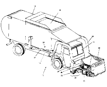
With reference to Fig. 1, there is seen a refuse collection system, generally
designated 10, embodying various aspects of the present disclosure, namely a
top
loading refuse collection vehicle 12 having a large refuse collection
compartment or
hopper 14 behind the cab 16 and having an upper opening 18 for receiving
refuse
7
CA 2982790 2017-10-18
and including a lift mechanism 20, an intermediate refuse collection container
22,
and a mounting system 24 (better seen in Figs. 10, 11A and 11B).
The lift mechanism 20 includes a pair of lift arms 26 pivotally attached to
opposite sides of the body of the collection vehicle 12, such that the lift
arms 26 carry
the mounting system 24. An actuator 28 is pivotally attached to each lift arm
26 for
moving the lift arms 26 between a first position, in which the intermediate
container is
carried upright in front of the collection vehicle 12 (as shown in Fig. 1),
and a second
position in which the intermediate container 22 is inverted for dumping its
contents into
the opening 18 of the hopper 14 (not shown).
As described in greater detail below, the mounting system 24 is convertible to
permit its use with either intermediate collection containers that have fork
receivers (not
shown in Fig. 1), or intermediate collection containers that do not have such
fork
receivers (such as the intermediate collection container described herein).
The
mounting system 24 is pivotally mounted to the ends of the lift arms 26, with
an actuator
30 interposed between each lift arm 26 and a pivot arm 32 associated with the
mounting
system 24 for rotating the mounting system 24 between a first, forward facing
position
(in which forks associated with the mounting system would extend forwardly for
insertion and receipt in the fork receivers of an intermediate container) and
a second
generally-upward facing position (in which forks associated with the mounting
system
would extend generally vertically for storage or during vehicle movement in
the absence
of an intermediate container).
The intermediate container 22 comprises a front wall 34, a rear wall 36,
opposed
sidewalls 38, 40, and a bottom wall 42 so as to define a total refuse
collection volume.
8
CA 2982790 2017-10-18
The intermediate container 22 is free of fork receivers but instead includes
one or more
mounting members 44 for non-destructive removable attachment of the collection
container 22 to the collection vehicle lift mechanism 20.
An extension assembly, generally designated 46, is positioned substantially
along
or beneath the bottom wall of the intermediate container, such as beneath the
total refuse
collection volume intermediate the front wall 34 and the rear wall 36, with a
portion of the
extension assembly 46 being movable between a first, retracted position (shown
in, e.g.,
Figs. 1-4) for storage and for dumping a primary refuse collection container
50, and a
second, extended position (shown, e.g., in Fig. 5) for engaging and releasing
the primary
3.0 refuse collection container at a location laterally spaced from the
intermediate container
22 and the refuse collection vehicle 12.
As illustrated, the extension assembly 46 includes a rigid extension member 52
and a track assembly 54 carried by the container 22 that cooperates with the
rigid
extension member 52 to allow lateral reciprocal movement of the rigid
extension
member 52 relative to the side wall 40 of the container 22. An actuator 56,
such as a
hydraulic cylinder, is provided for moving the rigid extension member 52 back
and forth
along the track 54.
As best seen in Fig. 13, the rigid extension member 52 has opposed side edges,
each of which includes a roller channel 58. The track assembly has opposed
side
frames 60, each of which carries a plurality of rollers 62 and a self-
lubricating guide
block 64, each of which is received within a respective one of the roller
channels 58. An
openable access panel 66 is provided that defines a portion of the container
bottom wall
42, such that at least a portion of the extension assembly 46 is located below
the
9
CA 2982790 2017-10-18
access panel 66.
A mounting base 68 is secured to the extension assembly 46 that is configured
for
mounting a primary refuse collection container lifter 70 thereon for engaging
and
dumping primary refuse containers into the intermediate container. Exemplary
container
lifters are shown in US 7,390,159 and US 2011/0038697, which
have the same assignee as the present application. Any desired lifter,
however,
may be used.
In keeping with another aspect of the disclosure, the intermediate
container 22 includes a plurality of spaced apart mounting members 44 for
removably
and non-destructively mounting the intermediate container 22 to lift arms 26
associated
with the lift mechanism 20 of the refuse collection vehicle 12. The mounting
members
44 extend generally rearwardly from the intermediate container 22, and are
configured
to engage mating connectors 72 (best seen in Figs. 10, 11A and 11B, and
described in
greater detail below), so as to bring the mounting members 44 and connectors
72 into
alignment as a collection vehicle 12 and the intermediate container 22 are
moved into
proximity during joinder.
As illustrated, the container mounting members 44 preferably extend at a
diverging or converging angle (a converging angle being shown) relative to the
rear wall
36 of the intermediate container 22. Preferably, the intermediate container 22
further
.. includes a brace 74 extending rearwardly intermediate the container
mounting members
44 that also provides for non-destructive removable attachment of the
intermediate
container 22 to the mounting system 24 of the collection vehicle 12.
In keeping with another aspect of the disclosure, the mounting system 24 is
Date Recue/Date Received 2023-03-13
configured so as to be convertible to permit its use with either an
intermediate collection
container having fork receivers or an intermediate collection container
without fork
receivers. To this end, the mounting system 24 includes a cross member 76 that
extends between and pivotally attaches to the lift arms 26 of the lift
mechanism 20 for
the collection vehicle 12. Spaced-apart mounting connectors 72 are fixedly
attached to
the cross member 76 (by, e.g., welding) and are configured for selective and
non-
destructive removable attachment to either forks for lifting an intermediate
container
having fork receivers, or to the mounting members of the intermediate
container
described above, which is free of fork receivers.
As Illustrated, the mounting connectors 72 comprise mounting plates that
extend
at an acute angle relative to the axis of the cross member 76. More
specifically, the
connectors 72 extend at a diverging angle for engagement with mounting members
44
that extend rearwardly for the collection container 22 at a converging angle.
This
arrangement helps align the vehicle and intermediate container as they are
moved
toward one another. To enhance the ease and strength of the connection, each
mounting connector 72 preferably includes any suitable registration shape 70
for mating
engagement with a complementary registration shape 80 on the respective
intermediate
container mounting member 44 or container fork 82. To this end, the mounting
connectors 72, as specifically illustrated, have forward-facing saddles or
concave
recesses 70 for receiving raised circular bosses 80 that are integral with the
container
fork 82 or the mounting member 44 of the intermediate container 22. The cross
member 76 further includes an attachment point 84 on the cross member 76
intermediate the mounting connectors 72 for attachment to the brace 74 that
extends
11
Date Recue/Date Received 2023-12-06
rearwardly from the intermediate container 22.
In addition, fastening assemblies, generally designated 86, are provided for
non-
destructively and removably attaching each mounting connector 72 to a
container lift fork
82 or a mating connector 44 on the intermediate container 22. As illustrated,
the fastening
assemblies 86 are configured to attach a mounting member 44 and mounting
connector 72
together in face to face relation by means of a plate 88 and a plurality of
bolts 90 and nuts
92. The plate is generally u-shaped when viewed in cross-section, with opposed
flanges
which overlap the adjoining portions of the connectors 72 and members 44 to
enhance
rigidity when connected. The rigid connection of the intermediate container to
the cross
member by the mounting members 44 and brace 74 is believed to reduce shock and
vibration that can occur during lifting and dumping when using vehicle forks
and a standard
intermediate container having fork receivers.
As shown in Figs. 1-9 and described above, the intermediate container 22 is
removably connected to the cross member 76, which is carried between the ends
of the lift
arms 26 of the collection vehicle 12. With reference to Figs. 15-20, an
alternative means for
removably attaching the intermediate container 22 to the lift arms 26 is
shown. Specifically,
the mounting system no longer includes an elongated cross member that extends
between
the ends of the lift arms. Instead, the intermediate container 22 includes a
mounting member
100, 102 secured to each of the opposed sidewalls 38, 40 of the intermediate
container.
Each of the mounting members 100, 102 comprises an elongated arm 104 that is
welded, or otherwise permanently secured to the container sidewall 38, 40,
with each arm
104 extending rearwardly of the rear wall 36 of the container 22. Each arm 104
has
12
Date Recue/Date Received 2023-03-13
an elongated cylindrical member 106 secured generally perpendicularly thereto,
the end
of which has the pivot arm 32 secured thereto and which is rotatably mounted
to the end
of its associated lift arm 26 (as shown in Fig. 20). Due to the length of the
cylindrical
member 106 associated with mounting member 102, additional bracing 108 is
provided
to further strengthen and rigidify the structure.
In a further alternative, shown in Figs 21 and 22, each of the mounting
members
100, 102 comprises a box section 120 having a top wall, a bottom wall, and a
plurality of
side walls. The rearward portion of the elongated arms 104 extends to the rear
wall 36 of
the intermediate container 22 and forms one of the side walls of box sections
100, 102.
io The elongated cylinder 106 extends between the two box sections. The box
sections
provide for greater rigidity with a reduced total mass and are shaped without
90 bends,
thus reducing stress risers in the mounting structure. Each end of the
cylinder 106 is
rotatably mounted to the end of its associated lift arm and has a pivot arm 32
secured
thereto.
If a refuse collection vehicle that carries an intermediate container 22 that
includes
mounting members 100, 102, is to be converted to one suitable for use with
intermediate
containers having fork-receiving pockets, upon disconnecting the mounting
members
100, 102 from the ends of the lift arms 26, a cross member 76 that carries
removable
forks 82, such as that shown in Figs. 10 and 11B, may be secured between the
ends of
the lift arms 26. Alternatively, a conventional cross member having the forks
permanently
secured thereto (not shown) may be secured between the ends of the lift arms.
Through use of the mounting members 100, 102, the mounting structure is
simplified and its weight reduced. Further weight savings may be realized by
reconfiguration of the actuator 110 associated with the container lifter 70. A
single central
13
CA 2982790 2017-10-18
idler arm 112 may be substituted for two idler arm actuator used in the first
embodiment,
thus permitting the faceplate 114 of the lifter 70 to be narrower. The idler
arm 112 is
centrally mounted to the actuator and pivots on anchor lugs 116 incorporated
into and
integral with the body structure/housing of the actuator 110, thus eliminating
the support
structure that extended from the mounting base 68 of the first embodiment.
Further, by
having the mounting feet 118 of the actuator face downwardly, the mounting
base 68
may be eliminated entirely.
The access panel 66 may also be eliminated to save weight in favor a fixed
panel
secured in place by, e.g., welding to provide a water-tight seal, with access
to the
1.0 extension assembly 46 for servicing provided from underneath the
intermediate
container. To simplify servicing, the rollers 60 and the self-lubricating
guide blocks 64
may be secured to the extension member 52, rather than to the side frames 60
of the
track (best seen in Figs. 15 and 16).
The system described above thus provides for a method of refuse collection
with
.. a refuse collection vehicle that comprises non-destructively removably
attaching
intermediate container lift forks to the lift arms; lifting and dumping an
intermediate
collection container having fork receivers; non-destructively removing the
container lift
forks from the lift arms; and non-destructively removably attaching to the
lift arms an
intermediate container lacking fork receivers. This versatile arrangement
allows the
same refuse collection vehicle to be used with forks for dumping commercial
refuse
collection containers with fork receivers, such as encountered on commercial
refuse
collection routes, and then after conversion by removal of the forks and
attachment of
the intermediate collection contain, to be used for residential routes where
refuse is
14
CA 2982790 2017-10-18
collected from primary curb-side collection containers, and, if desired,
converted by to
the use forks for commercial routes, as needed by the waste hauler.
Thus, a new and unique arrangement for an intermediate refuse collection
container has been provided, offering particular versatility for emptying,
intermediate
containers not found on prior systems. The foregoing description is intended
to be
illustrative, and is not intended to limit the invention to any specific
system or device.
CA 2982790 2017-10-18