Note : Les descriptions sont présentées dans la langue officielle dans laquelle elles ont été soumises.
CA 02983733 2017-10-23
WO 2016/172669
PCT/US2016/029121
1
EXOTHERMIC REACTION WELDING MOLDS, WELD-METAL CONTAINING CARTRIDGES FOR
SUCH MOLDS, AND METHODS OF USE
BACKGROUND
1. Field of the Disclosure
[0001] The present disclosure is related to exothermic welding. More
particularly, the
present disclosure is related to exothermic welding molds, weld-metal
containing cartridges
for such molds, and methods of use.
2. Description of Related Art
[0002] The use of exothermic reaction welding is known for joining various
connectors
and/or conductors to each other such as, but not limited to, stranded wire
conductors,
ground rods, connector lugs, and others.
[0003] During such welding, it is common to employ a reusable mold that has a
reaction
chamber in fluid communication with a weld cavity, which is positioned below
the reaction
chamber. In this process, portions of the components to be welded together are
placed in
the weld cavity ¨ either before or after insertion of the weld materials.
During insertion of
the weld materials, a metal disk or plug is often placed at the bottom of the
reaction
chamber, to temporarily seal off the passageway between weld chamber from the
reaction
chamber, and an exothermic weld-metal is placed in the reaction chamber.
[0004] The weld-metal is ignited such that an exothermic reaction results in
the reaction
chamber. The weld-metal liquefies and melts the disk or plug to allow the
molten material
to flow into the weld cavity, which welds together the components within the
cavity.
[0005] The process of installing the metal disk or plug and filling the
reaction chamber with
weld-metal occurs in the field and ¨ often times ¨ in difficult conditions,
which can increase
CA 02983733 2017-10-23
WO 2016/172669
PCT/US2016/029121
2
the time necessary to form the desired welds, can result in improper welds,
and other
disadvantageous results.
[0006] Thus, it has been determined by the present disclosure that there is a
need for
molds, weld-metal containing cartridges, and methods of use that overcome,
alleviate,
and/or mitigate one or more of the aforementioned and other deleterious
effects of the
prior art.
SUMMARY
[0007] Exothermic welding molds, weld-metal containing cartridges for such
molds, and
methods of use are provided. The mold, cartridges, and methods can provide
interaction
between the cartridge's disk member with the mold, which allows the housing
member to
be withdrawn from the mold while leaving the disk member and weld-metal in
place.
[0008] In some embodiments, the interaction between the mold and the disk
member is a
rotational restraint alone, a vertical restraint alone, or combinations of
rotational and
vertical restraints.
[0009] In other embodiments, the interaction between the mold and the disk
member is an
outward pressure on the housing member and/or disk member, a shear force on
the
housing member and/or disk member, or combinations thereof.
[0010] In still other embodiments, the outward pressure on the housing member
and/or
disk member is provided without interaction between the disk member and the
mold, but
rather by the simple application of an internal pressure to the cartridge. The
internal
pressure can be applied by squeezing the walls of the cartridge and/or by
depressing a
pusher member.
[0011] The method includes dropping a weld-metal containing cartridge into a
mold so that
a protrusion of a disk member is received in an indentation of the mold;
rotating the mold
and cartridge with respect to one another so that the disk member is released
from a
CA 02983733 2017-10-23
WO 2016/172669
PCT/US2016/029121
3
housing member of the cartridge; and withdrawing the housing member from the
mold so
that disk member and the weld-metal within the cartridge remain in the mold.
[0012] An exothermic reaction welding mold is provided that includes a
reaction chamber
having a shoulder and a wall positioned above a passageway. The wall has at
least one
radially extending indentation defined therein. In some embodiments, the
radially
extending indentation further includes an undercut area.
[0013] An exothermic weld-metal containing cartridge is also provided that
includes a
housing member and a disk member. The housing member has a horizontal slot
depending
from a vertical slot. The disk member has a radially extending protrusion
depending
therefrom. The disk member is secured to the housing member with the radially
extending
protrusion in the horizontal slot. The disk member is removable from the
housing member
by rotation of the disk and housing members with respect to one another so
that the
extending protrusion is aligned with the vertical slot.
[0014] In some embodiments, the cartridge further includes exothermic weld-
metal in the
housing member. Additionally, the exothermic weld-metal can include an
ignition material
that is remote from the disk member.
[0015] In other embodiments, the housing member can include an upper retaining
rim
opposite the disk member and a pusher member slidably received in the housing
member.
The upper retaining rim prevents withdrawal of the pusher member from the
housing
member.
[0016] The housing member can also include a lower support rim to abut against
and
support the disk member.
[0017] A method of using exothermic reaction welding molds and cartridges is
provided.
The method includes dropping a weld-metal containing cartridge into a mold so
that a
protrusion of a disk member is received in an indentation of the mold;
rotating the mold
and cartridge with respect to one another so that the disk member is released
from a
4
housing member of the cartridge; and withdrawing the housing member from the
mold so that
disk member and the weld-metal within the cartridge remain in the mold.
[0018] In some embodiments, the rotating step includes rotating the mold and
cartridge with
respect to one another so that the protrusion is received in an undercut area
to the mold and
rotating the mold and housing member with respect to one another so that the
disk member is
released from the housing member.
[0019] In other embodiments, the withdrawing step includes pushing on a pusher
member so that
the pusher member slides in the housing member while withdrawing the housing
member from
the mold so that disk member and the weld-metal within the cartridge remain in
the mold.
[0019A] In a broad aspect, the present invention pertains to an exothermic
weld-metal containing
cartridge. There is a housing member having a horizontal slot depending from a
vertical slot, and
a disk member having a radially extending protrusion depending therefrom. The
disk member is
secured to the housing member with the radially extending protrusion in the
horizontal slot and
extends outward of the housing member. The disk member is removable from the
housing
member by rotation of the disk and housing members with respect to one
another, so that the
extending protrusion is aligned with the vertical slot.
[0019B] In a further aspect, the present invention provides an exothermic weld-
metal containing
cartridge comprising a housing member having a horizontal slot depending from
a vertical slot.
A disk member has a radially extending protrusion depending therefrom, the
disk member being
secured to the housing member with the radially extending protrusion in the
horizontal slot. The
disk member is removable from the housing member by rotation of the disk and
housing
members with respect to one another, so that the extending protrusion is
aligned with the vertical
slot. There is provided exothermic weld-metal in the housing member.
[0019C] In a still further aspect, the present invention embodies a method of
using welding molds
and cartridges comprising dropping a cartridge into a mold, the cartridge
including a disk member
removably connected to a housing member with a weld-metal disposed therein,
and interacting a
portion of the mold with a portion of the disk member to disconnect the disk
member from the
CA 2983733 2019-01-29
=
4a
housing member. The housing member is withdrawn from the mold so that the disk
member and
the weld-metal within the cartridge remain in the mold.
10019D1 Still further, the present invention provides a method of using
welding molds and
cartridges comprising dropping a cartridge into a mold. The cartridge includes
a disk member
removably connected to a housing member with a weld-metal disposed therein.
The disk member
is removed from the housing member while the cartridge is in the mold. The
housing member is
withdrawn from the mold so that the disk member and the weld-metal within the
cartridge remain
in the mold.
[0019E] Yet further, the present invention provides an exothermic reaction
welding mold
comprising a reaction chamber having a shoulder and a wall positioned above a
passageway. The
wall has at least one radially extending indentation defined so as to not
extend through the wall to
an exterior of the reaction chamber.
[0020] The above-described and other features and advantages of the present
disclosure will be
appreciated and understood by those skilled in the art from the following
detailed description,
drawings, and appended claims.
CA 2983733 2019-01-29
4b
BRIEF DESCRIPTION OF THE DRAWINGS
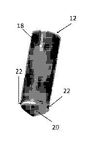
[0021] FIG. 1 is top view of an exemplary embodiment of an exothermic reaction
welding
mold according to the present disclosure;
[0022] FIG. 2A is top perspective view of the mold of FIG. 1 taken along lines
2-2;
[0023] FIG. 2B is side view of the mold of FIG. 1 taken along lines 2-2;
[0024] FIG. 3 is a bottom perspective view of an exemplary embodiment of a
weld-metal
containing cartridge for use with the mold of FIG. 1;
[0025] FIG. 4 is a side perspective view of the cartridge of FIG. 3;
[0026] FIG. 5 is a bottom perspective view of a housing member of the
cartridge of FIG. 3;
CA 2983733 2019-01-29
CA 02983733 2017-10-23
WO 2016/172669
PCT/US2016/029121
[0027] FIG. 6 is a top view of a removable disk member of the cartridge of
FIG. 3;
[0028] FIGS. 7A-7D illustrate an exemplary embodiment of a method of using the
mold of
FIG. 1 with the cartridge of FIG. 3;
[0029] FIG. 8 is top view of an alternate exemplary embodiment of an
exothermic reaction
welding mold according to the present disclosure;
[0030] FIG. 9A is top perspective view of the mold of FIG. 8 taken along lines
9-9;
[0031] FIG. 98 is side view of the mold of FIG. 8 taken along lines 9-9;
[0032] FIG. 10 is a perspective view of an alternate exemplary embodiment of a
weld-metal
containing cartridge for use with the mold of FIG. 8;
[0033] FIG. 11 is a disassembled perspective view of the cartridge of FIG. 10;
[0034] FIGS. 12A-12D illustrate an exemplary embodiment of a method of using
the mold of
FIG. 8 with the cartridge of FIG. 10;
[0035] FIG. 13 is a bottom perspective view of an alternate exemplary
embodiment of a
weld-metal containing cartridge according to the present disclosure;
[0036] FIG. 14 is a sectional view of the cartridge of FIG. 13;
[0037] FIG. 15 is a partially disassembled view of the cartridge of FIG. 13;
[0038] FIG. 16 is a sectional view of the cartridge of FIG. 13 in use with
another exemplary
embodiment of an exothermic reaction welding mold according to the present
disclosure;
[0039] FIG. 17 is a sectional view of the mold of FIG. 16 after removal of the
cartridge;
CA 02983733 2017-10-23
WO 2016/172669
PCT/US2016/029121
6
[0040] FIG. 18 is a top view of the mold of FIG. 16;
[0041] FIG. 19 is a top perspective sectional view of an alternate exemplary
embodiment of
the cartridge of FIG. 13;
[0042] FIG. 20 is a partially disassembled view of the cartridge of FIG. 19;
[0043] FIG. 21 is a bottom perspective sectional view of an alternate
exemplary
embodiment of a weld-metal containing cartridge according to the present
disclosure;
[0044] FIG. 22 is a top perspective sectional view of the cartridge of FIG. 21
in use with
another exemplary embodiment of an exothermic reaction welding mold according
to the
present disclosure;
[0045] FIG. 23 is a magnified sectional view of the cartridge and mold of FIG.
22;
[0046] FIG. 24 is a partially disassembled view of the cartridge of FIG. 21;
[0047] FIG. 25 is a bottom perspective sectional view of an alternate
exemplary
embodiment of a weld-metal containing cartridge according to the present
disclosure;
[0048] FIG. 26 is a partially disassembled view of the cartridge of FIG. 25;
[0049] FIG. 27 is a sectional view of the cartridge of FIG. 25 in use with
another exemplary
embodiment of an exothermic reaction welding mold according to the present
disclosure;
[0050] FIG. 28 is a bottom perspective sectional view of an alternate
exemplary
embodiment of a weld-metal containing cartridge according to the present
disclosure;
[0051] FIG. 29 is a partially disassembled view of the cartridge of FIG. 28;
CA 02983733 2017-10-23
WO 2016/172669
PCT/US2016/029121
7
[0052] FIG. 30 is a top perspective sectional view of an alternate exemplary
embodiment of
a weld-metal containing cartridge according to the present disclosure in use
with another
exemplary embodiment of an exothermic reaction welding mold according to the
present
disclosure;
[0053] FIG. 31 is a bottom perspective sectional view of the cartridge of FIG.
30;
[0054] FIG. 32 is a side perspective sectional view of an alternate exemplary
embodiment of
a housing member according to the present disclosure;
[0055] FIG. 33 is a sectional view of the housing member and removable disk
member of
FIG. 32 in use with a mold;
[0056] FIG. 34 is a bottom perspective sectional view of an alternate
exemplary
embodiment of a weld-metal containing cartridge according to the present
disclosure;
[0057] FIG. 35 is a bottom perspective sectional view of an alternate
exemplary
embodiment of the cartridge of FIG. 34;
[0058] FIG. 36 is a bottom perspective sectional view of an alternate
exemplary
embodiment of a weld-metal containing cartridge according to the present
disclosure;
[0059] FIG. 37 is a partially disassembled view of the cartridge of FIG. 36.
DESCRIPTION
[0060] Generally, the exothermic welding molds, weld-metal containing
cartridges for such
molds, and methods of use are provided. The mold, cartridges, and methods can
provide
interaction between the cartridge's disk member with the mold, which allows
the housing
member to be withdrawn from the mold while leaving the disk member and weld-
metal in
place.
CA 02983733 2017-10-23
WO 2016/172669
PCT/US2016/029121
8
[0061] In the embodiments of FIGS. 1-7D, 13-18, and 19-20, respectively, the
interaction
between the mold and the disk member is a combination of both a rotational
restraint and a
vertical restraint alone.
[0062] In the embodiments of FIGS. 8-12D, 25-27, and 28-29, respectively, the
interaction
between the mold and the disk member is a rotational restraint only.
[0063] In the embodiment of FIGS. 21-24, the interaction between the mold and
the disk
member is a vertical restraint only.
[0064] In the embodiment of FIGS. 30-31, the interaction between the mold and
the disk
member provides an outward pressure on the housing member and/or disk member,
a
shear force on the housing member and/or disk member, or combinations thereof.
[0065] Contrary to the embodiments of FIGS. 1-31 that provide interaction
between the
mold and the disk member, the embodiments of FIGS. 32-37 require no such
interaction.
[0066] Rather in the embodiments of FIGS. 32-37, the weld-metal containing
cartridges are
configured so that outward pressure on the housing member and/or disk member
is applied
by a simple application of an internal pressure to the cartridge. The internal
pressure can be
applied by squeezing the walls of the cartridge as in the embodiments FIGS. 32-
33, 34, and
35, respectively, and/or by depressing a pusher member as in the embodiment of
FIGS. 36-
37.
DETAILED DESCRIPTION
[0067] Referring to the drawings and in particular to FIGS. 1, 2A, and 2B, an
exemplary
embodiment of an exothermic reaction welding mold according is shown and is
generally
referred to by reference numeral 10. Additionally, an exemplary embodiment of
a weld-
metal containing cartridge for use with the mold of FIG. 1 is shown and is
generally referred
to by reference numeral 12 is shown in FIGS. 3-6.
CA 02983733 2017-10-23
WO 2016/172669
PCT/US2016/029121
9
[0068] Mold 10 and cartridge 12 are described in detail below with
simultaneous reference
to FIGS. 1-6. Generally, mold 10 includes one or more radially extending
indentations 14
and one or more undercut areas 16 (two shown of each). Cartridge 12 includes a
housing
member 18 and a removable disk member 20, which includes one or more radially
extending protrusions 22 depending therefrom.
[0069] Cartridge 12 can be filled with exothermic weld-metal 24 of any
composition
sufficient to weld desired components to one another. In some embodiments,
weld-metal
24 is in powdered form. Of course, it is contemplated by the present
disclosure for weld-
metal 24 to have any desired form such as, but not limited to, a single solid
form, multiple
solid portions, and combinations of solid and powdered portions.
[0070] Advantageously, indentations 14 are configured to receive protrusions
22 of
cartridge 12 when the cartridge is placed into mold 10. Then, upon rotation of
mold 10 and
cartridge 12 with respect to one another, undercut areas 16 are configured to
receive and
engage protrusions 22.
[0071] Cartridge 12 includes horizontal slots 26 and vertical slots 28. Disk
member 20 is
received in an inner dimension of housing member 18 with protrusions 22
received in
horizontal slots 26. In this position, disk member 20 is removably secured to
housing
member 18 by protrusions 22 with the protrusions acting in a manner similar to
bayonet-
type connections.
[0072] Once protrusions 22 are engaged in areas 16, further rotation of
cartridge 12
releases housing member 18 from disk member 20 by rotating the disk member
with
respect to the housing member until the protrusions are free of horizontal
slots 26 and are
aligned with vertical slots 28. After protrusions 22 are aligned with vertical
slots 28, housing
member 18 can be withdrawn from mold 10 with disk member 20 being retained in
position
in the mold 10.
[0073] It should be recognized that cartridge 12 is described above by way of
example as
having disk member 20 in an inner dimension of housing member 18 so that
protrusions 22
CA 02983733 2017-10-23
WO 2016/172669
PCT/US2016/029121
serve two functions, namely removably securing the disk member to the housing
member
and extending outward from the cartridge for receipt in and engagement with
indentations
14 and undercut areas 16, respectively. Of course, it is contemplated by the
present
disclosure for disk member 20 to be secured to an outer dimension of housing
member 18
via a first connection (not shown) such as a threaded or other rotation
releasable
connection in a manner that allows protrusions 22 to serve only a single
functions, namely
removably securing the disk member to the housing member and extending outward
from
the cartridge for receipt in and engagement with indentations 14 and undercut
areas 16,
respectively.
[0074] As housing member 18 is withdrawn from mold 10, weld-metal 24 is
released from
the housing member and remains on disk member 20 in the desired position
within mold
10. Thus, mold 10 and cartridge 12 are configured so that protrusions 22 of
disk member 20
are retained both rotationally and vertically in the mold, allowing easy
withdrawal of
housing member 18.
[0075] Simply stated, mold 10 and cartridge 12 provide a system to install and
secure disk
in the desired position in the mold and fill the mold with weld-metal 24 in a
simple and
repeatable manner. Additionally, cartridge 12 can prevent or at least mitigate
exposure of
weld-metal 24 to moisture before use.
[0076] Returning again to FIGS. 1, 2A, and 2B, mold 10 includes a first
portion 30 and a
second portion 32 that, when positioned adjacent one another define a reaction
chamber
34 having an open top 36 and a passageway 38 that leads to a weld chamber (not
shown).
First and second portions 30, 32 are then held in the desired position in any
desired method
such as using clamps known in the art.
[0077] It should be recognized that first and second portions 30, 32 are
illustrated for ease
of description as being symmetrical mirror images of one another. Of course,
it is
contemplated by the present disclosure for portions 30, 32 to have any desired
configuration. Thus in the illustrated embodiment, the part line between first
and second
portions 30, 32 is positioned so that a portion of indentations 14 are present
in each
CA 02983733 2017-10-23
WO 2016/172669
PCT/US2016/029121
11
portion, while one undercut area 16 is in present in only one portion and the
other undercut
area 16 is in present in only the other portion.
[0078] Reaction chamber 34 has a shoulder 40 that receives disk member 20 and
a wall 42
depending from the shoulder. In the illustrated embodiment, indentation 14 and
undercut
area 16 are positioned in wall 42 so that protrusions 22 are received in the
indentations and
can be received in the undercut areas when disk member 20 is received on
shoulder 40.
[0079] Thus, mold 10 and cartridge 12 are illustrated having disk 20 and
shoulder 40 with
corresponding shapes. In the illustrated embodiment, disk 20 has a tapered
bottom surface
with an angle of about 120 degrees, while shoulder 40 has a tapered upper
surface with an
angle of about 120 degrees. Of course, it is contemplated by the present
disclosure for disk
20 and shoulder 40 to have any desired corresponding or non-corresponding
shape.
[0080] Mold 10 and more specifically first and second portions 30, 32 are, in
some
embodiments formed from graphite. Cartridge 12, in some embodiments, includes
housing
member 18 formed of materials such as, but not limited to, polymers including
thermoplastic and thermoset polymers, fibers materials, paper or paper
composites,
ceramic, porcelain, graphite, metals including aluminum or aluminum alloys,
and any other
material having the desired oxygen and/or moisture protection properties,
while disk
member 20 is formed from metal such, as but not limited to, steel, copper,
aluminum, and
others.
[0081] In some embodiments, cartridge 12 can include one or more identifying
indicia that
allow the user to visually identify one or more attributes of the cartridge
such as, but not
limited to, catalog number, product number, the cartridge size, mold type,
weld-material
type, serial number, barcode, and others. The identifying indicia can include
a color of
housing member 18 and/or disk member 20, a label on the and/or disk member,
and other
indicia.
[0082] Disk member 20 is sufficient to temporarily seal off passageway 38
between reaction
chamber 34 and the weld chamber to allow weld-metal 24, once ignited in the
reaction
CA 02983733 2017-10-23
WO 2016/172669
PCT/US2016/029121
12
chamber, to reach a desired temperature and/or reaction state before melting
through the
disk member and passing, under the effect of gravity, through the passageway
into the weld
chamber.
[0083] In some embodiments, weld-metal 24 includes an ignition material 44.
During
assembly of cartridge 12, ignition material 44 is, preferably placed into
housing member 18
before weld-metal 24 so that the ignition material is remote or opposite disk
member 20. In
this manner, ignition material 44 ¨ after removal of housing member 18¨ is
accessible to
the user through open top 36 of mold 10.
[0084] It should be recognized that cartridge 12 and mold 10 can have any
desired number
of protrusions 22 and indentations 14/undercut areas 16 sufficient to retain
(rotationally
and vertically) disk member 20 in the mold. Moreover, it should be recognized
that
cartridge 12 and mold 10 are described by way of example as having protrusions
22 on disk
member 20 and indentations 14 on the mold. Of course, it is contemplated by
the present
disclosure for mold 14 to have protrusions and disk member 20 to have
indentions sufficient
to retain (rotationally and vertically) disk member 20 in the mold.
[0085] Referring now to FIGS. 7A-7D, a method of using mold 10 and cartridge
12 is
described and is generally referred to by reference numeral 50.
[0086] Method 50 includes a first or drop-in step 52 where cartridge 12 is
inserted vertically
through open top 36 of mold 10. During drop-in step 52, cartridge 12 is placed
in mold 10
so that protrusions 22 are received in indentations 14, the bottom surface of
disk member
20 is supported by shoulder 40 of the mold, and the disk member covers
passageway 38 at
the bottom of reaction chamber 34.
[0087] Method 50 further includes a second or protrusion-locking step 54 where
protrusions 22 are locked to mold 10. During protrusion-locking step 54,
cartridge 12 is
rotated with respect to mold 10 until protrusions 22 are received in undercut
areas 16 of
the mold.
CA 02983733 2017-10-23
WO 2016/172669
PCMJS2016/029121
13
[0088] It should be recognized that protrusion-locking step 54 is described by
way of
example only as rotating cartridge 12 with respect to mold 10. Of course, it
is contemplated
by the present disclosure for step 54 to include any rotation of mold 10 and
cartridge 12
with respect to one another.
[0089] The rotation of cartridge 12 with respect to mold 10 is continued in
step 54 until
contact and/or the friction between protrusions 22 and undercut areas 16 is
greater than
the friction between the protrusions and horizontal slots 26 in housing member
18. At this
point, method 50 includes a third or disk-removal step 56.
[0090] During disk-removal step 56, cartridge 12 is rotated ¨with protrusions
22 held in
place by undercut areas 16, so that the protrusions slide within horizontal
slots 26 until the
protrusions are aligned with vertical slots 28.
[0091] Simply stated, protrusion-locking step 54 and disk-unlocking step 56
serve to secure
disk member 20 in mold 10 and to unlock or free the disk member from housing
member
18.
[0092] Method 50 further includes a fourth or housing-removal step 58. During
housing-
removal step 58, housing member 18 is lifted from mold 10 such that
protrusions 22 slide
vertically through slots 28 of the housing member¨ leaving disk member 20 in
place in the
mold and allowing weld-metal 24 to release and/or flow from the housing member
into
reaction cavity 34.
[0093] In embodiments where cartridge 12 weld-metal 24 includes ignition
material 44, the
ignition material ¨ after removal of housing member 18 during step 58¨ is
accessible to the
user through open top 36 of mold 10.
[0094] Alternate exemplary embodiments of an exothermic reaction welding mold
110, a
weld-metal containing cartridge 112, and method 150 according to the present
disclosure
are described with simultaneous reference to FIGS. 8, 9A-9B, 10-11, and 12A-
12D. Here,
component parts performing similar and/or analogous functions to those
discussed above
CA 02983733 2017-10-23
WO 2016/172669
PCT/US2016/029121
14
are labeled in multiples of one hundred and various elements that may or may
have not
been changed have been omitted for purposes of brevity.
[0095] Mold 110 and cartridge 112, much like mold 10 and cartridge 12
discussed above,
include one or more radially extending indentations 114 and a housing member
118 and a
removable disk member 120, which includes one or more radially extending
protrusions 122
depending therefrom. However, mold 110 lacks the undercut areas 16 discussed
above
with respect to mold 10.
[0096] Indentations 114 are configured to receive protrusions 122 of cartridge
112 when
the cartridge is placed into mold 110. Then, upon rotation of mold 110 and
cartridge 112
with respect to one another, indentations 114 engage protrusions 122 to
prevent rotation
of disk member 120 with respect to housing member 118.
[0097] Cartridge 112 includes horizontal slots 126 and vertical slots 128.
Disk member 120
is received in an inner dimension of housing member 118 with protrusions 122
received in
horizontal slots 126. In this position, disk member 120 is removably secured
to housing
member 118 by protrusions 122 with the protrusions acting in a manner similar
to bayonet-
type connections.
[0098] Once protrusions 122 are received in indentations 114, rotation of
cartridge 112
releases housing member 118 from disk member 120 by rotating the disk member
with
respect to the housing member until the protrusions are free of horizontal
slots 126 and are
aligned with vertical slots 128. After protrusions 122 are aligned with
vertical slots 128,
housing member 118 can be withdrawn from mold 110.
[0099] Thus, mold 110 and cartridge 112 are configured so that protrusions 122
of disk
member 120 are retained rotationally in the mold, allowing easy release of the
disk member
from the housing member. However since disk member 120 is not retained with
respect to
vertical movement in mold 110, cartridge 112 further includes a pusher member
118-1 for
weld-metal 124 within housing member 118.
CA 02983733 2017-10-23
WO 2016/172669
PCMJS2016/029121
[00100] Pusher member 118-1 is slidably positioned in housing member 118 in
a
position opposite disk member 120. Once protrusions 122 of disk member 120 has
been
released from horizontal slot 126 and are aligned with vertical slot 128,
downward pressure
on pusher member 118-1 can be used to push weld-metal 124 from the housing
member
will keeping the disk member in place in mold 110.
[00101] In some embodiments, housing member 118 can include an upper
retaining
ring 118-2 to preview inadvertent withdrawal of pusher member 118-1 from the
upper
edge. Rather, retaining ring 118-2 can ensure that pusher member 118-1 can
only be slid
within housing member 118 towards disk member 120 after protrusions 122 of the
disk
member have been aligned with vertical slots 128.
[00102] In this manner and similar to the embodiment discussed above, as
housing
member 118 is withdrawn from mold 110 and pressure is applied to pusher member
118-1,
weld-metal 124 is released from the housing member and remains on disk member
120 in
the desired position within mold 110.
[00103] It should be recognized that cartridge 112 is described above by
way of
example as having disk member 120 in an inner dimension of housing member 118
so that
protrusions 122 serve two functions, namely removably securing the disk member
to the
housing member and extending outward from the cartridge for receipt in
indentations 114.
Of course, it is contemplated by the present disclosure for disk member 120 to
be secured
to an outer dimension of housing member 118 via a first connection (not shown)
such as a
threaded or other rotation releaseable connection in a manner that allows
protrusions 122
to serve only a single function, namely removably securing the disk member to
the housing
member and extending outward from the cartridge for receipt in indentations
114.
[00104] Referring now to FIGS. 12A-12D, a method of using mold 110 and
cartridge
112 is described and is generally referred to by reference numeral 150.
[00105] Method 150 includes a first or drop-in step 152 where cartridge 112
is
inserted vertically through open top 136 of mold 110. During drop-in step 152,
cartridge
CA 02983733 2017-10-23
WO 2016/172669
PCT/US2016/029121
16
112 is placed in mold 110 so that protrusions 122 are received in indentations
114, the
bottom surface of disk member 120 is supported by shoulder 140 of the mold,
and the disk
member covers passageway 138 at the bottom of reaction chamber 134.
[00106] In the illustrated embodiment, indentations 114 positioned in wall
142 so
that protrusions 122 are received in the indentations when disk member 120 is
received on
shoulder 140.
[00107] Method 150 lacks the second or protrusion-locking step 54 discussed
above.
Rather, method 150 merely includes a third or disk-removal step 156 in which
cartridge 112
is rotated ¨ with protrusions 122 held in place by indentations 114, so that
the protrusions
slide within horizontal slots 126 until the protrusions are aligned with
vertical slots 128. In
this manner, disk-unlocking step 156 serves to unlock or free disk member 120
from housing
member 118.
[00108] Method 150 further includes a fourth or housing-removal step 158.
During
housing-removal step 158, housing member 118 is lifted from mold 110 while
downward
pressure is applied to pusher member 118-1 such that protrusions 122 slide
vertically
through slots 128 of the housing member ¨ leaving disk member 120 in place in
the mold
and allowing weld-metal 124 to be pushed from and/or flow from the housing
member into
reaction cavity 134.
[00109] Alternate exemplary embodiments of a weld-metal containing
cartridge 312
and an exothermic reaction welding mold 310 according to the present
disclosure are
described with simultaneous reference to FIGS. 13-18. Component parts
performing similar
and/or analogous functions to those discussed above are labeled in multiples
of three
hundred and various elements that may or may have not been changed have been
omitted
for purposes of brevity.
[00110] Cartridge 312 includes housing member 318 and disk member 320 with
weld-
metal 324 therein. Housing and disk member are removably connected to one
another by
CA 02983733 2017-10-23
WO 2016/172669
PCT/US2016/029121
17
way of protrusions 322, horizontal slots 326, and vertical slots 328 in a
manner similar to
that disclosed above with respect to FIGS. 3-6.
[00111] Cartridge 312 further includes a seal 360 that is secured to a rim
362 of
housing member 318. Seal 360 is, for example, an o-ring or other sealing
member that,
when housing and disk members 318, 320 are connected to one another forms a
seal
between the disk member and rim 362. In some embodiments, seal 360 forms a
hermetic
seal that prevents the egress of water and moisture into weld-metal 324.
[00112] Additionally, cartridge 312 includes a separate area 364 opposite
disk
member 320, where the separate area is sufficient to store an ignition
material 344 separate
from weld-metal 324. Preferably, separate area 364 is sealed before use by a
removable
cap 366. In this manner, cartridge 318 is configured so that after providing
weld-metal 324
into mold 310, ignition material 344 can be provided either onto the weld
metal (not
shown) or, alternately onto mold lid 368 as shown in FIG. 17.
[00113] Mold 310 includes indentations 314 and undercut areas 316 that
receive
protrusions 322 of disk member 320 in a manner similar to that disclosed above
with
respect to FIGS. 3-6. Here, undercut areas 316 have a preferably rotational
area 370 as
shown in FIG. 18. Without wishing to be bound by any particular theory,
undercut areas 316
with rotational area 370 provides increased clearance with the mold 310, which
can assist
the user during cleaning of slag and/or unused weldament between uses.
[00114] Further, the rotational shape of areas 370 have been found by the
present
disclosure to ease in manufacture of mold 310 by allowing the areas to be
easily undercut
into the mold using a circular cutting blade (not shown).
[00115] It should be recognized that cartridge 312 is illustrated with
respect to FIGS.
13-18 by way of example in use with mold 310 that includes undercuts 316¨
namely to
remove disk member 320 using both vertical and rotational interactions. Of
course, it is
contemplated by the present disclosure for cartridge 312 to find equal use
with molds such
as those illustrated in FIGS. 7A-9A ¨ namely to remove disk member 318 using
only
CA 02983733 2017-10-23
WO 2016/172669
PCT/US2016/029121
18
rotational interaction. Thus, cartridge 312 is illustrated in FIGS. 19-20
further including
pusher member 318-1 and retaining rim 318-2 in a manner similar to those
described with
respect to FIGS. 10-11 for use with this and/or other embodiments.
[00116] Other alternate exemplary embodiments of a weld-metal containing
cartridge 412 and an exothermic reaction welding mold 410 according to the
present
disclosure are described with simultaneous reference to FIGS. 21-24. Component
parts
performing similar and/or analogous functions to those discussed above are
labeled in
multiples of four hundred and various elements that may or may have not been
changed
have been omitted for purposes of brevity.
[00117] Advantageously, mold 410 and cartridge 412 are configured to allow
removal
of disk member 420 from housing member 418 using only a vertical interaction
between the
disk member and mold 410.
[00118] Here, disk member 420 has an inner dimension that forms a press fit
or
interference fit with an outer dimension of housing member 418. Although not
shown, it is
further contemplated by the present disclosure for the press fit or
interference fit between
housing member 418 and disk member 420 to be formed between an inner dimension
of
the housing member and an outer dimension of the disk member.
[00119] Mold 410 includes undercut 416 that receives protrusions 422 of
disk
member 420 in a snap fit manner. For example, mold 410 can include a lead-in
472 that
inwardly resiliently biases protrusions 422 during insertion of cartridge 412
into mold 410.
Upon protrusions 422 clearing lead in 472, protrusions 422 are received in
undercut 416 in a
manner that prevents or restrains upward vertical movement of disk member 420,
which
allows the action of withdrawing housing member 418 from mold 410 to overcome
the
press fit or interference fit between housing and disk members 418, 420.
[00120] Without wishing to be bound by any particular theory, the inward
resilient
biasing protrusions 422 can be a function of the material properties and
structure of one or
more disk member 420, housing member 422, and combinations thereof.
CA 02983733 2017-10-23
WO 2016/172669
PCMJS2016/029121
19
[00121] Other alternate exemplary embodiments of a weld-metal containing
cartridge 512 and an exothermic reaction welding mold 510 according to the
present
disclosure are described with simultaneous reference to FIGS. 25-29. Component
parts
performing similar and/or analogous functions to those discussed above are
labeled in
multiples of five hundred and various elements that may or may have not been
changed
having been omitted for purposes of brevity.
[00122] Advantageously, mold 510 and cartridge 512 are configured to allow
removal
of disk member 520 from housing member 518 using only a rotational interaction
between
the disk member and mold 510.
[00123] In FIGS. 25-27, disk member 520 is illustrated having been
threadably
received on an inner dimension of housing member 518 by cooperating threads
574, 576,
respectively. Conversely, disk member 520 is illustrated having been
threadably received on
an outer dimension of housing member 518 by cooperating threads 574, 576,
respectively.
[00124] In order to facilitate the rotational restraint, disk member 520
includes one
or more non-circular surfaces 522, illustrated as flat regions and mold 510
includes a
corresponding number of non-circular mating surfaces 516, also illustrated as
flat regions.
In this manner, when cartridge 512 is inserted into mold 510 with surfaces
516, 522
adjacent one another, rotational movement imparted to housing member 518 is
not
translated to disk member 520, but rather results in cooperating threads 574,
576
unthreading from one another.
[00125] Although not shown in FIGS. 25-29, it is contemplated by the
present
disclosure for cartridge 512 to include a seal secured to housing member 518,
where the
seal can form a hermetic seal that prevents the egress of water and moisture
into weld-
metal 524.
[00126] Other alternate exemplary embodiments of a weld-metal containing
cartridge 612 and an exothermic reaction welding mold 610 according to the
present
CA 02983733 2017-10-23
WO 2016/172669
PCMJS2016/029121
disclosure are described with simultaneous reference to FIGS. 30-31. Component
parts
performing similar and/or analogous functions to those discussed above are
labeled in
multiples of six hundred and various elements that may or may have not been
changed
having been omitted for purposes of brevity.
[00127] In this embodiment, the interaction between mold 610 and cartridge
612
impart an outward pressure on housing member 618 and/or disk member 620, a
shear force
on the housing member and/or disk member, or combinations thereof.
[00128] For example, disk member 620 can ¨ in some embodiments be a
pierceable
foil - that has sufficient rigidity to temporarily seal off passageway 638
between reaction
chamber 634 and the weld chamber to allow weld-metal 624, once ignited in the
reaction
chamber, to reach a desired temperature and/or reaction state before melting
through the
disk member and passing, under the effect of gravity, through the passageway
into the weld
chamber. Here, mold 610 can include elements 616 that interact with disk
member 620
during insertion of cartridge 612 into the mold so as to pierce through the
disk member the
disk member ¨ and thus separate the disk member from housing member 618.
[00129] In other embodiments, disk member 620 can be removably secured to
housing member 618. Here, elements 616 interact with housing member 618 and/or
disk
member 620 during insertion of cartridge 612 into the mold so as to separate
the disk
member from housing member 618. For example, elements 616 can apply an outward
force
on housing member 618 sufficient to deflect the housing member outwards so as
to
separate disk member 620 from the housing member.
[00130] Advantageously, the exothermic welding molds, weld-metal containing
cartridges for such molds, and methods of use of the present disclosure
provide ¨ in some
embodiments ¨ an interaction between the mold and the cartridge in a manner
that allows
for the removal of the disk member from the housing member once the housing
member is
within the mold. In some embodiments, the cartridges and molds of the present
application
use the same structure that removably secures the disk and housing members to
one
another to also allow removal of the disk member from the housing member and
to ensure
CA 02983733 2017-10-23
WO 2016/172669
PCT/US2016/029121
21
a positive fit or location of the disk member in the mold. In this manner, the
molds,
cartridges, and methods of the present application allow for an integrated
mold-cartridge
system in a simple, reliable, and repeatable manner.
[00131] Of course, it is contemplated by the present disclosure for the
exothermic
welding molds, weld-metal containing cartridges for such molds, and methods of
use of the
present disclosure to require no such interaction between the mold and the
cartridge to
assist in the removal of the disk member from the housing member.
[00132] Examples of non-interacting molds and cartridges are described in
more
detail below in which the disk member is removed from the housing member
through an
outward pressure on the housing member and/or disk member without interaction
between the disk member and the mold, but rather by the simple application of
an internal
pressure to the cartridge. The internal pressure can be applied by squeezing
the walls of the
cartridge and/or by depressing a pusher member as discussed in more detail
below.
[00133] Referring now to FIGS. 32-33, alternate exemplary embodiments of
the
housing member according to the present disclosure is shown and is generally
referred to by
reference numeral 218. Here, component parts performing similar and/or
analogous
functions to those discussed above are labeled in multiples of two hundred and
various
elements that may or may have not been changed have been omitted for purposes
of
brevity.
[00134] Housing member 218 can include a lower support rim 218-3 to abut
against
and support disk member 220 to ensure proper positioning of the disk member
with respect
to the housing member and to guide the flow of weld-metal (not shown) into the
disk
member.
[00135] After insertion of cartridge 212 into mold 210, outward pressure on
housing
member 218 and/or disk member 220 is provided without interaction between the
disk
member and the mold, but rather by the simple application of an internal
pressure to the
CA 02983733 2017-10-23
WO 2016/172669
PCT/US2016/029121
22
cartridge. In this embodiment, the internal pressure can be applied by
squeezing the walls
of housing member 218 radially inward as shown in FIG. 33.
[00136] It should be recognized that cartridge 212 is illustrated in FIGS.
32-33 as
having disk member 220 secured by a press or interference fit into an internal
dimension of
housing member 218. Of course, it is contemplated by the present disclosure
for cartridge
212, as illustrated in FIG. 34, to have disk member 220 secured by the press
or interference
fit to an external dimension of housing member 218 or for the disk member to
have the
structure as shown in FIG. 35 ¨ namely one that does not extend radially
outward beyond
housing member 218.
[00137] In each embodiment, the internal pressure applied to cartridge 212
by
squeezing the walls of housing member 218 is sufficient to overcome the
interference fit
between disk member 220 and the housing member so as to disconnect the disk
member
from the housing member. In some embodiments, it is contemplated by the
present
disclosure that the squeezing the walls of housing member 218 also acts to
deflect the
housing member a sufficient distance to disconnect disk member 220 from the
housing
member.
[00138] It should be recognized that cartridge 212 is illustrated with
respect to FIGS.
32-35 as requiring the user to apply the internal pressure by squeezing the
walls of housing
member 218. Of course, it is contemplated by the present disclosure for
cartridge 212, as
illustrated in FIGS. 36-37, to further including pusher member 218-1 and
retaining rim 218-2
in a manner similar to those described with respect to FIGS. 10-11 for use
with this and/or
other embodiments.
[00139] It should also be noted that the terms "first", "second", "third",
"upper",
"lower", and the like may be used herein to modify various elements. These
modifiers do
not imply a spatial, sequential, or hierarchical order to the modified
elements unless
specifically stated.
CA 02983733 2017-10-23
WO 2016/172669
PCT/1JS2016/029121
23
[00140] While the present disclosure has been described with reference to
one or
more exemplary embodiments, it will be understood by those skilled in the art
that various
changes may be made and equivalents may be substituted for elements thereof
without
departing from the scope of the present disclosure. In addition, many
modifications may be
made to adapt a particular situation or material to the teachings of the
disclosure without
departing from the scope thereof. Therefore, it is intended that the present
disclosure not
be limited to the particular embodiment(s) disclosed as the best mode
contemplated, but
that the disclosure will include all embodiments falling within the scope of
the appended
claims.