Sélection de la langue

Search

Sommaire du brevet 2983786 

Énoncé de désistement de responsabilité concernant l'information provenant de tiers

Une partie des informations de ce site Web a été fournie par des sources externes. Le gouvernement du Canada n'assume aucune responsabilité concernant la précision, l'actualité ou la fiabilité des informations fournies par les sources externes. Les utilisateurs qui désirent employer cette information devraient consulter directement la source des informations. Le contenu fourni par les sources externes n'est pas assujetti aux exigences sur les langues officielles, la protection des renseignements personnels et l'accessibilité.

Disponibilité de l'Abrégé et des Revendications

L'apparition de différences dans le texte et l'image des Revendications et de l'Abrégé dépend du moment auquel le document est publié. Les textes des Revendications et de l'Abrégé sont affichés :

  • lorsque la demande peut être examinée par le public;
  • lorsque le brevet est émis (délivrance).
(12) Brevet: (11) CA 2983786
(54) Titre français: TERMINATEUR DE RESEAU EN BUS
(54) Titre anglais: BUS NETWORK TERMINATOR
Statut: Accordé et délivré
Données bibliographiques
(51) Classification internationale des brevets (CIB):
  • H04L 12/40 (2006.01)
  • H04L 43/50 (2022.01)
(72) Inventeurs :
  • ESPOSITO, FREDERIC VLADIMIR (Royaume-Uni)
(73) Titulaires :
  • EATON INTELLIGENT POWER LIMITED
(71) Demandeurs :
  • EATON INTELLIGENT POWER LIMITED (Irlande)
(74) Agent: SMART & BIGGAR LP
(74) Co-agent:
(45) Délivré: 2023-02-28
(86) Date de dépôt PCT: 2016-04-27
(87) Mise à la disponibilité du public: 2016-11-03
Requête d'examen: 2021-04-26
Licence disponible: S.O.
Cédé au domaine public: S.O.
(25) Langue des documents déposés: Anglais

Traité de coopération en matière de brevets (PCT): Oui
(86) Numéro de la demande PCT: PCT/GB2016/051191
(87) Numéro de publication internationale PCT: WO 2016174428
(85) Entrée nationale: 2017-10-24

(30) Données de priorité de la demande:
Numéro de la demande Pays / territoire Date
1507495.8 (Royaume-Uni) 2015-04-30

Abrégés

Abrégé français

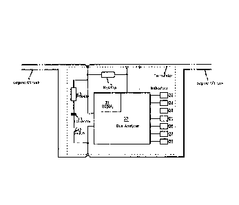
La présente invention concerne un terminateur amélioré de réseau en bus, (4) et des réseaux en bus et segments/jonctions de réseau en bus associés (1), et comportant un terminateur de réseau en bus (4) comprenant une fonctionnalité de terminaison de réseau et un analyseur de diagnostic (2) et le degré de fonctionnalité de diagnostic prévue à l'intérieur du terminateur (4) pouvant ensuite, comme pour le terminateur lui-même, être prévu sous la forme d'une caractéristique inhérente du segment/de la jonction (1), et par conséquent, du réseau en bus également, et pouvant comporter une fonctionnalité de diagnostic limitée, simple mais convenablement efficace et pouvant être adaptée intrinsèquement de manière économique pour l'analyse de bus lors de la mise en service, et/ou de la phase déploiement initial.


Abrégé anglais

The present invention provides for an improved network bus terminator (4), and related bus networks and bus network segments/trunks (1 ), and comprising a bus network terminator (4) including bus network termination functionality and a diagnostic analyser (2) and wherein the degree of diagnostic functionality provided within the terminator (4) can then, as with the terminator itself, be provided as an inherent feature of the segment/trunk (1 ), and thus also the bus network, and can comprise limited, simple but suitably effective diagnostic functionality, and which can be inherently suited to bus analysis during a commissioning, and/or initial deployment, phase and be provided in a cost-effective manner.

Revendications

Note : Les revendications sont présentées dans la langue officielle dans laquelle elles ont été soumises.


7
Claims
1. A bus network terminator having a termination functionality for a bus
network, the
bus network terminator comprising:
a diagnostic analyzer configured to:
identify whether data is present on a segment of the bus network, and
identify a degree of data activity and/or a direction of transmission on the
segment of the bus network; and
a line impedance terminator offering an in-line diagnostic functionality;
wherein the diagnostic analyzer and the line impedance terminator are
integrated in a bus device of the bus network; and
wherein the bus network terminator is configured to selectively initiate the
termination functionality responsive to a location of the bus network
terminator in the
bus network.
2. A bus network terminator as claimed in claim 1, and configured to provide
for analysis
of a segment/trunk/line on-which it is located.
3. A bus network terminator as claimed in claim 2, wherein the said basic
information
comprises one or more of segment voltage, segment traffic and/or segment
integrity.
4. A bus network terminator as claimed in claim 1, wherein the diagnostic
analyzer
comprises a basic, low-power microprocessor.
5. A bus network terminator as claimed in claim 4, wherein the microprocessor
exhibits
basic required electronics, to provide the required basic level of bus
analysis.
6. A bus network terminator as claimed in claims 1, wherein the diagnostic
analyzer is
configured to analyse a trunk voltage condition.
6526196
Date Recue/Date Received 2021-04-26

8
7. A bus network terminator as claimed in claim 6, wherein the said diagnostic
analyzer
is configured to diagnose one or more of a high voltage condition, low voltage
condition, a current condition, noise condition and/or unstable condition.
8. A bus network terminator as claimed in claim 1, wherein the diagnostic
analyzer is
configured to determine any one or more of data signal amplitude; data signal
width;
and signal stability/jitter.
9. A bus network terminator as claimed in claim 1 including an additional
short-to-shield
indication.
10. A bus network terminator as claimed in claim 1, and configured for
indication of loss
of isolation.
11. A bus network terminator as claimed in claim 10, and configured for
indication of an
impedance within a range from a few 100K0 to a short circuit condition.
12. A bus network terminator as claimed in claim 1 and including a user
interface
comprising an audio and/or visual output.
13. A bus network terminator as claimed in claim 1 and configured for remote
accessibility.
14. A bus network terminator as claimed in claim 1 including a temperature
indicator
configured to indicate terminator temperature and/or local or ambient
temperature.
15. A bus network segment including a bus network terminator having a
termination
functionality for a bus network, the segment comprising:
a diagnostic analyzer configured to:
identify whether data is present on the segment of the bus network, and
identify a degree of data activity and/or a direction of transmission on the
segment of the bus network; and
6526196
Date Recue/Date Received 2021-04-26

9
a line impedance terminator offering an in-line diagnostic functionality;
wherein the diagnostic analyzer and the line impedance terminator are
integrated in a bus device of the bus network; and
wherein the bus network terminator is configured to selectively initiate the
termination functionality responsive to a location of the bus network
terminator in the
bus network.
16. A bus network terminator as claimed in claim 1 wherein the bus network
terminator
comprises a termination resistor in series with a termination capacitor.
17. A bus network terminator as claimed in claim 16 wherein the bus network
comprises a
disconnection switch in series with the termination resistor and termination
capacitor.
18. A bus network terminator as claimed in claim 1, wherein the diagnostic
analyzer is
arranged to prove diagnostic analysis during commissioning of the bus network.
6526196
Date Recue/Date Received 2021-04-26

Description

Note : Les descriptions sont présentées dans la langue officielle dans laquelle elles ont été soumises.


CA 02983786 2017-10-24
WO 2016/174428
PCT/GB2016/051191
1
Bus Network Terminator
The present invention relates to a terminator for use in providing termination
within a
bus network and in particular, but not exclusively, to a Fieldbus H1 or
Profibus PA
terminator.
Problems such as communication errors can arise from signal reflections in bus
networks unless the ends of such networks are properly terminated. Appropriate
termination involves employment of a terminator device at each end of the bus
network and which serves to absorb signals appearing in the network so as to
prevent reflections.
In Fieldbus/Profibus networks for example, each bus segment/trunk requires two
terminators, one located at each end, and which are generally equivalent to a
lpF
capacitor and 100 fl resistor connected in series. Each terminator serves to
both
shunt the bus current so as to keep the current signals on the segment/trunk
within
the specified levels and to protect against signal reflections through
appropriate
matching with the line impedance of the segment/trunk.
Within a Fieldbus/Profibus network, the terminator can comprise a stand-alone
device, or can be incorporated into the device couplers that serve to connect
fieldbus
devices to the segment/trunk via spurs. If incorporated into a device coupler,
a
switching arrangement is also often associated with the terminator to allow
for
selective enablement of the terminator. It is only the device coupler
connected at the
end of the segment/trunk that should provide the required termination, and so
the
terminator can be enabled/disabled as required depending upon the position of
the
device coupler on the segment/trunk.
A terminator can be viewed as an essential, and therefore ever-present,
element at
the end of a Fieldbus/Profibus segment/trunk. However, currently its
functionality is
limited to one of merely offering the required termination.
Bus networks such as Fieldbus/Profibus networks often exhibit
complex/specialised
configurations for the operation/monitoring of complex, performance critical,
and
often potentially costly and hazardous industrial systems/processes.
Correspondingly complex/specialised diagnostic analysis is also then required.

CA 02983786 2017-10-24
WO 2016/174428
PCT/GB2016/051191
2
Diagnostic requirements arise both during commissioning, and subsequent
operation, of the network and a variety of sophisticated network analyser
devices are
available for providing detailed diagnostic functionality and taking into
account the
variety of potentially problematic situations that can arise. Separate
sophisticated
diagnostic devices are currently employed in relation to bus networks such as
Fieldbus/Profibus networks.
This can prove disadvantageous insofar as separate steps for obtaining,
preparing
and using known diagnostic analysers are required and the level of diagnostic
capability is often not matched, often being overly complex and highly
functional, as
compared with the level of diagnostic activity required. Inefficiencies can
therefore be
introduced into the diagnostic process and potential cost effectiveness can
also be
impaired, particularly since known diagnostic devices such as known bus
analysers
are expensive. Known bus analysers also tend to require specialist trained
staff for
their implementation and use, and which further limits their cost-
effectiveness and
can limit the ease and speed by which they can be deployed if such personnel
are
not readily available.
The present invention seeks to provide for a network bus terminator having
advantages over known such terminators and which, further, can provide for bus
networks and bus network segments/trunks having advantages over known such
networks/segments/trunks.
According to one aspect of the present invention there is provided a bus
network
terminator including bus network termination functionality and a diagnostic
analyser.
The invention can prove advantageous in so far as the degree of diagnostic
functionality provided within the terminator is then, as with the terminator
itself,
provided as an inherent feature of the segment/trunk, and thus also the bus
network.
Advantageously, the diagnostic bus analyser is arranged to provide basic
information
concerning the segment/trunk.
Such basic information can comprise, but is not limited to, one or more of
segment
voltage, segment traffic and segment integrity.
The invention advantageously therefore allows for quick-glance diagnostic
functionality without the need for a sophisticated analyser and so as to
determine

CA 02983786 2017-10-24
WO 2016/174428
PCT/GB2016/051191
3
whether any initial problems might arise. If further investigation is
required, this can
then readily be conducted by way of a separate more sophisticated analyser.
The invention can prove particularly useful during the commissioning phase of
a
segment/trunk and bus network particularly since the basic diagnostic
functionality is
inherent within each terminator which, again, form essential inherent elements
of the
segment/trunk. Immediate basic diagnosis is therefore readily possible from
even the
earliest stages in the bus network formation, in particular for basic simple
analysis
particularly suited to the network commissioning phase.
The diagnostic bus analyser of the present invention can comprise a basic, low-
power, microprocessor, with minimal required electronics, to provide the
required
basic level of bus analysis.
As non-exhaustive examples, the bus analyser can be arranged to analyse trunk
voltage, whether high, low, noisy or lacking in stability.
Further, the bus analyser can be arranged to identify whether data is present
on the
segment/trunk and, if so, the degree of data activity and/or direction of
transmission.
As further examples, the bus analyser can be arranged to determine data signal
amplitude and also data signal width and/or jitter.
As a yet further feature, an additional short-to-shield indication can be
provided. The
terminator can also incorporate a user interface that can comprise any
appropriate
audio and/or visual output, such as simple LED output device or array.
Additionally, or alternatively, the terminator can be arranged with a bus to
shield low-
impedance condition indicator, and which can be responsive to, for example,
detection of loss of isolation exhibiting impedance from values of a few
100Kil, down
to a short circuit condition.
The terminator of the invention can also comprise a bus device which can
further be
addressable from a host device, and/or be addressable from a separate system,
by
way of a wired, or wireless, connection, and if appropriate, from any required
remote
location.

CA 02983786 2017-10-24
WO 2016/174428
PCT/GB2016/051191
4
The terminator of the present invention can be incorporated into any
appropriate/required Fieldbus/Profibus segment/trunk, whether in explosive
environments or otherwise.
As will be appreciated therefore, the terminator of the invention can comprise
a line
impedance terminator offering in-line diagnostic functionality.
In particular, the basic, simple, yet effective, functionality of the analyser
of the
present invention can advantageously remain in situ, without any impact on
cost
effectiveness, and potentially as a standard fitting. This aspect of the
invention
contrasts favourably with potentially expensive, and unnecessary complex,
analysers, often fitted in a one-off manner, with only specific complex
trouble-
shooting scenarios in mind.
The invention is described further hereinafter, by way of example only, with
reference to the accompanying drawings in which:
Fig.1 is a schematic diagram of a terminator device according to an embodiment
of
the present invention;
Fig.2 is a schematic diagram similar to that of Fig. 1 of a terminator device
of the
present invention and arranged on a bus with a bus shield; and
Fig.3 is a schematic diagram of a typical fieldbus segment/trunk employing
terminator devices such as that of Figs. 1 and 2.
Turning first to Fig. 1 there is illustrated a section of a network bus 1,
such as a
trunk/segment of a Fieldbus or Profibus system and within which a terminator 4
according to an embodiment of the present invention, and so, in this example,
including diagnostic functionality, is integrally provided.
The illustrated example of the terminator 4 includes a termination resistor 10
in
series with a termination capacitor 11, both of which are likewise in series
with an
optional disconnection switch 12 which, if present, can be selectively opened
(to the
configuration as illustrated in Fig. 1) so as to disconnect the terminator 4
functionality
from the bus 4.
A shunt resistance 13 is provided for use in sensing bus current and is
discussed in
further detail in relation to Fig. 2 below.

CA 02983786 2017-10-24
WO 2016/174428
PCT/GB2016/051191
As an important feature of the present invention, the terminator 4 includes a
bus
analyser 20 which receives its power by way of a supply 21. As will be
appreciated,
the bus analyser is arranged to provide for relatively simple bus analysis
which can
be quickly and efficiently deployed, without requiring specialist
staff/personnel. The
terminator 4 can then provide for basic analysis, at any time as required, for
example, during the commissioning of the bus 1, during initial use or as part
of a
"trouble-shooting" procedure, or even during periods of regular/ irregular
control
signalling on the bus.
The result of such analysis can then be presented by way of any appropriate
form of
user interface. Various examples are illustrated with reference to Fig. 1 but
it should
be appreciate that the interface devices can be provided in any required
number and
combination. In the illustration provided by Fig. 1, examples of such devices
are, an
optical indicator 22, and audio indicator 23, a display screen 24, a radio
transmitter
25, an alternative wireless interface 26, and connector socket 28.
As will therefore be appreciated, the terminator 4 embodying the present
invention
can advantageously comprise part of the bus 1 and can be remotely accessible
as
required. Such remote accessibility can be arranged to allow for
activation/deactivation of the bus analyser 20 and/or terminator functionality
and/or
selection of the specific diagnostic check to be conducted by the analyser 20.
The
terminator 4 therefore has the inherent ability to offer at least some degree
of
diagnostic analysis useful, in particular, during commissioning of a network
bus 1
such as a Fieldbus or Profibus trunk/segment.
Fig. 2 is a schematic diagram similar to that of Fig. 1, but in which a field
side 2 of
the bus 1 is further indicated and which of course has relevance when current
is to
be sensed by the shunt resistor 13. The configuration of the shunt resistor 13
in
relation to the bus 1 within Fig. 2 is illustrated in accordance with bus-
current sensing
characteristic and this further example of the present mention is also
illustrated in
relation to a bus 1 employing a bus shield 3. In this manner, one of shield
isolation
sensing or current measuring can be provided as required.
Figure 3 is a schematic representation of a complete network segment/trunk 1
employing terminator devices such as those 4 of Figs. 1 and 2. The complete
segment/trunk 1 is illustrated with the respective terminator devices 4
located at

CA 02983786 2017-10-24
WO 2016/174428 PCT/GB2016/051191
6
each end to offer the required termination for the segment/trunk. Schematic
representations of further devices typically employed with, for example, a
Fieldbus
segment/trunk. That is, in the illustrated example, there is provided a
Distributed
Control System (DCS), or indeed some other form of controller 30, a Fieldbus
power
supply 31 for the segment/trunk 1, a power conditioner 32 arranged to
superimpose
data onto the segment/trunk supply and prevent crosstalk between adjacent, and
an
terminal device such as a field unit 33, and/or barrier 34 and/or bus isolator
35.
Of course, the present invention is not restricted to the details of the
foregoing
examples and embodiments. For example, any appropriate further termination and
bus analysis functionality can be provided as required. With regard to the
segment/trunk 1 configuration of Fig. 3, the segment/trunk can of course form
part of
any appropriate signalling network and any required number of
terminator/analysis
devices 4 of the present invention can be provided. As noted above, the
termination
functionality of such devices 4 can be selectively initiated responsive to the
location
of the device 4 on the segment/spur 1.

Dessin représentatif
Une figure unique qui représente un dessin illustrant l'invention.
États administratifs

2024-08-01 : Dans le cadre de la transition vers les Brevets de nouvelle génération (BNG), la base de données sur les brevets canadiens (BDBC) contient désormais un Historique d'événement plus détaillé, qui reproduit le Journal des événements de notre nouvelle solution interne.

Veuillez noter que les événements débutant par « Inactive : » se réfèrent à des événements qui ne sont plus utilisés dans notre nouvelle solution interne.

Pour une meilleure compréhension de l'état de la demande ou brevet qui figure sur cette page, la rubrique Mise en garde , et les descriptions de Brevet , Historique d'événement , Taxes périodiques et Historique des paiements devraient être consultées.

Historique d'événement

Description Date
Inactive : Octroit téléchargé 2023-03-01
Lettre envoyée 2023-02-28
Accordé par délivrance 2023-02-28
Inactive : Page couverture publiée 2023-02-27
Préoctroi 2022-12-05
Inactive : Taxe finale reçue 2022-12-05
Un avis d'acceptation est envoyé 2022-08-09
Lettre envoyée 2022-08-09
Un avis d'acceptation est envoyé 2022-08-09
Inactive : Approuvée aux fins d'acceptation (AFA) 2022-05-27
Inactive : Q2 réussi 2022-05-27
Inactive : CIB expirée 2022-01-01
Inactive : CIB du SCB 2022-01-01
Lettre envoyée 2021-05-05
Modification reçue - modification volontaire 2021-04-26
Exigences pour une requête d'examen - jugée conforme 2021-04-26
Modification reçue - modification volontaire 2021-04-26
Toutes les exigences pour l'examen - jugée conforme 2021-04-26
Requête d'examen reçue 2021-04-26
Représentant commun nommé 2020-11-07
Représentant commun nommé 2019-10-30
Lettre envoyée 2019-01-15
Lettre envoyée 2019-01-07
Inactive : Transferts multiples 2018-12-13
Requête pour le changement d'adresse ou de mode de correspondance reçue 2018-07-12
Inactive : CIB enlevée 2018-02-20
Inactive : Page couverture publiée 2018-01-09
Inactive : CIB attribuée 2018-01-03
Inactive : CIB enlevée 2018-01-03
Inactive : CIB en 1re position 2018-01-03
Inactive : CIB attribuée 2018-01-03
Inactive : Notice - Entrée phase nat. - Pas de RE 2017-11-06
Inactive : CIB attribuée 2017-10-31
Demande reçue - PCT 2017-10-31
Exigences pour l'entrée dans la phase nationale - jugée conforme 2017-10-24
Demande publiée (accessible au public) 2016-11-03

Historique d'abandonnement

Il n'y a pas d'historique d'abandonnement

Taxes périodiques

Le dernier paiement a été reçu le 2022-03-23

Avis : Si le paiement en totalité n'a pas été reçu au plus tard à la date indiquée, une taxe supplémentaire peut être imposée, soit une des taxes suivantes :

  • taxe de rétablissement ;
  • taxe pour paiement en souffrance ; ou
  • taxe additionnelle pour le renversement d'une péremption réputée.

Veuillez vous référer à la page web des taxes sur les brevets de l'OPIC pour voir tous les montants actuels des taxes.

Historique des taxes

Type de taxes Anniversaire Échéance Date payée
Taxe nationale de base - générale 2017-10-24
TM (demande, 2e anniv.) - générale 02 2018-04-27 2018-03-20
Enregistrement d'un document 2018-12-13
TM (demande, 3e anniv.) - générale 03 2019-04-29 2019-03-20
TM (demande, 4e anniv.) - générale 04 2020-04-27 2020-03-23
TM (demande, 5e anniv.) - générale 05 2021-04-27 2021-03-23
Requête d'examen - générale 2021-04-27 2021-04-26
TM (demande, 6e anniv.) - générale 06 2022-04-27 2022-03-23
Taxe finale - générale 2022-12-09 2022-12-05
TM (brevet, 7e anniv.) - générale 2023-04-27 2023-03-21
TM (brevet, 8e anniv.) - générale 2024-04-29 2023-12-14
Titulaires au dossier

Les titulaires actuels et antérieures au dossier sont affichés en ordre alphabétique.

Titulaires actuels au dossier
EATON INTELLIGENT POWER LIMITED
Titulaires antérieures au dossier
FREDERIC VLADIMIR ESPOSITO
Les propriétaires antérieurs qui ne figurent pas dans la liste des « Propriétaires au dossier » apparaîtront dans d'autres documents au dossier.
Documents

Pour visionner les fichiers sélectionnés, entrer le code reCAPTCHA :


Pour visualiser une image, cliquer sur un lien dans la colonne description du document. Pour télécharger l'image (les images), cliquer l'une ou plusieurs cases à cocher dans la première colonne et ensuite cliquer sur le bouton "Télécharger sélection en format PDF (archive Zip)" ou le bouton "Télécharger sélection (en un fichier PDF fusionné)".

Liste des documents de brevet publiés et non publiés sur la BDBC .

Si vous avez des difficultés à accéder au contenu, veuillez communiquer avec le Centre de services à la clientèle au 1-866-997-1936, ou envoyer un courriel au Centre de service à la clientèle de l'OPIC.


Description du
Document 
Date
(aaaa-mm-jj) 
Nombre de pages   Taille de l'image (Ko) 
Description 2017-10-24 6 282
Abrégé 2017-10-24 1 58
Dessin représentatif 2017-10-24 1 4
Dessins 2017-10-24 1 12
Revendications 2017-10-24 3 84
Page couverture 2018-01-09 1 37
Revendications 2021-04-26 3 92
Dessins 2021-04-26 1 49
Dessin représentatif 2023-01-31 1 16
Page couverture 2023-01-31 1 49
Avis d'entree dans la phase nationale 2017-11-06 1 194
Rappel de taxe de maintien due 2017-12-28 1 111
Courtoisie - Réception de la requête d'examen 2021-05-05 1 425
Avis du commissaire - Demande jugée acceptable 2022-08-09 1 554
Certificat électronique d'octroi 2023-02-28 1 2 527
Rapport de recherche internationale 2017-10-24 2 53
Demande d'entrée en phase nationale 2017-10-24 2 76
Courtoisie - Lettre d'avis à l'agent 2019-01-15 1 46
Requête d'examen / Modification / réponse à un rapport 2021-04-26 9 289
Taxe finale 2022-12-05 4 122