Note : Les descriptions sont présentées dans la langue officielle dans laquelle elles ont été soumises.
DOOR SWEEP
AND METHOD FOR
INSTALLING A DOOR SWEEP
Cross-Reference to Related Application(s)
[0001] This U.S. Patent Application is a Continuation-In-Part of United
States Patent
Application Serial No. 15/338,032, which was filed on October 28, 2016, the
entire contents of
which are incorporated herein by reference.
Field of the Invention
[0002] The present disclosure relates to a door sweep. While not limiting
of the present
invention, an aspect of the disclosure provides for a door sweep configured to
attach to a
mounting rail mounted at the bottom edge of a swinging door, door panel or the
like. The
disclosed door sweep offers an improved means for assembly to the mounting
rail.
Description of the Background and Related Art
[0003] There are numerous configurations for door sweeps that have been
employed in
the prior art.
[0004] A typical inswing, side-hinged door system utilizes a flexible
sealing member, or
door sweep, secured to the bottom edge of the door panel. The door sweep
interacts with a cap
component of the door sill or a threshold to create a barrier that discourages
external elements,
such as air, water, dirt, and debris, in an exterior environment from
migrating into an interior
environment. The exterior environment may be outside of a structure, such as a
building or
house, for example, while the interior environment may be a room within the
structure.
[0005] A door sweep often includes dual, protruding fingers that mate
with dual slots in
the bottom of the door panel. Still further, flexible fins on the fingers may
be included to provide
a friction fit with the dual slots to retain the door sweep in a desired
position on the door panel.
[0006] In instances where the door panel does not include slots, other
attachments
method may include suitable fasteners, such as adhesives, staples, or screws.
1
CA 2984306 2017-10-27
[0007] Certain door panels used in exterior, side-hinged door assemblies
employ a
different door sweep design. These door panels have a stamped steel rail with
offset edges over
which the door sweep slidably engages. The installation of door sweeps for
these door panels
involves sliding the door sweep from the proximate end of the rail to the
distal end of the rail
until the leading edge of the door sweep aligns with the distal end of the
rail. One disadvantage
to this design involves the clearance required for the door sweep to engage
the rail. Specifically,
a larger clearance results in a less effective seal between the door panel and
the rail. Moreover, a
considerable amount of force may be needed to slide the door sweep onto the
door, complicating
the assembly process.
[0008] While some solutions to one or more of the difficulties enumerated
above have
been proposed by the prior art, a need persists for improved solutions.
Summary of the Invention
[0009] The present invention addresses one or more of the deficiencies
with respect to
the prior art.
[0010] Specifically, the present invention provides a door sweep that
allows for easy
assembly to the door panel.
[0011] Another aspect of the present invention is that the door sweep
facilitates an
effective barrier to external environmental elements.
[0012] The present disclosure provides a door sweep configured to engage
a door panel
of an exterior, side-hinged door assembly having a stamped steel rail with
offset edges. The door
sweep is configured with rigid slots that engage with offset edges of the
mounting rail. Using an
assembly tool, the door sweep may be mounted to the mounting rail.
[0013] An embodiment provides a door sweep designed to mate with a door
panel
mounting rail that allows for easy assembly to the door panel while
facilitating an effective
barrier to external environmental elements. In this embodiment, opposing,
inwardly oriented
rigid slots of the door sweep are configured to engage offset edges of a
mounting rail. A flexible
bulb is co-extruded on the top surface of the sweep to act as a primary seal
between the door
panel and the door sweep. Co-extruded flexible ribs on the inner faces of the
rigid slots mate
with the top and bottom surfaces of the offset rail edges to prevent migration
of air and water
2
CA 2984306 2017-10-27
from the exterior to the interior of the building when the door panel is
closed, as well as to
facilitate retention of the sweep on the rail. Upwardly projecting rigid
fingers extend from the
base of the door sweep towards the bottom edge of the door panel to maintain a
substantially
parallel orientation of the base to the bottom of the door panel. The base
includes a co-extruded,
resilient central segment to allow extension of the base during assembly. The
edges of the door
sweep include rigid, hooked fingers for receiving a mounting tool.
[0014] The resilient sealing members extending from the bottom of the
door sweep may
embody various configurations that interact with the cap component of the door
sill or threshold
to create a barrier that can resist infiltration of external elements such as
air, water, dirt and
debris from the exterior environment into the interior of the building. These
elements may be
symmetric about the vertical centerline of the door sweep profile to allow for
non-oriented
attachment.
[0015] The mounting of the door sweep to the mounting rail may involve
mating one of
the rigid slots of the door sweep with one offset edge of the mounting rail
substantially along the
length of each component. An assembly tool may then be used to grab the hooked
finger on the
non-engaged edge of the door sweep. Using the face of the door panel as a
fulcrum, the tool is
rotated towards the top edge of the door panel. This action causes the
resilient central segment of
the door sweep to extend and allow the second slot of the door sweep to extend
past the second
offset edge of the mounting rail. As tool rotation continues, the second slot
of the door sweep
aligns with the second offset edge of the mounting rail. As the tool is
released, the resilient
central segment of the door sweep contracts and engages the second offset edge
of the mounting
rail in the second slot of the door sweep. The door sweep is now mounted to
the mounting rail.
[0016] Among other aspects and features, the present invention provides a
door sweep
that includes a resilient segment with a first end and a second end, a first
segment, with interior
and exterior ends, wherein the interior end connects to the first end of the
resilient segment, a
second segment, with interior and exterior ends, wherein the interior end
connects to the second
end of the resilient segment, a first rail engaging lip on a top surface of
the first segment adjacent
to the exterior end, a second rail engaging lip on a top surface of the second
segment adjacent to
the exterior end, and a first finger disposed on the exterior end of the first
segment. The first and
second rail engaging lips are configured to engage first and second offset
edges of a rail mounted
3
CA 2984306 2017-10-27
to a bottom of a door. The first finger is engageable by a tool that to
connect the first rail
engaging lip to the rail.
[0017] In one contemplated embodiment, a second finger may be disposed on
the
exterior of end of the second segment. If so, the second finger is engageable
by the tool to
connect the second rail engaging lip to the rail.
[0018] Still further, the first rail engaging lip may define a first slot
that receives the first
offset edge of the rail.
[0019] Next, it is contemplated that the second rail engaging lip may
define a second slot
that receives the second offset edge of the rail.
[0020] In another contemplated embodiment, the resilient segment, the
first segment, and
the second segment may define a base with a top surface and a bottom surface.
Here, the door
sweep may include a sealing member connected to the bottom surface of the
base.
[0021] The sealing member is contemplated to include at least one sealing
fin.
[0022] Alternatively, the sealing member may include at least one sealing
bulb.
[0023] In another variant, the sealing member is contemplated to include
at least one
sealing fin and at least one sealing bulb.
[0024] And, in another embodiment, the sealing member may include a
plurality of
sealing bulbs and a plurality of sealing fins.
[0025] The door sweep of the present invention also may be configured to
include a first
flexible bulb disposed atop the first segment and a second flexible bulb
disposed atop the second
segment at the exterior ends thereof to establish a seal with the bottom of
the door.
[0026] In a further contemplated embodiment, the door sweep includes a
first flexible
pincer disposed atop the first segment and a second flexible pincer disposed
atop the second
segment at the exterior ends thereof to establish a seal with the bottom of
the door.
[0027] Where pincers are provided, the first and second flexible pincers
are contemplated
to include a first pincer element and a second pincer element, the first and
second pincer
elements being squeezed together to form a seal when the door sweep is
disposed on the bottom
of the door.
[0028] If pincers are provided, the first pincer may be longer than the
second pincer and
the first pincer may be disposed closer to a centerline of the door sweep than
the second pincer.
4
CA 2984306 2017-10-27
[0029] For embodiments of the present invention, the resilient member is
contemplated
to be a resilient material.
[0030] Still further, the resilient material may be at least one of
flexible polyvinyl
chloride, rubber, and flexible polymers.
[0031] Next, the first segment and the second segment may be made from a
rigid
material.
[0032] A rigid material may be at least one of rigid polyvinyl chloride,
plastic,
composites, and metal.
[0033] The present invention also provides a method for attaching a door
sweep to a door
with a rail connected thereto, where the door sweep comprises a resilient
segment with a first end
and a second end, a first segment, with interior and exterior ends, where the
interior end connects
to the first end of the resilient segment, a second segment, with interior and
exterior ends, where
the interior end connects to the second end of the resilient segment, a first
rail engaging lip on a
top surface of the first segment adjacent to the exterior end defining a first
slot, a second rail
engaging lip on a top surface of the second segment adjacent to the exterior
end defining a
second slot, and a first finger disposed on the exterior end of the first
segment. The method
includes: (a) positioning a second edge of the rail into the second slot, (b)
engaging a first edge
of a mounting tool into the first finger, (c) engaging a second edge of the
mounting tool onto a
face of the door, (d) rotating the mounting tool towards a top edge of the
door, (e) extending the
first rail engaging lip away from the second slot, thereby aligning at least a
portion of the first
slot with the first edge of the rail, and (f) disengaging the mounting tool
from the first finger
while maintaining the at least a portion of the first slot with the first edge
of the rail.
[0034] The method may also include repeating steps (a) ¨ (f) in sequence
along a length
of the first finger until the door sweep completely engages the rail.
[0035] Alternatively, the method may include repeating steps (b) ¨ (f) in
sequence along
a length of the first finger until the door sweep completely engages the rail.
[0036] Further aspects of the present invention will be made apparent
from the
paragraphs that follow.
CA 2984306 2017-10-27
Brief Description of the Drawing(s)
[0037] The present invention will now be described in connection with the
drawings
appended hereto, in which:
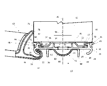
[0038] Fig. 1 is a cross-sectional, graphical illustration of a first
embodiment of a door
sweep according to the present invention, showing the door sweep mounted to a
stamped steel
rail at the bottom edge of the door panel and also showing an engagement
between an assembly
tool and a hooked finger on one end of the door sweep during installation of
the door sweep to
the rail;
[0039] Fig. 2 is an enlarged, cross-sectional, graphical illustration of
the door sweep
shown in Fig. 1, providing additional details;
[0040] Fig. 3 is a cross-sectional, graphical illustration of the
juxtaposition of the door
sweep illustrated in Fig. 2 with a sill;
[0041] Fig. 4 is a cross-sectional, graphical illustration of a second
embodiment of a door
sweep according to the present invention; and
[0042] Fig. 5 is a cross-sectional, graphical illustration of the second
embodiment of the
door sweep as illustrated in Fig. 4, showing the door sweep mounted to an
associated rail.
Detailed Description of Embodiment(s) of the Invention
[0043] The present invention will now be described in connection with one
or more
embodiments. The discussion of any one particular embodiment is not intended
to be limiting of
the present invention. To the contrary, any discussion of specific embodiments
is intended to
exemplify the breadth and scope of the present invention. As should be
apparent to those skilled
in the art, variations and equivalents of the embodiment(s) described herein
may be employed
without departing from the scope of the present invention. Those variations
and equivalents are
intended to be encompassed by the scope of the present patent application.
[0044] The content and substance of all patents and other publications
identified in the
paragraphs that follow are incorporated herein by reference in their
entireties, whether or not
explicitly stated. In addition, the content and substance of U.S. Non-
Provisional Patent
6
CA 2984306 2017-10-27
Application Serial No. 14/717,194 and U.S. Design Patent Application Serial
No. 29/527,556 are
expressly incorporated herein by reference in their entireties.
[0045] Any reference to patents and/or publications herein is provided
for the purpose of
incorporating into this patent application the subject matter described and
disclosed therein. It is
contemplated, for example, that the methodologies described in these patents
and publications
may be used in connection with the present invention. However, any subject
matter presented by
those patents and publications is not intended to provide definitions of terms
inconsistent with
those presented herein. All statements as to the date or representation as to
the contents of these
documents is based on information available to the applicants and do not
constitute any
admission as to the correctness of the dates or contents of these documents.
[0046] As used herein and in the claims, the singular forms "a," "an,"
and "the" include
the plural reference unless the context clearly indicates otherwise.
Throughout this specification,
unless otherwise indicated, "comprise," "comprises" and "comprising" are used
inclusively
rather than exclusively, so that a stated integer or group of integers may
include one or more
other non-stated integers or groups of integers. The term "or" is inclusive
unless modified, for
example, by "either." Other than in the operating examples, or where otherwise
indicated, all
numbers expressing quantities of ingredients or reaction conditions used
herein should be
understood as modified in all instances by the term "about."
[0047] Unless defined otherwise, all technical and scientific terms used
herein have the
same meaning as those commonly understood to one of ordinary skill in the art.
The terminology
used herein is for the purpose of describing particular embodiments only, and
is not intended to
limit the scope of the present invention, which is defined solely by the
claims.
[0048] The terms "male" and "female" may be used interchangeably to
describe
corresponding components or complementary aspects thereof and are not a
limitation to either
particular structure unless context clearly indicates otherwise.
[0049] Headings are provided for convenience only and are not to be
construed to limit
the invention in any way.
[0050] In order that the present disclosure can be more readily
understood, certain terms
are first defined. Additional definitions are set forth throughout the
detailed description.
7
CA 2984306 2017-10-27
[0051] A first embodiment of a door sweep 10 according to the present
invention is
provided in Fig. 1. The door sweep 10 is connected to a door 12. More
specifically, the door
sweep 10 connects to a rail 14 that is attached to a bottom surface 16 of the
door 12.
[0052] The door sweep 10 comprises a base 18. As shown, the base 18
includes a
resilient segment 20 that is disposed between a first segment 22 and a second
segment 24. The
resilient segment 20 is contemplated to assist with the installation of the
door sweep 10 onto a
door, because the resilient segment 20 permits the base 18 to flex with
respect to a centerline 26
of the base 18 when manipulated by a tool 40. Further details concerning the
installation of the
door sweep 10 to the door 12 are provided below.
[0053] As illustrated, the resilient segment 20 defines a centerline 26.
The centerline 26
is contemplated to bisect the resilient segment 20, which is symmetrical about
the centerline 26.
The centerline 26 also is contemplated to coincide with a centerline of the
door 12. It is noted,
however, that the positioning of the centerline 26 of the base with the
centerline of the door 12 is
exemplary only. The centerline 26 of the base 18 may be offset from the
centerline of the door
12 without departing from the scope of the present invention.
[0054] As points of reference, the base 18 defines an interior edge 28
and an exterior
edge 30.
[0055] The first segment 22 is defined by an exterior end 29 and an
interior end 31. Since
the second segment 24 is a mirror image of the first segment 22, the second
segment 24 also
defines the same interior end 31 and the same exterior end 29. Although it is
contemplated that
the first segment 22 will be constructed as a mirror image of the second
segment 24, the first
segment 22 may differ in its construction from the second segment 24 without
departing from the
scope of the present invention.
[0056] Since the first segment 22 and the second segment 24 are mirror
images of one
another, the discussion of features associated with the first segment 22 apply
equally to the
second segment 24.
[0057] With reference to Fig. 2, the base 18 includes a top surface 32
and a bottom
surface 34. The top surface 32 faces toward the bottom surface 16 of the door
12.
[0058] An alignment ridge 36 is attached to and extends upwardly from the
top surface
32 at a position adjacent to the exterior end 29 of the first segment 22. The
alignment ridge 36 is
8
CA 2984306 2017-10-27
provided to help align the door sweep 10 on the rail 14 attached to the bottom
surface 16 of the
door 12. The alignment ridge also provides a more stable fit between the rail
14 and the door
sweep 10.
[0059] The exterior end 29 of the first segment 22 includes a finger 38
extending
downwardly with respect to the bottom surface 34. The finger 38 is hook-shaped
and may be
engaged by the tool 40, which is shown in Fig. 1. When the tool 40 engages the
finger 38, the
tool 40 pulls on the first segment 22, the position of which is altered as
permitted by the degree
of flexibility associated with the resilient segment 20.
[0060] The top surface 32 of the first segment 22 includes a rail
engaging lip 42 and a
bulb 44 at the exterior end 29.
[0061] The rail engaging lip 42 is an L-shaped structure having a
vertical segment 46 that
extends upwardly from the top surface 32. The engaging lip 42 also includes a
horizontal
segment 48 that extends from the vertical segment 46 toward the interior end
31 and the
centerline 26. The rail engaging lip 42 includes a first rib 50 extending
downwardly toward the
top surface 32 of the first segment 22. The first segment 22 has a second rib
52 extending
upwardly from the top surface 32 of the first segment 22 toward the horizontal
segment 48. The
first rib 50 and the second rib 52 are near to one another, but offset from
one another. The
positioning of the first rib 50 and the second rib 52 in this manner
facilitates an interference fit
between the base 18 and the rail 14, specifically the offset edges 72 of the
rail 14, as shown in
Figs. 1 and 3.
[0062] The bulb 44 extends upwardly from the horizontal segment 48 of the
rail
engaging lip 42 and connects to the exterior end 29 of the first segment 22.
The bulb 44 provides
a sealing engagement between the door sweep 10 and the door 12. As
illustrated, the bulb 44
forms a compressible, tubular, hollow structure at the exterior end 29 of the
first segment 22.
[0063] As noted above, the second segment 24 shares the same construction
as the first
segment 22, except that the second segment 24 is a mirror image of the first
segment 22 due to
its positioning as a part of the base 18.
[0064] A sealing member 54 is attached to the base 18. The sealing member
54 includes
a first sealing fin 56, a second sealing fin 58, and a sealing bulb 60. The
sealing member 54 also
includes a first horizontal segment 62 and a second horizontal segment 64. The
first horizontal
9
CA 2984306 2017-10-27
segment 62 connects the first sealing fin 56 to the central bulb 60. The
second horizontal
segment 64 connects the second sealing fin 58 to the sealing bulb 60.
Collectively, the first
sealing fin 56, the second sealing fin 58, and the sealing bulb 60 establish a
seal with a sill cap 82
(shown in Fig. 3) when the door 12 is closed. The sealing member 54 helps to
discourage ingress
of water, dirt, and debris from entering the interior of the structure from
the exterior.
[0065] It is noted that the construction of the sealing member 54 is
exemplary only and is
not intended to be limiting of the present invention. It is contemplated that,
in its simplest form,
the sealing member 54 may include at least one sealing fin 56 or 58. In
another contemplated
embodiment, the sealing member 54 may include at least one sealing bulb 60.
Still further, the
sealing member 54 may include at least one fin 56 or 58 and at least one
sealing bulb 60. And, as
should be apparent to those skilled in the art, the sealing member may include
a plurality of
sealing fins 56, 58 and a plurality of sealing bulbs 60.
[0066] With continued reference to Fig. 2, the resilient segment 20, the
bulbs 44, and the
sealing member 54 are illustrated with a cross-shading. This cross-shading is
intended to convey
that these elements of the present invention are contemplated to be made from
resilient materials.
By contrast, the first segment 22 and the second segment 24 are contemplated
to be
manufactured from rigid materials, which include semi-rigid materials as
should be apparent to
those skilled in the art. Resilient materials include, but are not limited to,
flexible polyvinyl
chloride, rubber, flexible polymers, and the like. Rigid materials include,
but are not limited to,
rigid polyvinyl chloride, plastics, composites, metals, and the like.
[0067] Renewed reference is now made to Fig. 1. As indicated above, a
tool 40 may be
employed to assist with installing the door sweep 10 onto the rail 14 attached
to the bottom
surface 16 of the door 12. As should be apparent from the illustration, when
the tool 40 engages
the finger 38 on the door sweep 10, the application of leverage by a user
causes the door sweep
to flex. As noted above, the degree of flexure depends, at least in part, on
the flexibility of the
resilient segment 20.
[0068] With the assistance of the tool 40, it becomes possible to engage
a portion of the
rail engaging lip 42 onto the rail 14 for at least a portion of the door 12.
The tool 40 may then be
moved along the width of the door 12, repeating the attachment operation,
until the entire length
of the rail engaging lip 42 engages the entire length of the rail 14.
CA 2984306 2017-10-27
[0069] To install the door sweep 10 onto the rail 14, a user first mates
a first one of the
rail engaging lips 42 to the offset edge 72 of the rail 14. The first edge 74
of the tool 40 is placed
into the finger 38 on the non-engaged edge of the door sweep 10. Using the
face 76 of the door
12 as a fulcrum, the second edge 78 of the tool 40 is placed against the face
76 of the door 12.
The tool 40 is rotated towards the top edge (not shown) of the door 12. This
action causes the
central, resilient segment 20 of the door sweep 10 to extend and/or flex,
allowing the second one
of the rail engaging lips 42 to extend past the second offset edge 72 of the
rail 14. As the user
continues to rotate the tool 40, the second rail engaging lip 42 aligns with
the second offset edge
72. Upon release of the tool 40, the central, resilient segment 20 contracts,
causing the second
rail engaging lip 42 to engage the second rail edge 72 in the slot 80. This
procedure may be
repeated, as necessary, along the length of the rail 14. In this manner, the
door sweep 10 mates to
the rail 14.
[0070] The rail 14 is contemplated to be made from a rigid material. As
such, without
limiting the composition of the rail 14, the rail 14 may be made from rigid
polyvinyl chloride,
plastics, composites, metals, and the like. In the illustrated embodiment, the
rail 14 is constructed
from stamped steel.
[0071] The distance between the alignment ridges 36 also is referred to
as a mounting
slot 66. For the door sweep 10, there is only one mounting slot 66. However, a
plurality of
mounting slots 66 may be provided without departing from the scope of the
present invention.
[0072] The door sweep 10 also includes two rail engaging lips 42. While
this is
contemplated to be sufficient for the door sweep 10, it is contemplated that
the door sweep 10
might include a larger number of rail engaging lips 42 without departing from
the scope of the
present invention.
[0073] Next, the door sweep 10 includes two fingers 38. While this
construction is
contemplated to be typical, it is possible that the door sweep 10 might
include a larger number of
fingers 38 without departing for the scope of the present invention.
[0074] The first sealing fin 56, the second sealing fin 58, and the
sealing bulb 60 that are
a part of the sealing member 54 extend from the bottom of the door sweep 10.
The illustrated
configuration of the sealing member 54, however, may be altered without
departing from the
scope of the present invention. Any of a number of configurations for the
sealing member 54 are
11
CA 2984306 2017-10-27
contemplated to interact with a cap component 68 of a door sill 70 or
threshold to create a barrier
that resists infiltration of external elements, such as air, water, dirt and
debris, from the exterior
environment into the interior of the building. These configurations may embody
various size,
shape and quantities.
[0075] As should be apparent, the door sweep 10 is symmetric about the
centerline 26.
Being symmetric, the construction of the door sweep 10 allows for non-oriented
attachment. In
other words, the door sweep 10 may be installed such that the interior edge 28
and the exterior
edge 30 are reversed. However, symmetry is not required to practice the
present invention, as
noted above.
[0076] As shown in Fig. 2, and as indicated above, the rail engaging lips
42 establish
slots 80 that receive the offset edges 72 of the rail 14. The first rib 50 and
the second rib 52 help
to hold the door sweep 10 on the rail 14 by engaging each offset edge 72. The
first rib 50 and the
second rib 52 are contemplated to be made from a flexible material. While not
limiting the
present invention, the flexible material may be flexible polyvinyl chloride,
rubber, flexible
polymers, and the like. The first and second ribs 50, 52 engage and mate with
the offset edges 72
of the rail 14 to prevent migration of air or water from the exterior to the
interior of a building
when the door 12 is closed.
[0077] The flexible bulbs 44 also are contemplated to be co-extruded onto
the top surface
of the door sweep 10 to act as a primary seal between the door sweep 10 and
the door 12. The
ribs 50, 52 also are contemplated to be co-extruded with the first segment 22
and the second
segment 24.
[0078] The alignment ridges 36 project upwardly from the base 18 and
extend toward the
rail 14. As noted above, the alignment ridges 36 act as spacers to keep the
base 18 relatively
parallel to the bottom surface 16 of the door 12.
[0079] The sealing member 54 is contemplated to be co-extruded with the
base 18. The
sealing member 54 mates with the door sill 70, sill cap 82, or another
associated, threshold cap
component to ensure a weather seal at this intersection.
[0080] The door sweep 10 is contemplated to be an extrusion where both
the flexible and
rigid materials are co-extruded. For this reason, it is contemplated that
flexible polyvinyl
chloride and rigid polyvinyl chloride will be used for flexible and rigid
elements of the door
12
CA 2984306 2017-10-27
sweep 10. As noted, however, other materials may be employed without departing
from the
scope of the present invention.
[0081] Fig. 3 provides a graphical side view of the door sweep 10 as it
might appear
when engaging a door sill 70 to establish a seal between the door 12 and the
door sill 70 when
the door 12 is closed. The door sill 70 is contemplated to be mounted on a
floor of the house,
building or structure in which the door sweep 10 is employed. When the door 12
is closed, the
resilient member 54 of the door sweep 10 engages a sill cap 82 of the sill 70.
This ensures a
weather seal between the floor and the door sweep 10.
[0082] Fig. 4 is a graphical, cross-sectional side view of a second
embodiment of a door
sweep 84 according to the present invention. Despite differences in its
appearance and
construction, the door sweep 84 shares many of the same features as the door
sweep 10.
[0083] The door sweep 84 includes a base 86 that combines a resilient
segment 88, a first
segment 90, and a second segment 92. As with the door sweep 10, the resilient
segment 88 is
made from a resilient material and connects the first segment 90 to the second
segment 92. The
first and second segments 90, 92 are contemplated to be made from rigid or
semi-rigid materials,
the details of which are provided in connection with the discussion of the
door sweep 10. The
resilient segment 88 permits the door sweep 84 to flex with respect to a
centerline 94 when the
door sweep 84 is manipulated by the tool 40 in the manner described above.
[0084] As in the prior embodiment, the centerline 94 bisects the door
sweep 84, which is
symmetrical about the centerline 94. Similarly, the first segment 90 and the
second segment 92
are mirror images of one another. As such, the first and second segments 90,
92 define exterior
ends 96 and interior ends 98. As before, the door sweep 84 defines an interior
edge 102 and an
exterior edge 100. Although it is contemplated that the first segment 90 will
be constructed as a
mirror image of the second segment 92, the first segment 90 may differ in its
construction from
the second segment 92 without departing from the scope of the present
invention.
[0085] Since the first segment 90 and the second segment 92 are mirror
images of one
another, the discussion of features associated with the first segment 90 apply
equally to the
second segment 92.
[0086] With reference to Fig. 4, the base 86 includes a top surface 104
and a bottom
surface 106. The top surface 104 faces toward the bottom surface 16 of the
door 12. An
13
CA 2984306 2017-10-27
alignment ridge 108 is attached to and extends upwardly from the top surface
104 at a position
adjacent to the exterior end 96 of the first segment 90. The alignment ridge
108 is provided to
help align the door sweep 84 on the rail 14 attached to the bottom surface 16
of the door 12. The
alignment ridge 108 provides a more stable fit between the rail 14 and the
door sweep 84.
[0087] The exterior end 96 of the first segment 90 includes a finger 110
extending
downwardly with respect to the bottom surface 106. The finger 110 is hook-
shaped and is
provided to engage the tool 40, which is shown in Fig. 1. When the tool 40
engages the finger
110, the tool 40 pulls on the first segment 90, the position of which is
altered as permitted by the
degree of flexibility associated with the resilient segment 88.
[0088] The top surface 104 of the first segment 90 defines a rail
engaging lip 112 and a
pincer 114 at the exterior end 96.
[0089] The rail engaging lip 112 is disposed apart from the top surface
104 due to the
shape of the first segment 90. The rail engaging lip 112 establishes a slot
116 that accommodates
an offset edge 72 of the rail 14.
[0090] The pincer 114 includes a first pincer element 118 and a second
pincer element
120. The first pincer element 118 is longer than the second pincer element
120. The first pincer
element 118 also is disposed at a position closer to the centerline 94 than
the second pincer
element 120. When installed on the door 12, the first pincer element 118 is
squeezed into
engagement with the second pincer element 120, thereby establishing a suitable
seal between the
door sweep 84 and the door 12.
[0091] As noted above, the second segment 92 shares the same construction
as the first
segment 90, except that the second segment 92 is a mirror image of the first
segment 90 due to
its positioning as a part of the base 86.
[0092] A sealing member 122 is attached to the base 86. The sealing
member 122
includes a first sealing fin 124, a second sealing fin 126, and a sealing bulb
128. Collectively, the
first sealing fin 124, the second sealing fin 126, and the sealing bulb 128
establish a seal with a
sill cap 82, such as the one shown in Fig. 3, when the door 12 is closed. The
sealing member 122
helps to discourage ingress of water, dirt, and debris from entering the
interior of the structure
from the exterior.
14
CA 2984306 2017-10-27
[0093] As with the sealing member 54, however, the construction of the
sealing member
122 is intended to be a non-limiting example. The sealing member 122 may
include at least one
sealing fin 124 or 126. In another contemplated embodiment, the sealing member
122 may
include at least one sealing bulb 128. Still further, the sealing member 122
may include at least
one fin 124 or 126 and at least one sealing bulb 128. And, as should be
apparent to those skilled
in the art, the sealing member may include a plurality of sealing fins 124,
126 and a plurality of
sealing bulbs 128.
[0094] With reference to Figs. 4 and 5, the resilient segment 88, the
pincers 114, and the
sealing member 122 are illustrated with a cross-shading. This cross-shading is
intended to
convey that these elements of the present invention are contemplated to be
made from resilient
materials. By contrast, the first segment 90 and the second segment 92 are
contemplated to be
manufactured from rigid materials, which include semi-rigid materials as
should be apparent to
those skilled in the art. Resilient materials include, but are not limited to,
flexible polyvinyl
chloride, rubber, flexible polymers, and the like. Rigid materials include,
but are not limited to,
rigid polyvinyl chloride, plastics, composites, metals, and the like.
[0095] The door sweep 84 is contemplated to be installed on the rail 14
in the same
manner as described in connection with the door sweep 10. The tool 40 is
contemplated to be
used in the manner discussed above.
[0096] In particular, the method includes: (a) positioning a second edge
72 of the rail 14
into the second slot 116, (b) engaging a first edge 74 of a mounting tool 40
into the first finger
110, (c) engaging a second edge 78 of the mounting tool 40 onto a face of the
door 12, (d)
rotating the mounting tool 40 towards a top edge of the door 12, (e) extending
the first rail
engaging lip 112 away from the second slot 116, thereby aligning at least a
portion of the first
slot 116 with the first edge 72 of the rail 12, and (f) disengaging the
mounting tool 40 from the
first finger 110 while maintaining the at least a portion of the first slot
116 with the first edge 72
of the rail 14. Steps (a) ¨ (f) may be repeated in sequence along a length of
the first finger 110
until the door sweep 84 completely engages the rail 14. Alternatively, the
method may include
repeating steps (b) ¨ (f) in sequence along a length of the first finger 110
until the door sweep 84
completely engages the rail 14.
CA 2984306 2017-10-27
[0097] It should be understood that the examples and embodiments
described herein are
for illustrative purposes only and that various modifications or changes in
light thereof will be
suggested to persons skilled in the art and are to be included within the
spirit and purview of this
application and the scope of the appended claims. All publications and patent
applications
mentioned in this specification are indicative of the level of skill of those
skilled in the art to
which this invention pertains. All publications and patent applications are
herein incorporated by
reference to the same extent as if each individual publication or patent
application was
specifically and individually indicated to be incorporated by reference.
[0098] As noted above, the embodiment(s) described herein are intended to
be exemplary
of the wide breadth of the present invention. Variations and equivalents of
the described
embodiment(s) are intended to be encompassed by the present invention, as if
described herein.
16
CA 2984306 2017-10-27