Sélection de la langue

Search

Sommaire du brevet 2985664 

Énoncé de désistement de responsabilité concernant l'information provenant de tiers

Une partie des informations de ce site Web a été fournie par des sources externes. Le gouvernement du Canada n'assume aucune responsabilité concernant la précision, l'actualité ou la fiabilité des informations fournies par les sources externes. Les utilisateurs qui désirent employer cette information devraient consulter directement la source des informations. Le contenu fourni par les sources externes n'est pas assujetti aux exigences sur les langues officielles, la protection des renseignements personnels et l'accessibilité.

Disponibilité de l'Abrégé et des Revendications

L'apparition de différences dans le texte et l'image des Revendications et de l'Abrégé dépend du moment auquel le document est publié. Les textes des Revendications et de l'Abrégé sont affichés :

  • lorsque la demande peut être examinée par le public;
  • lorsque le brevet est émis (délivrance).
(12) Brevet: (11) CA 2985664
(54) Titre français: AIDE AU POSITIONNEMENT POUR INTERVENTIONS CHIRURGICALES
(54) Titre anglais: POSITIONING AID FOR SURGICAL PROCEDURES
Statut: Accordé et délivré
Données bibliographiques
(51) Classification internationale des brevets (CIB):
  • A61B 90/11 (2016.01)
  • A61B 17/17 (2006.01)
(72) Inventeurs :
  • ORTMAIER, TOBIAS (Allemagne)
  • MAJDANI, OMID (Allemagne)
  • RAU, THOMAS STEPHAN (Allemagne)
  • LENARZ, THOMAS (Allemagne)
  • KOBLER, JAN-PHILIPP (Allemagne)
  • KLUGE, MARCEL (Allemagne)
  • JOHN, SAMUEL (Allemagne)
(73) Titulaires :
  • OTOJIG GMBH
(71) Demandeurs :
  • OTOJIG GMBH (Allemagne)
(74) Agent: SMART & BIGGAR LP
(74) Co-agent:
(45) Délivré: 2022-07-19
(86) Date de dépôt PCT: 2015-06-08
(87) Mise à la disponibilité du public: 2016-12-15
Requête d'examen: 2020-05-05
Licence disponible: S.O.
Cédé au domaine public: S.O.
(25) Langue des documents déposés: Anglais

Traité de coopération en matière de brevets (PCT): Oui
(86) Numéro de la demande PCT: PCT/DE2015/100227
(87) Numéro de publication internationale PCT: DE2015100227
(85) Entrée nationale: 2017-11-10

(30) Données de priorité de la demande: S.O.

Abrégés

Abrégé français

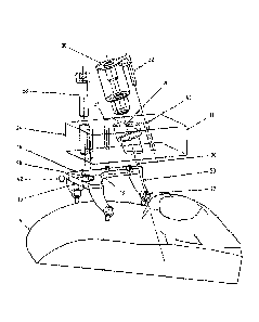
L'invention concerne une aide au positionnement pour interventions chirurgicales comprenant un système de support (10) et un gabarit (12), ledit système de support (10) étant constitué d'une plaque de support (16) dotée d'un renfoncement (18) et de montants (20). La plaque de support (16) peut être fixée sur un os du crâne (14) au moyen des montants (20) au-dessus d'un champ opératoire pour l'intervention chirurgicale. Le gabarit (12) comprend une plaque de gabarit (24) dotée d'une ouverture de guidage (26) et pouvant être reliée sans jeu avec la plaque de support (16). Dans la plaque de gabarit (24) constituée d'une préforme, l'ouverture de guidage (26) est aménagée et orientée individuellement d'après des coordonnées prédéterminées. L'axe médian longitudinal de l'ouverture de guidage (26) correspond, quand le système de support (10), le gabarit (12) et le système de support (10) fixé sur l'os du crâne (14) sont rassemblés, à une trajectoire pour un accès au champ opératoire pour l'intervention chirurgicale.


Abrégé anglais

The invention relates to a positioning aid for surgical procedures, comprising a support system (10) and a guide (12). The support system (10) consist of a support plate (16), which is provided with a recess (18), and supports (20). The support plate (16) can be secured to a cranial bone (14) via the supports (20) over an operating field for the surgical procedure. The guide (12) comprises a guide plate (24) which can be connected to the support plate (16) in a play-free manner and which comprises a guide opening (26). The guide opening (26) is arranged and oriented in the guide plate (24), which consists of a blank, in an individualized manner according to coordinates ascertained in advance. The central longitudinal axis of the guide opening (26) matches a trajectory for accessing the operating field for the surgical procedure when the support system (10) and the guide (12) are assembled and the support system (10) is secured to the cranial bone (14).

Revendications

Note : Les revendications sont présentées dans la langue officielle dans laquelle elles ont été soumises.


16
Claims
1. A positioning aid for surgical interventions, comprising a carrier
system (10) and a
template (12), wherein the carrier system (10) consists of a carrier plate
(16)
provided with a recess (18), and of supports (20), by means of which the
carrier
plate (16), over an operating field for surgical intervention, is securable to
a cranial
bone (14), and the template (12) consists of a template plate (24) which is
securable
in a play-free manner to the carrier plate (16), said template plate (24)
having a
guiding aperture (26), wherein the template plate (24) consists of a blank
in which the guiding aperture (26) is arranged and oriented individually in
accordance with predetermined coordinates by means of removal of material of
the
blank,
and a longitudinal central axis (36) of the guiding aperture (26), when the
carrier
system (10) and template (12) are in the assembled state and the carrier
system
(10) is fixed to the cranial bone (14), corresponds to a trajectory for an
access to the
operating field for the surgical intervention, characterised in that the
longitudinal
central axis (36) of the guiding aperture (26) is arranged eccentrically
relative to the
template plate (24), has an incline of the longitudinal central axis (36)
thereof which
deviates from the vertical of the surface of the template plate (24), and the
recess in
the carrier plate (16) is dimensioned to be of such a size that the guiding
aperture
(26) in the template plate (24) is not covered by the carrier plate (16) even
in the
case of maximum eccentric arrangement.
2. The positioning aid according to Claim 1, characterised in that the
supports (20),
at the ends thereof facing away from the carrier plate, either
a) have a hole pattern, wherein the holes are penetration and fixing
locations of
bone anchors or
b) comprise a plurality of bone anchors or
c) bear mandrel-type pins for bracing against the cranial bone by means
of bone screws.
3. The positioning aid according to Claim 1 or 2, characterised in that the
supports
comprise predetermined breaking points.
4. The positioning aid according to any one of Claims 1 to 3, characterised
in that
a) pins (28) are arranged on one of the two plates, namely the
carrier plate (16)
or the template plate (24), and recesses (34) for receiving the pins (28) are
arranged on the respective other plate, namely the template plate (24) or the

17
carrier plate (16), and in the mounted state the pins (28) of one plate fit
into
the recesses (34) of the other plate, or
b) on both plates, namely both the carrier plate (16) and the template
plate (24),
there are recesses present for receiving pins, and in the mounting state pins
respectively fit into both recesses of the plates and
in that the plates are tightened against one another.
5. The positioning aid according to Claim 4, characterised in that at least
two pins
(28) or recesses (34) are respectively present and are designed differently
and/or
are arranged asymmetrically.
6. The positioning aid according to any one of Claims 1 to 5, characterised
in that an
exchangeable cylindrical tool-guiding body (30) is arranged in the guiding
aperture
(26).
7. The positioning aid according to Claim 6, characterised in that the tool-
guiding body
(30) has a stopper for the depth adjustment of a tool.
8. The positioning aid according to Claim 6 or 7, characterised in that the
tool-
guiding body (30) has an anti-rotation device which engages in a recess (40)
arranged beside the guiding aperture (26) in the template plate (24).
9. The positioning aid according to any one of Claims 1 to 8, characterised
in that the
recess (18) in the carrier plate (16) and the guiding aperture (26) in the
template
plate (24) have an outwardly leading slot or a U-shaped open form.
10. The positioning aid according to any one of Claims 1 to 9,
characterised in that
registering markings (42) are arranged on the carrier system (10) or the
carrier
system itself or parts thereof are designed as registering markings.

Description

Note : Les descriptions sont présentées dans la langue officielle dans laquelle elles ont été soumises.


- 1 -
Positioning aid for surgical procedures
The invention relates to a positioning aid for surgical
procedures.
In surgical procedures on the cranium, as they are required for
implantation of a cochlear implant, for example, until now the
conventional method of procedure provided for uncovering of all
relevant risk structures of the lateral cranium base, in order
to guarantee its intactness. Subsequently, the middle ear is
opened up between the facial nerve and the gustatory nerve, in
order to thereby establish access to the inner ear.
To reduce the time expenditure, the operative risk, and the
trauma, a minimally invasive approach is pursued. On the basis
of pre-operative image data and planning data of the individual
anatomy, access in the form of an individual puncture channel
bore is placed from the cranium surface to the cochlea. In this
regard, uncovering of the risk structures is not performed, nor
is continuous tracking of patient and instruments. However,
this requires highly precise implementation of planning data.
Date Recue/Date Received 2021-09-24

CA 02985664 2017-11-10
WO 2016/198032 PCT/DE2015/100227
From US 7,981,122 B2, a positioning aid is already known that is
referred to as a micro-table among experts. The known
positioning aid consists of a plate having a central bore that
runs perpendicular to the surface of the plate, and legs that
are affixed in pockets of the plate milled for the surgical
procedure in accordance with planning data. The legs are kept on
hand in graduated lengths, and it determined by means of the
depth of the pockets how far the legs project out of the plate.
The plate can be spatially positioned and oriented on the
cranial bone by way of the selected length of the legs and the
depths of the pockets. It is simultaneously attached by way of
ball markers anchored in the bone, which are disposed at ends of
the legs that are at a distance from the plate.
Attachment of the legs in the pockets of the plate requires
individual post-machining of the blanks. The ball markers that
are anchored in the bone have a dual function. They function as
registration markers and serve for anchoring the drilling
template on the cranium. The design of the bone-anchored ball
markers is therefore a compromise between the two requirements
and leads to restricted precision.

- 3 -
Since the predetermined axis of the bore in the plate must be
made to match the trajectory for the access to the cochlea,
installation and adjustment of the positioning aid on the
cranial bone is very time-consuming and tool-intensive. Also,
sterile production is not guaranteed, so that additional
sterilization must be carried out. In addition, this design
offers only restricted mechanical strength.
The invention is based on the task of improving a positioning
aid to the effect that it can withstand stress, and can be
installed and removed precisely and quickly.
This task is accomplished, in the case of a positioning aid
as described, by means of the device described below.
Further developments and advantageous embodiments are evident
from the following.
The positioning aid according to the invention is structured in
two parts and consists of a support system and a template. The
support system can be reused and can be kept on hand in multiple
sizes for different cranium sizes and shapes. The support
Date Recue/Date Received 2021-09-24

CA 02985664 2017-11-10
W02016/198032 PCT/DE2015/100227
- 4 -
system comprises a support plate having a recess. Here, a
recess is understood to be a cavity that leads from one flat
side of the support plate to the other and is enclosed, in whole
or in part. A fully enclosed cavity preferably has a circular
shape in a top view, while a partially enclosed cavity
represents an indentation that can have a U-shaped, half-moon-
shaped, sickle-shaped design, for example.
The template, in contrast, is specially produced for every
procedure, from a blank that matches the selected support
system. This can be a uniform body that consists of material
that is present throughout, at first in the region of possible
guide openings, into which body the guide openings are
individually introduced in accordance with predetermined
coordinates, by means of material removal such as boring,
milling, for example. On the basis of previously created
planning data for the surgical procedure, coordinates of a
trajectory for access to the operating field for the surgical
procedurn are calculated. By means of transformation of these
coordinates onto the template, the location and the orientation
for the guide opening in the template plate are established, and
the guide openings are carried out as drilled or milled holes.
The template plate with the guide opening is a component that

CA 02985664 2017-11-10
WO 2016/198032 PCTME2015/100227
- 5 -
ca n be used only once, since the location and orientation of the
guide opening relate to the individual anatomy of a patient and
to the attachment location of the support system on the cranial
bone.
Thus, first the support system can be positioned freely on the
cranial bone, within limits, without having to pay attention to
the trajectory for creating the access to the operating field.
As a result, the support plate of the snpport system can be
affixed closely to the cranial bone. In this regard, it is
preferably oriented parallel to a tangential plane of the
cranial bone, the contact point of which lies approximately in
the center of the support plate. The resulting distances of the
edges of the support plate from the cranial bone likewise allow
short supports, and this has an advantageous effect on their
mechanical stability. This is because deflection of the
supports is less under the effect of force, and thereby greater
precision of the orientation of the surgical tools is
guaranteed.
Since the support system is prefabricated, it can be kept on
hand in the sterile state. In the case of the template, only
the guide opening has to be introduced into the template plate,

CA 02985664 2017-11-10
WO 2016/198032 PCT/DE2015/100227
- 6 -
and this can take place under sterile conditions. The time
between the start of installation of the positioning aid until
the start of the surgical procedure can be clearly reduced as
compared with other systems.
Multiple variants are provided for the ends of the supports that
face away from the support plate. The ends can either
a) have a hole raster, wherein the holes are passage sites and
attachment sites of bone anchors, or
b) comprise a plurality of bone anchors, or
c) carry mandrel-like pins that can be braced relative to the
cranial bone by means of bone screws.
By means of these possible methods of attachment, the support
system can be anchored on the cranial bone in such stable manner
that the required dimensional accuracy for use of the surgical
tools is guaranteed, and the forces that occur during the
procedure can also be absorbed without changing the position of
the positioning aid.
It can be provided that the supports comprise planned breaking
points.

CA 02985664 2017-11-10
VA) 2016/198032 PCT/DE2015/100227
- 7 -
As a result, it is possible to quickly remove the support system
even without loosening the anchors in the cranial bone.
Alternative means can be provided for precise orientation of the
template plate on the support plate. Thus, the possibility
exists that
a) pins are disposed on one of the two plates, namely the
support plate or the template plate, and recesses for
accommodation of the pins are disposed on the other plate, in
each instance, namely the template plate or the support plate,
and the pins of the one plate are inserted into the recesses of
the other plate in the installed state, or
c) recess for accommodation of pins are present on both plates,
namely both on the support plate and on the template plate, and
in the installed state, pins are inserted into both recesses of
the plate, in each instance, and that the plates are braced
against one another.
This can be implemented in known manner, by means of screws,
springs or clamps.
Both variants allow a play-free connection between the template
plate and the support plate.

CA 02985664 2017-11-10
WO 2016/198032 = PCT/DE2015/100227
-B-
The pins or recesses can be present at least in duplicate, in
each instance, and can be structured differently and/or disposed
asymmetrically.
In the case of skillful distribution over the support system,
two pins or recesses are already unique. If they are
additionally also structured differently, for example have
different diameters or cross-sectional shapes, they only fit
together in one possible orientation. Alternatively, three
asymmetrically disposed pins or recesses are suitable.
In this way, the result is achieved that the template plate can
be connected with the support plate only in a single possible
orientation. Incorrect orientations are thereby reliably
prevented.
Preferably, a replaceable cylindrical tool guide body is
disposed in the guide opening.
The tool guide body can be dimensioned and removed in a manner
specifically for use of surgical tools, in such a manner that
room is guaranteed for introduction of an implant.

CA 02985664 2017-11-10
WO 2016/198032 IPCT/DE2015/100227
- 9 -
Preferably, the tool guide body has a stop for depth adjustment
of a tool.
In this way, the penetration depth of a surgical tool can
automatically be restricted.
Furthermore, the tool guide body can have an anti-twist device
in the form of a pin that engages into a recess disposed next to
the guide opening in the template plate.
In this way, the tool guide body is prevented from being twisted
when a torque is exerted.
The recess in the support plate and the guide opening in the
template plate can have a slit that is open toward the outside
or a U-shaped open shape.
In this way, it is possible to supply cables to the positioning
aid from the side when inserting an implant.

CA 02985664 2017-11-10
WO 2016/198032 PCT/DE2015/100227
- 10 -
Furthermore, registration markings can be disposed on the
support system, or the support system itself or parts of it can
themselves be structured as registration markings.
The registration markings allow spatial detection of the support
system affixed to the cranial bone relative to the anatomy of
the cranium of the patient within the scope of three-dimensional
imaging. Precise spatial detection of the support system
affixed to the cranial bone in turn is a prerequisite for
transfer of the coordinates of the guide opening in the template
plate, so that its axis matches the trajectory for access to the
operating field after installation of the template plate on the
support plate.
In the following, the invention will be explained using an
exemplary embodiment, which is represented in the drawing. This
shows:
Fig. 1 a perspective view of a positioning aid in an exploded
representation, and
Fig. 2 a perspective view of the positioning aid in the
installed state.

CA 02985664 2017-11-10
WO 2016/198032 PCT/DE2015/100227
- 11 -
The positioning aid for surgical procedures shown in Figures 1
and 2 comprises a support system 10 and a template 12. The
support system 10 consists of a support plate 16 provided with a
recess 18, and supports 20, by means of which the support plate
16 is attached to a cranial bone 14 above an operating field for
the surgical procedure. The template 12 consists of a template
plate 24 having a guide opening, which plate can be connected
with the support plate 16 in play-free and shape-fit manner.
The longitudinal center axis 36 of this guide opening 26 can be
disposed and oriented individually, according to predetermined
coordinates, on an access to the operating field for the
surgical procedure. It can therefore, as shown in the exemplary
embodiment, be disposed eccentrically relative to the template
plate 24, and have an inclination of its longitudinal center
axis 36 that deviates from the perpendicular to the surface of
the template plate 24.
The recess 18 in the support plate 16 is dimensioned to be so
large that the guide opening 26 in the template plate 24 is not
covered by the support plate 16 even in the case of maximally
eccentric placement. There are supports 20 at three locations
of the flat side of the support plate 16 that faces the cranial

CA 02985664 2017-11-10
WO 2016/198032 PCT/DE2015/100227
- 12 -
bone 14, with which supports the support plate 16 is supported
on the cranial bone 14 and can be fixed in place. At the ends,
there are feet 22 having mandrel-like pins. The feet 22 support
themselves on the skin or the cranial bone 14. The support
plate 16 is braced against the cranial bone by means of a bone
screw.
Close to the edges of the support plate 16, there are pins 26
that project toward the template plates 24 and align with
recesses 34 of the template plate 24. The pins 28 and recesses
34 are disposed asymmetrically and permit the template plate 24
and support plate 16 to be put together only in a single one of
three angle positions that appear possible at first. Here, the
template plate 24 is fixed in place with the support plate 16 by
means of three screws 38, which are screwed onto threads of the
pins 28. The template plate 24 and the support plate 16 are
oriented without play relative to one another by means of the
pins 28 and recesses 34.
Above the guide opening 26 in the template plate 24, there is a
tool guide body 30 that serves for guiding and holding a
surgical tool. An anti-twist device in the form of a pin 32 is
disposed on the tool guide body 30, which pin engages into a

CA 02985664 2017-11-10
W02016/198032 PCT/DE2015/100227
- 13 -
recess 40 of the template plate 24 when the tool guide body 30
is inserted into the guide opening 26.
While the positioning pins are shown in an exploded
representation in Fig. 1, the individual components are shown in
the installed state in Fig. 2.
In the preparation for a surgical procedure, first the anatomy
of the cranium of a patient is recorded by means of imaging
methods, and thereupon the surgical procedure is planned. A
component of this planning is orientation of a common axis for a
drilled or milled hole in the cranial bone and further access to
the operating field. A support system 10 is selected on the
basis of the size and shape of the cranium, which system is
fixed in place on the cranial bone 14. The registration
markings 42 affixed on the support system 10, which markings
have the greatest possible distance from one another, serve for
determining the spatial placement of the support system 10
attached to the cranial bone 14 relative to the anatomy of the
cranium of the patient. These registration markings 42 are
represented more clearly than the other components of the
support system 10 within the scope of a subsequent three-
dimensional imaging of the patient, and thereby facilitate

CA 02985664 2017-11-10
W02016/198032 PCT/DE2015/100227
- 14 -
detection of the coordinates of the support system 10. The
coordinates of the support system 10 as well as of the
trajectory for access to the operating field are transferred to
the template plate 24. The location and the inclination for the
guide opening 36 in the template plate 24 are determined from
this, and this opening is produced. Afterward, the template
plate 24 is fixed in place on the support plate 16 and the tool
guide body 30 is inserted.
With this, the mechanical prerequisites for precise guidance of
the surgical tool for opening up the cranial bone, advancing to
the operating field, and inserting the implant have been
completed.

CA 02985664 2017-11-10
WO 2016/198032 PCT/DE2015/100227
- 15 -
Reference Symbol List
support system
12 template
14 cranial bone
16 support plate
18 recess
supports
22 feet
24 template plate
26 guide opening
28 pins
tool guide body,
32 pin
34 recesses
36 longitudinal center axis
38 screws
recess
42 registration markings

Dessin représentatif
Une figure unique qui représente un dessin illustrant l'invention.
États administratifs

2024-08-01 : Dans le cadre de la transition vers les Brevets de nouvelle génération (BNG), la base de données sur les brevets canadiens (BDBC) contient désormais un Historique d'événement plus détaillé, qui reproduit le Journal des événements de notre nouvelle solution interne.

Veuillez noter que les événements débutant par « Inactive : » se réfèrent à des événements qui ne sont plus utilisés dans notre nouvelle solution interne.

Pour une meilleure compréhension de l'état de la demande ou brevet qui figure sur cette page, la rubrique Mise en garde , et les descriptions de Brevet , Historique d'événement , Taxes périodiques et Historique des paiements devraient être consultées.

Historique d'événement

Description Date
Inactive : Octroit téléchargé 2022-07-22
Accordé par délivrance 2022-07-19
Lettre envoyée 2022-07-19
Inactive : Page couverture publiée 2022-07-18
Préoctroi 2022-05-05
Inactive : Taxe finale reçue 2022-05-05
Un avis d'acceptation est envoyé 2022-02-16
Lettre envoyée 2022-02-16
month 2022-02-16
Un avis d'acceptation est envoyé 2022-02-16
Inactive : Approuvée aux fins d'acceptation (AFA) 2022-01-05
Inactive : QS réussi 2022-01-05
Modification reçue - modification volontaire 2021-09-24
Modification reçue - réponse à une demande de l'examinateur 2021-09-24
Requête pour le changement d'adresse ou de mode de correspondance reçue 2021-09-24
Rapport d'examen 2021-06-08
Inactive : Rapport - Aucun CQ 2021-05-25
Représentant commun nommé 2020-11-07
Lettre envoyée 2020-06-01
Inactive : COVID 19 - Délai prolongé 2020-05-28
Exigences pour une requête d'examen - jugée conforme 2020-05-05
Requête d'examen reçue 2020-05-05
Requête pour le changement d'adresse ou de mode de correspondance reçue 2020-05-05
Toutes les exigences pour l'examen - jugée conforme 2020-05-05
Représentant commun nommé 2019-10-30
Lettre envoyée 2018-11-14
Inactive : Transfert individuel 2018-11-08
Requête pour le changement d'adresse ou de mode de correspondance reçue 2018-01-12
Inactive : Page couverture publiée 2017-11-29
Inactive : CIB en 1re position 2017-11-28
Inactive : CIB enlevée 2017-11-28
Inactive : Notice - Entrée phase nat. - Pas de RE 2017-11-27
Inactive : CIB attribuée 2017-11-21
Demande reçue - PCT 2017-11-21
Exigences pour l'entrée dans la phase nationale - jugée conforme 2017-11-10
Modification reçue - modification volontaire 2017-11-10
Demande publiée (accessible au public) 2016-12-15

Historique d'abandonnement

Il n'y a pas d'historique d'abandonnement

Taxes périodiques

Le dernier paiement a été reçu le 2022-05-30

Avis : Si le paiement en totalité n'a pas été reçu au plus tard à la date indiquée, une taxe supplémentaire peut être imposée, soit une des taxes suivantes :

  • taxe de rétablissement ;
  • taxe pour paiement en souffrance ; ou
  • taxe additionnelle pour le renversement d'une péremption réputée.

Les taxes sur les brevets sont ajustées au 1er janvier de chaque année. Les montants ci-dessus sont les montants actuels s'ils sont reçus au plus tard le 31 décembre de l'année en cours.
Veuillez vous référer à la page web des taxes sur les brevets de l'OPIC pour voir tous les montants actuels des taxes.

Historique des taxes

Type de taxes Anniversaire Échéance Date payée
Taxe nationale de base - générale 2017-11-10
TM (demande, 2e anniv.) - générale 02 2017-06-08 2017-11-10
TM (demande, 3e anniv.) - générale 03 2018-06-08 2018-05-01
Enregistrement d'un document 2018-11-08
TM (demande, 4e anniv.) - générale 04 2019-06-10 2019-05-03
TM (demande, 5e anniv.) - générale 05 2020-06-08 2020-04-07
Requête d'examen - générale 2020-06-15 2020-05-05
TM (demande, 6e anniv.) - générale 06 2021-06-08 2021-06-01
Taxe finale - générale 2022-06-16 2022-05-05
TM (demande, 7e anniv.) - générale 07 2022-06-08 2022-05-30
TM (brevet, 8e anniv.) - générale 2023-06-08 2023-05-23
TM (brevet, 9e anniv.) - générale 2024-06-10 2024-05-27
Titulaires au dossier

Les titulaires actuels et antérieures au dossier sont affichés en ordre alphabétique.

Titulaires actuels au dossier
OTOJIG GMBH
Titulaires antérieures au dossier
JAN-PHILIPP KOBLER
MARCEL KLUGE
OMID MAJDANI
SAMUEL JOHN
THOMAS LENARZ
THOMAS STEPHAN RAU
TOBIAS ORTMAIER
Les propriétaires antérieurs qui ne figurent pas dans la liste des « Propriétaires au dossier » apparaîtront dans d'autres documents au dossier.
Documents

Pour visionner les fichiers sélectionnés, entrer le code reCAPTCHA :


Pour visualiser une image, cliquer sur un lien dans la colonne description du document (Temporairement non-disponible). Pour télécharger l'image (les images), cliquer l'une ou plusieurs cases à cocher dans la première colonne et ensuite cliquer sur le bouton "Télécharger sélection en format PDF (archive Zip)" ou le bouton "Télécharger sélection (en un fichier PDF fusionné)".

Liste des documents de brevet publiés et non publiés sur la BDBC .

Si vous avez des difficultés à accéder au contenu, veuillez communiquer avec le Centre de services à la clientèle au 1-866-997-1936, ou envoyer un courriel au Centre de service à la clientèle de l'OPIC.

({010=Tous les documents, 020=Au moment du dépôt, 030=Au moment de la mise à la disponibilité du public, 040=À la délivrance, 050=Examen, 060=Correspondance reçue, 070=Divers, 080=Correspondance envoyée, 090=Paiement})


Description du
Document 
Date
(aaaa-mm-jj) 
Nombre de pages   Taille de l'image (Ko) 
Description 2017-11-09 17 357
Dessins 2017-11-09 3 53
Revendications 2017-11-09 4 77
Abrégé 2017-11-09 2 105
Dessin représentatif 2017-11-09 1 21
Revendications 2017-11-10 2 71
Revendications 2021-09-23 2 86
Description 2021-09-23 15 344
Dessins 2021-09-23 2 49
Dessin représentatif 2022-06-27 1 13
Paiement de taxe périodique 2024-05-26 8 294
Courtoisie - Certificat d'enregistrement (document(s) connexe(s)) 2018-11-13 1 107
Avis d'entree dans la phase nationale 2017-11-26 1 193
Courtoisie - Réception de la requête d'examen 2020-05-31 1 433
Avis du commissaire - Demande jugée acceptable 2022-02-15 1 570
Traité de coopération en matière de brevets (PCT) 2017-11-09 8 291
Rapport de recherche internationale 2017-11-09 3 89
Modification volontaire 2017-11-09 4 123
Demande d'entrée en phase nationale 2017-11-09 7 176
Déclaration 2017-11-09 3 111
Requête d'examen 2020-05-04 4 124
Changement à la méthode de correspondance 2020-05-04 4 124
Demande de l'examinateur 2021-06-07 3 168
Modification / réponse à un rapport 2021-09-23 17 493
Changement à la méthode de correspondance 2021-09-23 3 75
Taxe finale 2022-05-04 4 119
Certificat électronique d'octroi 2022-07-18 1 2 527