Sélection de la langue

Search

Sommaire du brevet 2986500 

Énoncé de désistement de responsabilité concernant l'information provenant de tiers

Une partie des informations de ce site Web a été fournie par des sources externes. Le gouvernement du Canada n'assume aucune responsabilité concernant la précision, l'actualité ou la fiabilité des informations fournies par les sources externes. Les utilisateurs qui désirent employer cette information devraient consulter directement la source des informations. Le contenu fourni par les sources externes n'est pas assujetti aux exigences sur les langues officielles, la protection des renseignements personnels et l'accessibilité.

Disponibilité de l'Abrégé et des Revendications

L'apparition de différences dans le texte et l'image des Revendications et de l'Abrégé dépend du moment auquel le document est publié. Les textes des Revendications et de l'Abrégé sont affichés :

  • lorsque la demande peut être examinée par le public;
  • lorsque le brevet est émis (délivrance).
(12) Brevet: (11) CA 2986500
(54) Titre français: PROCEDE POUR AUGMENTER LA CAPACITE D'UNE USINE D'AMMONIAC
(54) Titre anglais: A METHOD FOR INCREASING THE CAPACITY OF AN AMMONIA PLANT
Statut: Octroyé
Données bibliographiques
(51) Classification internationale des brevets (CIB):
  • C01C 1/04 (2006.01)
  • B01D 3/38 (2006.01)
  • C01B 3/02 (2006.01)
(72) Inventeurs :
  • PANZA, SERGIO (Italie)
  • PASCO, LUCA (Italie)
(73) Titulaires :
  • CASALE SA (Suisse)
(71) Demandeurs :
  • CASALE SA (Suisse)
(74) Agent: OYEN WIGGS GREEN & MUTALA LLP
(74) Co-agent:
(45) Délivré: 2023-02-28
(86) Date de dépôt PCT: 2016-05-04
(87) Mise à la disponibilité du public: 2016-11-24
Requête d'examen: 2020-11-13
Licence disponible: S.O.
(25) Langue des documents déposés: Anglais

Traité de coopération en matière de brevets (PCT): Oui
(86) Numéro de la demande PCT: PCT/EP2016/059967
(87) Numéro de publication internationale PCT: WO2016/184683
(85) Entrée nationale: 2017-11-20

(30) Données de priorité de la demande:
Numéro de la demande Pays / territoire Date
15168757.1 Office Européen des Brevets (OEB) 2015-05-21

Abrégés

Abrégé français

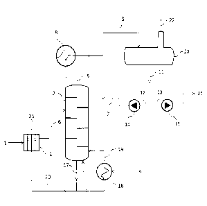
L'invention concerne un procédé pour le traitement d'un condensat de procédé (1) dans une usine d'ammoniac, l'usine d'ammoniac comprenant une section d'extrémité avant de production d'un gaz d'appoint et une section de synthèse où le gaz d'appoint est mis à réagir avec l'ammoniac, et ledit condensat de procédé (1) est recueilli dans un ou plusieurs équipements de l'usine d'ammoniac et est une solution aqueuse comportant de l'ammoniac, du dioxyde de carbone et du méthanol. Ledit procédé consiste : à revaporiser ledit condensat de procédé avec de la vapeur basse pression (4), à obtenir une phase vapeur (5) comprenant de l'ammoniac, du dioxyde de carbone et du méthanol extrait du condensat de procédé ; à condenser ladite phase vapeur, à obtenir une solution (11) enrichie en ammoniac et en méthanol ; à ré-introduire une première partie (12) de ladite solution audit environnement de ré-extraction ; à recycler une seconde partie (13) de ladite solution vers ladite usine d'ammoniac.


Abrégé anglais

A method for treatment of process condensate (1) in an ammonia plant, wherein the ammonia plant comprises a front-end section producing a make-up gas and a synthesis section where the make-up gas is reacted to ammonia, and said process condensate (1) is collected from one or more equipment of the ammonia plant and is an aqueous solution comprising ammonia,carbon dioxide and methanol. Said method comprises: stripping said process condensate with low-pressure steam (4), obtaining a vapour phase (5) comprising ammonia, carbon dioxide and methanol stripped from the process condensate; condensing said vapour phase, obtaining a solution (11) enriched of ammonia and methanol; re-introducing a first portion (12) of said solution to said stripping environment; recycling a second portion (13) of said solution to said ammonia plant.

Revendications

Note : Les revendications sont présentées dans la langue officielle dans laquelle elles ont été soumises.


8
CLAIMS:
1. A method for treatment of process condensate (1) in an ammonia plant,
wherein:
the ammonia plant comprises a front-end section producing a make-up
gas from reforming of a hydrocarbon source, and a synthesis section
where the make-up gas is reacted to ammonia;
said process condensate (1) is collected from one or more equipment of
the ammonia plant and is an aqueous solution comprising ammonia,
carbon dioxide and methanol,
the method being characterized by:
stripping of said process condensate in a stripping environment with low-
pressure steam (4) having a pressure of no more than 10 bar, obtaining a
vapour phase (5) comprising ammonia, carbon dioxide and methanol
stripped from the process condensate;
condensing said vapour phase, obtaining a condensate solution (11)
enriched of ammonia and methanol;
re-introducing a first portion (12) of said condensate solution (11) to said
stripping environment wherein said first portion (12) of solution is
reintroduced directly into said stripping environment;
recycling a second portion (13) of said condensate solution (11) to said
ammonia plant, wherein said second portion (13) is no more than 4% by
volume of said condensate solution (11).
2. A method according to claim 1, the pressure of said low-pressure steam
(4)
being 5 bar or less.
3. A method according to claim 2, wherein the pressure of said low-pressure

steam is in the range of 3 to 5 bar.
Date Recue/Date Received 2022-03-11

9
4. A niethod according to any one of claims 1 to 3, wherein said second
portion (13) of solution is recycled to the front-end section of the ammonia
plant.
5. A method according to claim 4, wherein said second portion (13) of
solution is recycled to a primary reformer of the front-end section of the
ammonia plant, where said solution is added to a process stream
subjected to reforming.
6. A method according to any one of claims 1 to 5, wherein said condensate
solution (11) contains 5 to 10 mol% of carbon dioxide, 3 to 8 mol% of
methanol and 7 to 13 mol% of ammonia.
7. A method according to claim 1, wherein said second portion (13) is no
more than 3% by volume of said condensate solution (11).
8. A method according to claim 1, wherein said second portion (13) is no
more than 2% by volume of said condensate solution (11).
9. A method according to claim 1, wherein said second portion is 2% by
volume or about 2% by volume of said condensate solution (11).
Date Recue/Date Received 2022-03-11

Description

Note : Les descriptions sont présentées dans la langue officielle dans laquelle elles ont été soumises.


CA 02986500 2017-11-20
WO 2016/184683 1
PCT/EP2016/059967
A method for increasing the capacity of an ammonia plant
DESCRIPTION
Field of the invention
The invention relates to the treatment of process condensate in a plant for
the
synthesis of ammonia.
Prior art
Ammonia is prepared starting from a make-up gas comprising hydrogen (H2)
and nitrogen (N2). Said make-up gas is conventionally produced by reforming a
hydrocarbon, such as natural gas, in a front-end section. The front end
section
includes a purification section, a reforming section and a syngas preparation
section. The purification section includes for example a desulphurization
converter, the reforming section may include a primary reformer and a
secondary reformer and the syngas preparation section generally comprises
one or more shift converters, a carbon dioxide removal section and a
methanator.
A front end for the production of the ammonia make-up gas is described for
example in EP 2 022 754 and EP 2 065 337.
The term "process condensate" denotes one or more by-product streams of
contaminated water collected from different locations of the plant. Said
process
condensate streams typically contain small (less than 1%) but not negligible
amounts of ammonia, carbon dioxide, methanol and other contaminants. Most
of the process condensate typically originates from the reforming section and
the syngas preparation section of the front-end, namely from a separator
before
the carbon dioxide removal section.
Due to the above contaminants, the process condensate cannot be discharged
as such. A prior art technique of treating the process condensate is stripping

CA 02986500 2017-11-20
WO 2016/184683 2
PCT/EP2016/059967
with a low-pressure stream to purify water and separate a gas containing
ammonia, CO2 and methanol; said gas is then flared or discharged as such. In
both cases, however, this technique introduces a further emission into
atmosphere. In order to avoid this drawback, the prior art provides an
alternative solution of stripping at a medium pressure, namely 25 ¨ 45 bar,
obtaining a gas phase under pressure which is then recycled to the front end.
This technique provides internal recycle of the ammonia, CO2 and methanol
contained in the process condensate but is expensive requiring equipment
under pressure.
US 5,385,646 discloses a method of treating a chemical production plant
process effluent aqueous stream of dilute contaminants which requires a
stripping section and a rectification section, for example arranged in a
tower,
which is however expensive.
Summary of the invention
The aim of the invention is to provide a novel technique for treatment of
process
condensate of ammonia plants, overcoming the above disadvantages of the
prior art.
This aim is reached with a method for treatment of process condensate in an
ammonia plant, wherein:
the ammonia plant comprises a front-end section producing a make-up gas
from reforming of a hydrocarbon source, and a synthesis section where the
make-up gas is reacted to ammonia;
said process condensate is collected from one or more equipment of the
ammonia plant and is an aqueous solution comprising ammonia, carbon dioxide
and methanol,
the method being characterized by:
stripping of said process condensate in a stripping environment with low-
pressure steam having a pressure of no more than 10 bar, obtaining a vapour

CA 02986500 2017-11-20
WO 2016/184683 3
PCT/EP2016/059967
phase comprising ammonia, carbon dioxide and methanol stripped from the
process condensate;
condensing said vapour phase, obtaining a condensate solution enriched of
ammonia and methanol;
re-introducing a first portion of said solution to said stripping environment
as
reflux;
recycling a second portion of said solution to said ammonia plant.
The pressure of the stripping steam is preferably 5 bar or less, more
preferably
3 to 4 bar.
Preferably said first portion of solution is reintroduced directly into the
stripping
environment. More specifically said first portion of solution is reintroduced
into
the stripping environment without a previous step of rectification, which is
not
required by the present invention.
The solution obtained after condensation is enriched of ammonia and methanol
compared to the incoming process condensate.
A portion of said solution is recycled to the ammonia plant. Preferably said
portion of the solution is recycled to the front-end section and added to the
process stream, i.e. to the stream subjected to reforming. To this purpose,
said
portion of solution is pumped to a suitable pressure, which is usually in the
range 25-45 bar (front-end pressure).
Preferably, said second portion of solution is no more than 4% of the
condensate solution, more preferably no more than 3% and even more
preferably no more than 2%.
In some embodiments the first portion of the above solution is 96 to 98 % and
the second portion is 2% to 4% of the condensate solution. In a preferred
embodiment said second portion is 2% to 3%, more preferably 2% or about 2%.
The above percentages are given by volume. Accordingly, the second portion of
solution contains a small fraction of the overhead vapours delivered by the
stripping process. Said second portion can also be termed distillate.

CA 02986500 2017-11-20
WO 2016/184683 4
PCT/EP2016/059967
An advantage of said distillate containing a small amount of the overall
vapour
from stripping, for example 2% or about 2%, is to reduce the drawback of
contamination of the process stream of the ammonia plant due to the
composition of the distillate. For example recycling a too large quantity of
overhead vapours to the stripping section, may lead to formation of undesired
compounds such as ammonium carbamate, due to the presence of water,
carbon dioxide and ammonia in the distillate, whilst a too large second
portion
of solution recycled to the ammonia plant would impact negatively the ammonia
plant front-end, due to the very high water content.
In a preferred embodiment, the front-end comprises a primary reformer and said

portion of solution is injected into the process side of the reformer.
Accordingly,
the ammonia, methanol and carbon dioxide are internally recycled and newly
steam reformed with production of hydrogen and carbon oxides, which can be
recycled, and carbon dioxide can be further separated in the CO2 separation
section.
The stripping of the process condensate is carried out for example in a
stripping
column. Vapours stripped from the column are condensed and sent to a
condensate reflux separator; the liquid phase drawn from the separator is the
above mentioned solution.
Preferably, said solution contains CO2 in the range 5 to 10 (Yo, methanol in
the
range 3 to 8 % and NH3 in the range 7 to 13 %. The concentration of said
solution is intended to be a molar concentration [mol %]. The applicant has
found that a concentration in this range is preferable to avoid formation of
solid
crystals and on the other hand to reduce cooling of the process stream after
injection which would be caused by excessive dilution.
The considerable advantage of the invention is that the treatment is carried
out
at a low pressure, thus requiring inexpensive equipment. In addition, thanks
to
the step of condensation, the recycle stream to the ammonia plant is liquid,
so
that recycling to the ammonia plant is easier and requires less energy

5
compared to recycling of a gaseous stream. A further advantage is that
emissions into atmosphere (particularly of CO2, NH3 and methanol) are avoided.
Another advantage is the ability to increase the capacity of the ammonia
plant,
in terms of quantity of ammonia produced. The increase is around 0.5% which
is small but still interesting from an economic point of view, being
obtainable
with a low investment cost.
Further aspects of the invention are a plant adapted to carry out the method
of
the invention, and a method of revamping.
A plant according to the invention is characterized by a section for treatment
of
the process condensate comprising at least a stripper, a condenser and a
pumping section. The stripper is fed with the process condensate and with low-
pressure steam as a stripping medium, said steam having preferably a pressure
of no more than 10 bar; the condenser receives a vapour phase comprising
ammonia, carbon dioxide and methanol from said stripper and produces a
solution enriched of ammonia and methanol; the pumping section is arranged to
re-introduce a first portion of said solution to said stripper and to recycle
a
second portion of said solution to said ammonia plant.
A revamping according to the invention is characterized by the provision of a
section for treatment of the process condensate including at least the above
mentioned equipment, namely stripper using low-pressure steam as a stripping
medium; condenser and pumping section to re-introduce a first portion of
solution to the stripper and to recycle a second portion of said solution to
the
ammonia plant.
The invention is attractive for revamping an existing plant because it
requires
the installation of relatively low-cost equipment such as low-pressure
stripping
column and distillate pumps, while it increases the production of ammonia and
eliminates a point of emission.
The method of the invention is now elucidated in a greater detail and with
reference to a preferred embodiment according to the scheme of Fig. 1.
Date Recue/Date Received 2022-03-11

CA 02986500 2017-11-20
WO 2016/184683 6
PCT/EP2016/059967
Detailed description
Fig. 1 shows a process condensate treatment section of an ammonia plant.
Stream 1 denotes a process condensate which is basically an aqueous solution
containing ammonia, methanol and carbon dioxide, in a concentration typically
of some thousands of ppm, and possibly traces of other contaminants such as
alcohols and other hydrocarbons.
Said process condensate 1 after pre-heating in a heat exchanger 2 is sent to a

stripping column 3 where it is contacted with a low-pressure stripping steam
4.
Said steam 4 is preferably at a pressure of 3 to 5 bar. The stripping column 3

receives pre-heated process condensate 6 and a recirculated solution 7 which
will be described later.
The overhead vapour 5 emerging from the stripping column 3 contains water,
ammonia, methanol and carbon dioxide stripped from the condensate 1. This
vapour 5 is condensed in a condenser 8, for example discharging the
condensation heat to water or steam, and the condensate 9 is sent to a
separator 10.
The liquid phase 11 drawn from said separator 10 is an ammonia-rich and
methanol-rich solution which is split into a first portion 12 and a second
portion
13.
The first portion 12 is sent back to the stripping column 3 via a first pump
14
which delivers the recirculated stream 7; the second portion 13 is recycled to

the ammonia plant via a second pump 15.
The first portion 12 is sent directly to the stripping column 3 via said pump
14.
The second portion 13 for example contains 2% or about 2% of the overhead
vapour 5.
Preferably said second portion 13 of the solution is recycled to a primary
reformer where it is injected into the process side of the reformer, i.e.
mixed
with the reforming gas. To this purpose, the second pump 15 delivers a liquid

7
stream 16 at the pressure of primary reforming, for example in the range 25 to

45 bar. This stream 16 can also be termed distilled stream.
The liquid 17 from bottom of the stripping column 3, which is purified water,
is
partly recirculated into the column 3 after passing through a reboiler 18. Re-
heated liquid 19 is introduced back into the lower part of the stripping
column 3.
Preferably, as shown, the reboiler 18 is heated by low-pressure stripping
steam
4. Said low-pressure stripping steam 4 can also be directly fed to the
stripping
column 3. The remaining portion 20 is preferably cooled in the process
condensate pre-heater 2 and the cooled purified water 21 is discharged or
exported.
The gas phase 22 from the separator 10 can be used e.g. as a fuel gas.
In a plant having a capacity of 1200 MTD (metric tonnes per day), wherein the
process condensate 1 contains about 1000 ppm of ammonia and 1000 ppm of
methanol, the recycle of stream 16 allows producing additional 4-5 MTD of
ammonia.
It must be noted that the invention can be used to revamp an existing plant
for
the synthesis of ammonia. A revamping according to the invention requires the
addition of the items of Fig. 1, plus auxiliaries such as piping, valves, etc.
which
in any case are not expensive. Hence the plant can be revamped at an
affordable cost. In some cases, a pre-existing treatment section based on
stripping and discharge into atmosphere or combustion of the stripped gas can
be modified to set-up a section arrangement similar to the one indicated in
Fig.1,
thus eliminating a polluting emission.
Date Recue/Date Received 2022-03-11

Dessin représentatif
Une figure unique qui représente un dessin illustrant l'invention.
États administratifs

Pour une meilleure compréhension de l'état de la demande ou brevet qui figure sur cette page, la rubrique Mise en garde , et les descriptions de Brevet , États administratifs , Taxes périodiques et Historique des paiements devraient être consultées.

États administratifs

Titre Date
Date de délivrance prévu 2023-02-28
(86) Date de dépôt PCT 2016-05-04
(87) Date de publication PCT 2016-11-24
(85) Entrée nationale 2017-11-20
Requête d'examen 2020-11-13
(45) Délivré 2023-02-28

Historique d'abandonnement

Il n'y a pas d'historique d'abandonnement

Taxes périodiques

Dernier paiement au montant de 277,00 $ a été reçu le 2024-04-18


 Montants des taxes pour le maintien en état à venir

Description Date Montant
Prochain paiement si taxe générale 2025-05-05 277,00 $
Prochain paiement si taxe applicable aux petites entités 2025-05-05 100,00 $

Avis : Si le paiement en totalité n'a pas été reçu au plus tard à la date indiquée, une taxe supplémentaire peut être imposée, soit une des taxes suivantes :

  • taxe de rétablissement ;
  • taxe pour paiement en souffrance ; ou
  • taxe additionnelle pour le renversement d'une péremption réputée.

Les taxes sur les brevets sont ajustées au 1er janvier de chaque année. Les montants ci-dessus sont les montants actuels s'ils sont reçus au plus tard le 31 décembre de l'année en cours.
Veuillez vous référer à la page web des taxes sur les brevets de l'OPIC pour voir tous les montants actuels des taxes.

Historique des paiements

Type de taxes Anniversaire Échéance Montant payé Date payée
Le dépôt d'une demande de brevet 400,00 $ 2017-11-20
Taxe de maintien en état - Demande - nouvelle loi 2 2018-05-04 100,00 $ 2017-11-20
Enregistrement de documents 100,00 $ 2017-12-05
Taxe de maintien en état - Demande - nouvelle loi 3 2019-05-06 100,00 $ 2019-04-18
Taxe de maintien en état - Demande - nouvelle loi 4 2020-05-04 100,00 $ 2020-04-23
Requête d'examen 2021-05-04 800,00 $ 2020-11-13
Taxe de maintien en état - Demande - nouvelle loi 5 2021-05-04 204,00 $ 2021-04-22
Taxe de maintien en état - Demande - nouvelle loi 6 2022-05-04 203,59 $ 2022-04-21
Taxe finale 2023-01-30 306,00 $ 2022-12-01
Taxe de maintien en état - brevet - nouvelle loi 7 2023-05-04 210,51 $ 2023-04-19
Taxe de maintien en état - brevet - nouvelle loi 8 2024-05-06 277,00 $ 2024-04-18
Titulaires au dossier

Les titulaires actuels et antérieures au dossier sont affichés en ordre alphabétique.

Titulaires actuels au dossier
CASALE SA
Titulaires antérieures au dossier
S.O.
Les propriétaires antérieurs qui ne figurent pas dans la liste des « Propriétaires au dossier » apparaîtront dans d'autres documents au dossier.
Documents

Pour visionner les fichiers sélectionnés, entrer le code reCAPTCHA :


Pour visualiser une image, cliquer sur un lien dans la colonne description du document. Pour télécharger l'image (les images), cliquer l'une ou plusieurs cases à cocher dans la première colonne et ensuite cliquer sur le bouton "Télécharger sélection en format PDF (archive Zip)" ou le bouton "Télécharger sélection (en un fichier PDF fusionné)".

Liste des documents de brevet publiés et non publiés sur la BDBC .

Si vous avez des difficultés à accéder au contenu, veuillez communiquer avec le Centre de services à la clientèle au 1-866-997-1936, ou envoyer un courriel au Centre de service à la clientèle de l'OPIC.


Description du
Document 
Date
(yyyy-mm-dd) 
Nombre de pages   Taille de l'image (Ko) 
Certificat électronique d'octroi 2023-02-28 1 2 527
Requête d'examen 2020-11-13 4 117
Demande d'examen 2021-11-19 3 192
Modification 2022-03-11 13 426
Revendications 2022-03-11 2 55
Description 2022-03-11 7 293
Taxe finale 2022-12-01 4 101
Dessins représentatifs 2023-01-31 1 6
Page couverture 2023-01-31 1 43
Abrégé 2017-11-20 1 62
Revendications 2017-11-20 3 126
Dessins 2017-11-20 1 24
Description 2017-11-20 7 287
Dessins représentatifs 2017-11-20 1 23
Traité de coopération en matière de brevets (PCT) 2017-11-20 5 240
Rapport prélim. intl. sur la brevetabilité reçu 2017-11-20 11 503
Rapport de recherche internationale 2017-11-20 3 71
Demande d'entrée en phase nationale 2017-11-20 3 104
Page couverture 2017-12-07 1 46