Sélection de la langue

Search

Sommaire du brevet 2987344 

Énoncé de désistement de responsabilité concernant l'information provenant de tiers

Une partie des informations de ce site Web a été fournie par des sources externes. Le gouvernement du Canada n'assume aucune responsabilité concernant la précision, l'actualité ou la fiabilité des informations fournies par les sources externes. Les utilisateurs qui désirent employer cette information devraient consulter directement la source des informations. Le contenu fourni par les sources externes n'est pas assujetti aux exigences sur les langues officielles, la protection des renseignements personnels et l'accessibilité.

Disponibilité de l'Abrégé et des Revendications

L'apparition de différences dans le texte et l'image des Revendications et de l'Abrégé dépend du moment auquel le document est publié. Les textes des Revendications et de l'Abrégé sont affichés :

  • lorsque la demande peut être examinée par le public;
  • lorsque le brevet est émis (délivrance).
(12) Demande de brevet: (11) CA 2987344
(54) Titre français: SYSTEME ET METHODE DE DETECTION DE DEFAILLANCE DANS UN CAPTEUR DE PRESSION D'UN SYSTEME DE POMPE INCENDIE
(54) Titre anglais: SYSTEM AND METHOD FOR DETECTING FAILURE IN A PRESSURE SENSOR OF A FIRE PUMP SYSTEM
Statut: Réputée abandonnée
Données bibliographiques
Abrégés

Abrégé anglais


An automatic failure detecting device for detecting failure in a pressure
sensor for a
fire pump controller, the failure detecting device comprising a three-way
valve
connecting the pressure sensor to a water line, wherein when the three-way
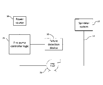
valve is
activated, the pressure sensor is exposed to the atmosphere to measure the
atmospheric pressure, and wherein the failure detection device signals a fault
if said
measured atmospheric pressure differs from a standard expected value.

Revendications

Note : Les revendications sont présentées dans la langue officielle dans laquelle elles ont été soumises.


5
CLAIMS
1. An automatic failure detecting device for detecting failure in a
pressure sensor
for a fire pump controller, the failure detecting device comprising a three-
way valve
connecting the pressure sensor to a water line, wherein when said three-way
valve is
activated, the pressure sensor is exposed to the atmosphere to measure the
atmospheric pressure, and wherein the failure detection device signals a fault
if said
measured atmospheric pressure differs from a standard expected value.
2. A method for automatically detecting failure in a pressure sensor for a
fire
pump controller, the method comprising the steps of:
exposing the pressure sensor to the atmosphere by activating a three-way
valve connecting the pressure sensor to a water line;
measuring an atmospheric pressure;
comparing said measured atmospheric pressure to a standard expected
value; and
signaling a fault if said measured atmospheric pressure and said standard
reading differ.
3. The method of claim 2, wherein the pressure sensor is exposed to the
atmosphere once per day.

Description

Note : Les descriptions sont présentées dans la langue officielle dans laquelle elles ont été soumises.

1
SYSTEM AND METHOD FOR DETECTING FAILURE IN A PRESSURE SENSOR
OF A FIRE PUMP SYSTEM
TECHNICAL FIELD
[001] The present disclosure concerns automatic failure detection in a
pressure
sensor of a fire pump controller.
BACKGROUND OF THE INVENTION
[002] Fire pumps are needed when local municipal water systems, for example
public underground water supplies, tanks, reservoirs and lakes, cannot provide
sufficient pressure to meet the hydraulic design requirements of a fire
sprinkler
system. This usually occurs if a building is very tall, or if the system
requires a
relatively high terminal pressure at the fire sprinklers in order to provide
large
volumes of water, such as in storage warehouses. Fire pumps are also needed
when
the water supply is provided by a ground level water storage tank.
[003] Fire pump controllers are usually equipped with a pressure sensor that
is
responsible for activating the pump in case of fire. The pressure sensor
senses the
water pressure in the sprinkler system's water line. In the event of a fire,
the sprinkler
system activates to spray water, thus lowering the water pressure in the water
line.
The fire pump controller is configured to activate the fire pump in the event
that the
pressure in the water line drops below an activation threshold, and to stop
the pump
when the water pressure rises above a stopping threshold. A proper working
sensor
is vital to the functioning of the fire system, and is thus a critical
component.
[004] Unfortunately, sensors have often been the subject of material or
manufacturing problems. A noted defect is an offset in the response of the
sensor
under pressure, either downwards or upwards, while still maintaining the
correct
linearity of the response profile. Such a situation is dire, as a change in
the response
of a sensor can cause untimely activations of the pump, or worse, prevent its
activation in the event of an actual pressure drop.
[005] To resolve the above-mentioned problem, certain fire pump controllers
have
been equipped with a second redundant pressure sensor to corroborate the
information provided by the main sensor. If the two readings are not the same,
the
system is notified. This technique suffers from certain drawbacks: there is a
cost
associated with adding a second sensor, and more importantly, it is extremely
difficult
to determine which of the two sensors is the faulty one.
CA 2987344 2017-11-30

2
SUMMARY OF THE INVENTION
[006] It is an object of the present disclosure to provide automatic failure
detection
in a pressure sensor for a fire pump controller that requires no additional
redundant
pressure sensor and allows for the detection of a faulty sensor with greater
precision.
[007] Accordingly, the present disclosure provides an automatic failure
detecting
device for detecting failure in a pressure sensor for a fire pump controller,
the failure
detecting device comprising a three-way valve connecting the pressure sensor
to a
water line, wherein when the three-way valve is activated, the pressure sensor
is
exposed to the atmosphere to measure the atmospheric pressure, and wherein the
failure detection device signals a fault if said measured atmospheric pressure
differs
from a standard expected value.
[008] There is also provided a method for automatically detecting failure in a
pressure sensor for a fire pump controller, the method comprising the steps of
exposing the pressure sensor to the atmosphere by activating a three-way valve
connecting the pressure sensor to a water line, measuring an atmospheric
pressure,
comparing the measured atmospheric pressure to a standard expected value, and
signaling a fault if the measured atmospheric pressure and the standard
reading
differ.
[009] In an embodiment, the pressure sensor is exposed to the atmosphere once
per day.
[0010] All of the foregoing and still further objects and advantages of the
invention
will become apparent from a study of the following specification, taken in
connection
with the accompanying drawings wherein like characters of reference designate
corresponding parts throughout the several views.
BRIEF DESCRIPTION OF THE FIGURES
[0011] Embodiments of the disclosure will be described by way of examples only
with reference to the accompanying drawing, in which:
[0012] FIG. 1 is a graphical depiction of various pressure sensor response
times;
[0013] FIG. 2A is a sketch of a failure detection device in an OFF state, in
accordance with an illustrative embodiment of the present invention;
[0014] FIG. 2B is a sketch of a failure detection device in an ON state, in
accordance
with an illustrative embodiment of the present invention;
CA 2987344 2017-11-30

3
[0015] FIG. 3 is a graphical depiction of a pressure reading taken by the
failure
detection device of FIG. 26, in accordance with an illustrative embodiment of
the
present invention; and
[0016] FIG. 4 is a schematic diagram of a fire pump controller system, in
accordance
with an illustrative embodiment of the present invention.
DETAILED DESCRIPTION
[0017] Referring to FIG. 1, there is shown a pressure-time graph for various
pressure
sensor readings in a typical fire pump system. For a properly functioning
sensor,
depicted by the curve "good sensor", the pump motor is activated when the
water
pressure in the water line drops below a "start" value (due to the sprinkler
system
activating) and deactivates when the pressure in the water line rises back
above a
"stop" value, signifying that the sprinkler system is no longer being used and
the
pump has brought the water pressure up to a suitable value. For a faulty
sensor with
an upwardly offset pressure response, depicted by the curve "bad sensor 1", a
drop
in pressure may never fall below the "start" value, and thus the motor will
not activate
in the case of a fire. In such a case, the water pressure will remain constant
at a
value lower than that required for the sprinkler system to be effective.
Alternatively,
for a faulty sensor with a downwardly offset pressure response, the pressure
reading
may drop low enough to initiate the pump, but never rise above the "stop
value",
causing the pump to run continuously, eventually breaking. Therefore, it is
thus
crucial to ensure that the pressure sensor being used is providing accurate
readings.
[0018] Referring now to FIG. 2A, there is shown a failure detection device,
generally
referred to by the reference numeral 10, in its OFF state. A three-way valve
12
positioned in the water line 14 replaces the standard valve (often a solenoid
valve)
typically found in fire pump controllers for creating a leak in the line of
pressure to
perform a start-up test. The three-way valve 12 comprises an inlet 16 for
receiving
water from the water line 14, a main outlet 18 directed towards the sprinkler
system
(not shown), a drain outlet 20 directed towards a drain (not shown), and a
pressure
sensor 22 or pressure transducer "PT". In its OFF state, the three-way valve
12
directs water from the inlet 16 to the main outlet 18, and the pressure sensor
22
records the pressure of the water entering the failure detection device 10
from the
water line.
[0019] Referring now to FIG. 2B, the failure detection device 10 is shown in
its ON
state. In this state, the three-way valve 12 is configured to direct water
from the water
CA 2987344 2017-11-30

4
line 14 entering the failure detection device 10 from the inlet 16 to the
drain outlet 20
rather than the main outlet 18. In this configuration, the pressure sensor 22
is
disconnected from the water line 14 and exposed to the atmosphere. Thus, the
pressure sensor 20 may record pressure readings at atmospheric pressure.
[0020] Referring now to FIG. 3 in addition to FIG.'s 2A and 2B, a pressure-
time
graph displays pressure readings for various states of the failure detection
device 10.
During the OFF states, the pressure sensor 22 reads the pressure of the water
passing through the failure detection device 10 from the main line 14, which
remains
consistent as long as the sprinkler system (not shown) is not activated.
During the
ON state, the pressure sensor 22 is exposed to the atmosphere, and thus
records
the atmospheric pressure. In an embodiment, the pressure sensor 22 is
calibrated to
read 0 PSI at atmospheric pressure. As such, in order to periodically test the
accuracy of the pressure sensor 22, the failure detection device 10 is
switched to its
ON state by activating the three-way valve 12 and exposing the pressure sensor
22
to the atmosphere. If the pressure sensor 22 provides a reading of 0 PSI, then
it is
functioning properly. If the pressure sensor 22 does not provide a reading of
0 PSI,
then failure has been detected and the faulty pressure sensor 22 may be
replaced. In
an embodiment, this test is performed daily or weekly to ensure constant
surveillance
of the pressure sensor.
[0021] Referring now to FIG. 4, the failure detection device 10 is connected
to a fire
pump controller logic 24. Receiving power from a power source 26, the fire
pump
controller logic receives input from the failure detection device 10 regarding
the water
pressure in the water line 14. The fire pump controller 24 activates a fire
pump 28
when a drop in pressure in the water line 14 is detected due to activation of
a
sprinkler system 30. When the failure detection device 10 detects failure in
the
pressure sensor (not shown), it alerts the fire pump controller logic 22.
[0022] The scope of the claims should not be limited by the preferred
embodiments
set forth in the examples, but should be given the broadest interpretation
consistent
with the description as a whole.
CA 2987344 2017-11-30

Dessin représentatif
Une figure unique qui représente un dessin illustrant l'invention.
États administratifs

2024-08-01 : Dans le cadre de la transition vers les Brevets de nouvelle génération (BNG), la base de données sur les brevets canadiens (BDBC) contient désormais un Historique d'événement plus détaillé, qui reproduit le Journal des événements de notre nouvelle solution interne.

Veuillez noter que les événements débutant par « Inactive : » se réfèrent à des événements qui ne sont plus utilisés dans notre nouvelle solution interne.

Pour une meilleure compréhension de l'état de la demande ou brevet qui figure sur cette page, la rubrique Mise en garde , et les descriptions de Brevet , Historique d'événement , Taxes périodiques et Historique des paiements devraient être consultées.

Historique d'événement

Description Date
Réputée abandonnée - omission de répondre à une demande de l'examinateur 2024-02-05
Rapport d'examen 2023-10-03
Inactive : Rapport - Aucun CQ 2023-09-18
Lettre envoyée 2022-08-16
Requête d'examen reçue 2022-07-21
Exigences pour une requête d'examen - jugée conforme 2022-07-21
Toutes les exigences pour l'examen - jugée conforme 2022-07-21
Représentant commun nommé 2020-11-07
Représentant commun nommé 2019-10-30
Demande publiée (accessible au public) 2019-05-30
Inactive : Page couverture publiée 2019-05-29
Inactive : Regroupement d'agents 2018-09-01
Demande visant la nomination d'un agent 2018-08-30
Inactive : Regroupement d'agents 2018-08-30
Demande visant la révocation de la nomination d'un agent 2018-08-30
Inactive : CIB attribuée 2018-05-14
Inactive : CIB en 1re position 2018-05-14
Inactive : CIB attribuée 2018-05-14
Inactive : Certificat dépôt - Aucune RE (bilingue) 2017-12-08
Lettre envoyée 2017-12-07
Demande reçue - nationale ordinaire 2017-12-06

Historique d'abandonnement

Date d'abandonnement Raison Date de rétablissement
2024-02-05

Taxes périodiques

Le dernier paiement a été reçu le 2023-09-13

Avis : Si le paiement en totalité n'a pas été reçu au plus tard à la date indiquée, une taxe supplémentaire peut être imposée, soit une des taxes suivantes :

  • taxe de rétablissement ;
  • taxe pour paiement en souffrance ; ou
  • taxe additionnelle pour le renversement d'une péremption réputée.

Les taxes sur les brevets sont ajustées au 1er janvier de chaque année. Les montants ci-dessus sont les montants actuels s'ils sont reçus au plus tard le 31 décembre de l'année en cours.
Veuillez vous référer à la page web des taxes sur les brevets de l'OPIC pour voir tous les montants actuels des taxes.

Historique des taxes

Type de taxes Anniversaire Échéance Date payée
Taxe pour le dépôt - générale 2017-11-30
Enregistrement d'un document 2017-11-30
TM (demande, 2e anniv.) - générale 02 2019-12-02 2019-11-25
TM (demande, 3e anniv.) - générale 03 2020-11-30 2020-09-14
TM (demande, 4e anniv.) - générale 04 2021-11-30 2021-07-26
Requête d'examen - générale 2022-11-30 2022-07-21
TM (demande, 5e anniv.) - générale 05 2022-11-30 2022-08-01
TM (demande, 6e anniv.) - générale 06 2023-11-30 2023-09-13
Titulaires au dossier

Les titulaires actuels et antérieures au dossier sont affichés en ordre alphabétique.

Titulaires actuels au dossier
TORNATECH INC.
Titulaires antérieures au dossier
FRANCOIS HARVEY
MARC GOUPIL
Les propriétaires antérieurs qui ne figurent pas dans la liste des « Propriétaires au dossier » apparaîtront dans d'autres documents au dossier.
Documents

Pour visionner les fichiers sélectionnés, entrer le code reCAPTCHA :


Pour visualiser une image, cliquer sur un lien dans la colonne description du document. Pour télécharger l'image (les images), cliquer l'une ou plusieurs cases à cocher dans la première colonne et ensuite cliquer sur le bouton "Télécharger sélection en format PDF (archive Zip)" ou le bouton "Télécharger sélection (en un fichier PDF fusionné)".

Liste des documents de brevet publiés et non publiés sur la BDBC .

Si vous avez des difficultés à accéder au contenu, veuillez communiquer avec le Centre de services à la clientèle au 1-866-997-1936, ou envoyer un courriel au Centre de service à la clientèle de l'OPIC.


Description du
Document 
Date
(aaaa-mm-jj) 
Nombre de pages   Taille de l'image (Ko) 
Abrégé 2017-11-29 1 12
Description 2017-11-29 4 201
Dessins 2017-11-29 5 48
Revendications 2017-11-29 1 24
Dessin représentatif 2019-04-29 1 4
Certificat de dépôt 2017-12-07 1 201
Courtoisie - Certificat d'enregistrement (document(s) connexe(s)) 2017-12-06 1 101
Courtoisie - Lettre d'abandon (R86(2)) 2024-04-14 1 569
Rappel de taxe de maintien due 2019-07-30 1 111
Courtoisie - Réception de la requête d'examen 2022-08-15 1 423
Demande de l'examinateur 2023-10-02 4 209
Requête d'examen 2022-07-20 3 76