Sélection de la langue

Search

Sommaire du brevet 2987454 

Énoncé de désistement de responsabilité concernant l'information provenant de tiers

Une partie des informations de ce site Web a été fournie par des sources externes. Le gouvernement du Canada n'assume aucune responsabilité concernant la précision, l'actualité ou la fiabilité des informations fournies par les sources externes. Les utilisateurs qui désirent employer cette information devraient consulter directement la source des informations. Le contenu fourni par les sources externes n'est pas assujetti aux exigences sur les langues officielles, la protection des renseignements personnels et l'accessibilité.

Disponibilité de l'Abrégé et des Revendications

L'apparition de différences dans le texte et l'image des Revendications et de l'Abrégé dépend du moment auquel le document est publié. Les textes des Revendications et de l'Abrégé sont affichés :

  • lorsque la demande peut être examinée par le public;
  • lorsque le brevet est émis (délivrance).
(12) Demande de brevet: (11) CA 2987454
(54) Titre français: TONDEUSE POUSSEE AVEC COMMANDE A VOLANT DE DIRECTION
(54) Titre anglais: WALK-BEHIND MOWER WITH STEERING WHEEL CONTROL
Statut: Réputée abandonnée et au-delà du délai pour le rétablissement - en attente de la réponse à l’avis de communication rejetée
Données bibliographiques
(51) Classification internationale des brevets (CIB):
  • A01D 34/68 (2006.01)
  • A01D 34/81 (2006.01)
  • A01D 34/82 (2006.01)
(72) Inventeurs :
  • WOODRUM, ADAM (Etats-Unis d'Amérique)
(73) Titulaires :
  • MTD PRODUCTS INC
(71) Demandeurs :
  • MTD PRODUCTS INC (Etats-Unis d'Amérique)
(74) Agent: DEETH WILLIAMS WALL LLP
(74) Co-agent:
(45) Délivré:
(86) Date de dépôt PCT: 2016-06-06
(87) Mise à la disponibilité du public: 2016-12-08
Requête d'examen: 2021-06-02
Licence disponible: S.O.
Cédé au domaine public: S.O.
(25) Langue des documents déposés: Anglais

Traité de coopération en matière de brevets (PCT): Oui
(86) Numéro de la demande PCT: PCT/US2016/036044
(87) Numéro de publication internationale PCT: US2016036044
(85) Entrée nationale: 2017-11-24

(30) Données de priorité de la demande:
Numéro de la demande Pays / territoire Date
62/171,732 (Etats-Unis d'Amérique) 2015-06-05

Abrégés

Abrégé français

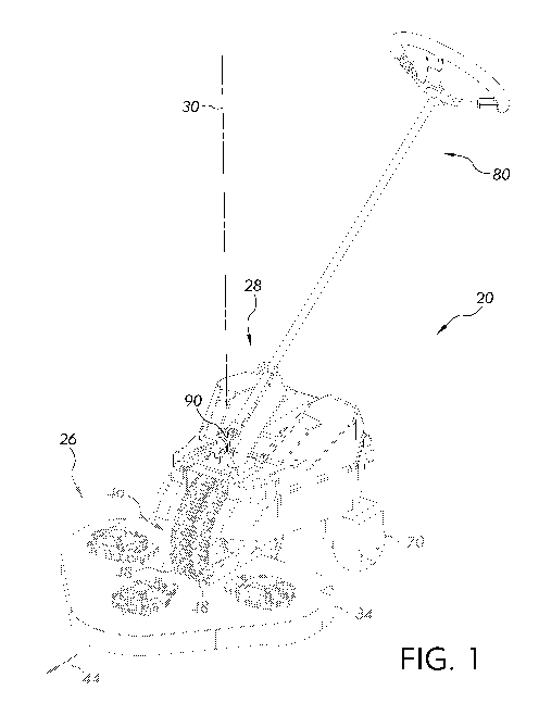
Selon l'invention, une tondeuse poussée (20) comprend un châssis (24) et une source d'énergie (50) attachée au châssis (24). Une roue d'entraînement orientable sélectivement (46) et un ensemble de roues secondaires (70) sont fixées sur le cadre (24) de façon à pouvoir tourner. La tondeuse poussée (20) comprend un ensemble volant de direction (80) attaché au châssis (24), l'ensemble contenant une colonne de direction (84) et un volant de direction (86) attaché à la colonne de direction (84). La tondeuse poussée (20) contient aussi un joint de cardan (90) raccordant l'ensemble volant de direction (80) au châssis (24). La tondeuse poussée (20) comprend aussi un tablier de tondeuse (34) attaché au châssis (24) et un ensemble lame de tondeuse (36) attaché au tablier. Dans d'autres exemples, la tondeuse poussée (20) comprend une section avant (26) et une section arrière (28) qui tournent l'une par rapport à l'autre autour d'un axe vertical (30).


Abrégé anglais

A walk-behind mower (20) includes a frame (24) and a power source (50) attached to the frame (24). A selectively steerable drive wheel (46) and a set of follower wheels (70) are rotatably attached to the frame (24). The walk-behind mower (20) includes a steering wheel assembly (80) attached to the frame (24), the assembly including a steering column (84) and a steering wheel (86) attached to the steering column (84). The walk-behind mower (20) also includes a universal joint (90) connecting the steering wheel assembly (80) to the frame (24). The walk-behind mower (20) further includes a mower deck (34) attached to the frame (24) and a mower blade assembly (36) attached to the deck. In other examples, the walk-behind mower (20) includes a front section (26) and a rear section (28) that rotate relative to each other about a vertical axis (30).

Revendications

Note : Les revendications sont présentées dans la langue officielle dans laquelle elles ont été soumises.


7
CLAIMS
1. A walk-behind mower, said walk-behind mower comprising:
a frame;
a power source attached to said frame;
a selectively steerable drive wheel rotatably attached to said frame;
a set of follower wheels attached to said frame;
a steering wheel assembly attached to said frame, said steering wheel
assembly comprising:
a steering column;
a steering wheel attached to said steering column;
a universal j oint connecting said steering wheel assembly to said frame;
a mower deck attached to said frame; and
a mower blade assembly attached to said deck.
2. The walk-behind mower according to claim 1, wherein said steering wheel
assembly applies a force to said frame on a vertical axis passing through said
selectively steerable drive wheel.
3. The walk-behind mower according to claim 2, wherein said vertical axis
is co-
linear with a vertical centerline of said steerable drive wheel.
4. The walk-behind mower according to claim 1, wherein said mower blade
assembly further comprises a high-efficiency blade system.
5. The walk-behind mower according to claim 1, further including a front
section
and a rear section.
6. The walk-behind mower according to claim 5, wherein said front section
and
said rear section are rotatably connected to each other.
7. The walk-behind mower according to claim 6, wherein one of said front
section and said rear section is configured to rotate relative to the other of
said front
section and said rear section about a vertical axis.

8
8. The walk-behind mower according to claim 7, wherein one of said front
section and said rear section is configured to rotate relative to the other of
said front
section and said rear section about a centerline of said selectively steerable
drive
wheel.

Description

Note : Les descriptions sont présentées dans la langue officielle dans laquelle elles ont été soumises.


CA 02987454 2017-11-24
WO 2016/197120
PCT/US2016/036044
1
WALK-BEHIND MOWER WITH STEERING WHEEL CONTROL
CROSS-REFERENCE TO RELATED APPLICATIONS
[0001] This application is related to U.S. Provisional Patent Application
Serial
No. 62/171,732, filed June 5, 2015, which is hereby fully incorporated herein.
BACKGROUND
1. Field Of The Disclosure
[0002] The present disclosure is directed to mowers and more particularly,
a
walk-behind mower with steering wheel control.
2. Description of Related Art
[0003] Some known mowers have rigid controls such as a handle that require
the
operator to walk around obstacles and U-turns with the handle of the mower.
This
can cause unnecessary walking during turns and avoidance of obstacles for the
operator.
[0004] Accordingly, there is a need for a mower that can be easily
controlled with
a steering wheel.
SUMMARY
[0005] According to one embodiment of the present disclosure, a walk-behind
mower includes a frame and a power source attached to the frame. The walk-
behind
mower also includes a selectively steerable drive wheel rotatably attached to
said
frame. The walk-behind mower further includes a set of follower wheels
attached to
the frame. The walk-behind mower still further includes a steering wheel
assembly
attached to the frame. The steering wheel assembly includes a steering column
and a
steering wheel attached to the steering column. The walk-behind mower also
includes
a universal joint connecting the steering wheel assembly to the frame. The
walk-
behind mower further includes a mower deck attached to the frame and a mower
blade assembly attached to the deck.
[0006] Advantages of the present disclosure will become more apparent to
those
skilled in the art from the following description of the embodiments of the
disclosure
which have been shown and described by way of illustration. As will be
realized, the

CA 02987454 2017-11-24
WO 2016/197120
PCT/US2016/036044
2
described apparatus and method are capable of other and different embodiments,
and
their details are capable of modification in various respects.
BRIEF DESCRIPTION OF THE DRAWINGS
[0007] These and other features of the present disclosure, and their
advantages,
are illustrated specifically in embodiments of the disclosure now to be
described, by
way of example, with reference to the accompanying diagrammatic drawings, in
which:
[0008] FIG. 1 is a perspective view of an embodiment of a mower of the
present
disclosure;
[0009] FIG. 2 is a top view of the mower of FIG. 1;
[0010] detail view of the mower of FIG. 1, showing the underside of the
deck;
[0011] FIG. 3 is an elevation view of the mower of FIG. 1;
[0012] FIG. 4 is an underside of the mower of FIG. 1;
[0013] FIG. 5 is a cross-section view taken along line 5-5 of FIG. 3; and
[0014] FIG. 6 is a top view of the mower showing the turning effect of the
mower.
[0015] It should be noted that all the drawings are diagrammatic and not
drawn to
scale. Relative dimensions and proportions of parts of these figures may have
been
shown exaggerated or reduced in size for the sake of clarity and convenience
in the
drawings. The same reference numbers are generally used to refer to
corresponding
or similar features in the different embodiments. Accordingly, the drawing(s)
and
description are to be regarded as illustrative in nature and not as
restrictive.
DETAILED DESCRIPTION
[0016] Example embodiments that incorporate one or more aspects of the
present
disclosure are described and illustrated in the drawings. These illustrated
examples
are not intended to be a limitation on the present disclosure. For example,
one or
more aspects of the present disclosure can be utilized in other embodiments
and even
other types of devices. Moreover, certain terminology is used herein for
convenience
only and is not to be taken as a limitation on the present disclosure. Still
further, in
the drawings, the same reference numerals are employed for designating the
same
elements.

CA 02987454 2017-11-24
WO 2016/197120
PCT/US2016/036044
3
[0017] Turning to FIG. 1, an embodiment of a walk-behind mower 20 with
steering wheel control is shown with a perspective view. The mower 20 includes
a
frame 24 that is constructed to provide a framework for many of the components
of
the mower 20. In broad terms, the mower 20 includes two sections, a front
section 26
and a rear section 28. The front section 26 is rotatably attached to the rear
section 28
about a vertical axis 30. As such, one of the front section 26 and rear
section 28 can
be rotated about the vertical axis 30 to create a steering effect.
[0018] The front section 26 includes a mower deck 34 that houses at least
one
mower blade assembly 36 (best seen in FIGS. 4 and 5). In one example, the
mower
blade assembly 36 can include solid, one-piece blades similar to typical lawn
mower
blades. In another example, the mower blade assembly 36 can include a dome-
like
shell 38 having a plurality of cutting blades 40 attached to the shell 38. In
a particular
example, the mower blade assembly 36 can include a high-efficiency blade
assembly
similar to or the same as the blade system further described in U.S. Patent
Application
having Serial No. 62/325,159 and related applications. It is to be understood
that
other, similar systems can also be used such as the blade system as described
in U.S.
Patent Application having Serial No. 15/166,378 and related applications.
Additionally, as shown best in FIG. 5, the mower blade assemblies 36 can
differ from
each other when multiple mower blade assemblies 36 are utilized. These mower
blade assemblies 36 can also have a path overlap, such that as the mower 20
travels in
a forward direction (represented by arrow 44), the cutting paths of at least
two mower
blade assemblies 36 can cover some of the same vegetation (e.g., grass) to be
cut.
[0019] In one example, the mower blade assembly 36 can be "quick-change,"
in
other words requires no additional tools to attach and/or detach the mower
blade
assembly 36 from the mower 20. In another example, the individual cutting
blades 40
can be quick-change blades. The described blade assemblies can greatly reduce
the
required power to rotate the cutting blades 40. Furthermore, the described
blade
assemblies 36 can increase battery run-time.
[0020] The front section 26 also includes a selectively steerable drive
wheel 46.
In the shown example, the selectively steerable drive wheel 46 includes two
wheels
48. The selectively steerable drive wheel 46 is configured to turn about the
vertical
axis 30. The mower deck 34 is also connected to the selectively steerable
drive wheel

CA 02987454 2017-11-24
WO 2016/197120
PCT/US2016/036044
4
46 such that as the selectively steerable drive wheel 46 rotates about the
vertical axis
30, the mower deck rotates at the same rate.
[0021] The rear section 28 includes the frame 24 as shown in FIG. 4. A
power
source 50 can be attached to the frame 24. In the shown example the power
source 50
is a battery or batteries 50 that are rechargeable. Turning to FIG. 5, the
batteries
provide electrical power for at least one electric drive motor 60 and at least
one
electric blade motor 64. In another embodiment, the power source 50 is an
internal
combustion engine. It should be understood by one having ordinary skill that
the
power source 50 can be any prime mover that is powered by fuel, electricity,
or a
hybrid-electric drive.
[0022] Power from the power source 50 enables operation of the electric
drive
motor 60. The electric drive motor is attached to the selectively steerable
drive wheel
46 such that rotation of the electric drive motor 60 urges rotation of the
selectively
steerable drive wheel 46. As an associated operator calls for rotation of the
selectively steerable drive wheel 46, power from the power source 50 rotates
the
electric drive motor. As can be appreciated, the signal for rotation can be
varied to
create a continuous range of acceleration within an upper limit and a lower
limit.
[0023] As will be understood, the mower 20 includes an electric blade motor
64
for each mower blade assembly 36. In the shown example, the electric blade
motors
64 are located on the top of the mower deck 34 and include a motor shaft 66
that
passes through the mower deck 34. Each mower blade assembly 36 is attached to
a
motor shaft 66 such that rotation of the motor shaft 66 effects rotation of
the mower
blade assembly 36 in a desired forward or reverse direction.
[0024] The rear section 28 further includes a set of follower wheels 70
(e.g.,
caster wheels) attached to the frame 24. In one example, the follower wheels
70 are
located in a rearward direction from the selectively steerable drive wheel 46.
The
shown example includes two follower wheels 70 to create a three-point base of
wheels to support the frame 24 of the mower 20.
[0025] The mower 20 also includes a steering wheel assembly 80 attached to
the
frame 24 and the front section 26. As shown, the steering wheel assembly 80
includes
a steering column 84 which extends upward and rearwardly for convenient use by
an
associated operator. The steering column 84 supports a steering wheel 86 which
is
attached thereto. The steering wheel 86 can include any number of controls
such as

CA 02987454 2017-11-24
WO 2016/197120
PCT/US2016/036044
blade on/off, forward/reverse direction, accelerator, operator presence
control, etc. In
one example, the steering column 84 can be located inside a hollow shaft 88.
Operator rotation of the steering wheel 86 applies a rotational force to the
steering
column 84 to rotate the steering column 84.
[0026] The steering column 84 is attached to the frame 24 with a universal
joint
90 such that when a rotational force is applied to the steering column 84, the
rotational force causes the rear section 28 of the mower 20 to swing to the
right or the
left, represented by arrow 94, thereby steering the mower 20. In a particular
example,
the universal j oint 90 is mounted directly above the selectively steerable
drive wheel
46. In a more particular example, a centerline of a portion of the universal
joint 90 is
co-linear with the vertical axis 30. As such, the steering wheel assembly 80
applies a
turning force to the frame 24 about the vertical axis 30 passing through the
selectively
steerable drive wheel 46. In a more particular example, the vertical axis 30
is co-
linear with a centerline of the selectively steerable drive wheel 46.
[0027] The described mower can provide several benefits, one being the
ability to
turn the mower without having to follow the rear (such as behind a push handle
on a
typical walk-behind mower), thereby saving walking distance and energy for the
operator. Another benefit can include a relatively tight turning radius for
the mower
to maneuver the mower about obstacles in a desired grass cutting path. Yet
another
benefit can include a 180 turn while the associated operator remains in the
same
general location.
[0028] While this disclosure has been written in conjunction with the
specific
embodiments described above, it is evident that many alternatives,
combinations,
modifications and variations are apparent to those skilled in the art.
Accordingly, the
described embodiments of this disclosure, as set forth above are intended to
be
illustrative only, and not in a limiting sense. Various changes can be made
without
departing from the spirit and scope of this disclosure. Combinations of the
above
embodiments and other embodiments will be apparent to those of skill in the
art upon
studying the above description and are intended to be embraced therein.
Therefore,
the scope of the present disclosure is defined by the appended claims, and all
devices,
processes, and methods that come within the meaning of the claims, either
literally or
by equivalence, are intended to be embraced therein. Furthermore, to the
extent that
the term "includes" is used in either the detailed description or the claims,
such term

CA 02987454 2017-11-24
WO 2016/197120
PCT/US2016/036044
6
is intended to be inclusive in a manner similar to the term "comprising" as
"comprising" is interpreted when employed as a transitional word in a claim.

Dessin représentatif
Une figure unique qui représente un dessin illustrant l'invention.
États administratifs

2024-08-01 : Dans le cadre de la transition vers les Brevets de nouvelle génération (BNG), la base de données sur les brevets canadiens (BDBC) contient désormais un Historique d'événement plus détaillé, qui reproduit le Journal des événements de notre nouvelle solution interne.

Veuillez noter que les événements débutant par « Inactive : » se réfèrent à des événements qui ne sont plus utilisés dans notre nouvelle solution interne.

Pour une meilleure compréhension de l'état de la demande ou brevet qui figure sur cette page, la rubrique Mise en garde , et les descriptions de Brevet , Historique d'événement , Taxes périodiques et Historique des paiements devraient être consultées.

Historique d'événement

Description Date
Demande non rétablie avant l'échéance 2023-12-06
Le délai pour l'annulation est expiré 2023-12-06
Lettre envoyée 2023-06-06
Réputée abandonnée - omission de répondre à un avis sur les taxes pour le maintien en état 2022-12-06
Lettre envoyée 2022-06-06
Lettre envoyée 2021-06-11
Exigences pour une requête d'examen - jugée conforme 2021-06-02
Toutes les exigences pour l'examen - jugée conforme 2021-06-02
Requête d'examen reçue 2021-06-02
Représentant commun nommé 2020-11-07
Inactive : COVID 19 - Délai prolongé 2020-05-28
Représentant commun nommé 2019-10-30
Requête visant le maintien en état reçue 2019-05-23
Requête visant le maintien en état reçue 2018-05-25
Inactive : Page couverture publiée 2017-12-15
Inactive : Notice - Entrée phase nat. - Pas de RE 2017-12-14
Inactive : CIB en 1re position 2017-12-12
Inactive : CIB attribuée 2017-12-07
Demande reçue - PCT 2017-12-07
Exigences pour l'entrée dans la phase nationale - jugée conforme 2017-11-24
Demande publiée (accessible au public) 2016-12-08

Historique d'abandonnement

Date d'abandonnement Raison Date de rétablissement
2022-12-06

Taxes périodiques

Le dernier paiement a été reçu le 2021-05-28

Avis : Si le paiement en totalité n'a pas été reçu au plus tard à la date indiquée, une taxe supplémentaire peut être imposée, soit une des taxes suivantes :

  • taxe de rétablissement ;
  • taxe pour paiement en souffrance ; ou
  • taxe additionnelle pour le renversement d'une péremption réputée.

Les taxes sur les brevets sont ajustées au 1er janvier de chaque année. Les montants ci-dessus sont les montants actuels s'ils sont reçus au plus tard le 31 décembre de l'année en cours.
Veuillez vous référer à la page web des taxes sur les brevets de l'OPIC pour voir tous les montants actuels des taxes.

Historique des taxes

Type de taxes Anniversaire Échéance Date payée
Taxe nationale de base - générale 2017-11-24
TM (demande, 2e anniv.) - générale 02 2018-06-06 2018-05-25
TM (demande, 3e anniv.) - générale 03 2019-06-06 2019-05-23
TM (demande, 4e anniv.) - générale 04 2020-06-08 2020-05-29
TM (demande, 5e anniv.) - générale 05 2021-06-07 2021-05-28
Requête d'examen - générale 2021-06-07 2021-06-02
Titulaires au dossier

Les titulaires actuels et antérieures au dossier sont affichés en ordre alphabétique.

Titulaires actuels au dossier
MTD PRODUCTS INC
Titulaires antérieures au dossier
ADAM WOODRUM
Les propriétaires antérieurs qui ne figurent pas dans la liste des « Propriétaires au dossier » apparaîtront dans d'autres documents au dossier.
Documents

Pour visionner les fichiers sélectionnés, entrer le code reCAPTCHA :


Pour visualiser une image, cliquer sur un lien dans la colonne description du document (Temporairement non-disponible). Pour télécharger l'image (les images), cliquer l'une ou plusieurs cases à cocher dans la première colonne et ensuite cliquer sur le bouton "Télécharger sélection en format PDF (archive Zip)" ou le bouton "Télécharger sélection (en un fichier PDF fusionné)".

Liste des documents de brevet publiés et non publiés sur la BDBC .

Si vous avez des difficultés à accéder au contenu, veuillez communiquer avec le Centre de services à la clientèle au 1-866-997-1936, ou envoyer un courriel au Centre de service à la clientèle de l'OPIC.

({010=Tous les documents, 020=Au moment du dépôt, 030=Au moment de la mise à la disponibilité du public, 040=À la délivrance, 050=Examen, 060=Correspondance reçue, 070=Divers, 080=Correspondance envoyée, 090=Paiement})


Description du
Document 
Date
(aaaa-mm-jj) 
Nombre de pages   Taille de l'image (Ko) 
Abrégé 2017-11-23 2 78
Dessins 2017-11-23 6 257
Description 2017-11-23 6 264
Revendications 2017-11-23 2 41
Dessin représentatif 2017-11-23 1 40
Avis d'entree dans la phase nationale 2017-12-13 1 193
Rappel de taxe de maintien due 2018-02-06 1 112
Courtoisie - Réception de la requête d'examen 2021-06-10 1 436
Avis du commissaire - non-paiement de la taxe de maintien en état pour une demande de brevet 2022-07-17 1 551
Courtoisie - Lettre d'abandon (taxe de maintien en état) 2023-01-16 1 550
Avis du commissaire - non-paiement de la taxe de maintien en état pour une demande de brevet 2023-07-17 1 550
Demande d'entrée en phase nationale 2017-11-23 3 93
Rapport de recherche internationale 2017-11-23 2 62
Paiement de taxe périodique 2018-05-24 1 39
Paiement de taxe périodique 2019-05-22 1 39
Requête d'examen 2021-06-01 4 105