Note : Les descriptions sont présentées dans la langue officielle dans laquelle elles ont été soumises.
MASONRY SUPPORT APPARATUS
FIELD
[0001] The present disclosure relates generally to a masonry support
apparatus for use in building construction.
BACKGROUND
[0002] Known methods for constructing a wall of brick and other
masonry
material in a building include laying brick on a metal support member located
at
the bottom of the wall. The support member can engage a series of support
brackets which are secured by anchors to a rigid structure of the building,
such
as to a concrete foundation. As example of such a method is disclosed in US
patent no. 9,316,004.
[0003] Execution of known masonry wall construction methods is
laborious, time intensive and requires a not insignificant amount of technical
skill.
For instance, careful attention and experience is required to accurately space
the
support brackets such that they line up with connectors in the support member.
Further, it is time consuming to thread the anchors through the brackets and
then
care must be taken to correctly align each bracket while the concrete
foundation
is poured in place. If the angle of the bracket is not properly aligned, or
the
bracket is not properly spaced relative to adjacent brackets, then the support
member may not engage securely, or at all, to the brackets. Furthermore,
improperly installed anchors, brackets and support members make it challenging
to install other parts of the wall, such as insulation material.
[0004] It is therefore desirable to provide a solution to at least
some of the
challenges faced by prior art methods for constructing masonry walls.
1
VAN_LAVV\ 2508207\1
CA 2987666 2017-12-01
SUMMARY
[0005]
According to one aspect, there is provided a masonry support
apparatus comprising an elongated longitudinally extending support member, at
least one insulation bracket assembly extending rearwardly from the support
member, and at least one concrete anchor extending rearwardly from the
insulation bracket assembly. The support member has a horizontal section for
supporting masonry material and a vertical section extending generally
perpendicularly upwards from the horizontal section. Each insulation bracket
assembly comprises a pair of longitudinally spaced lateral members that extend
rearwardly from the vertical section of the elongated support member, and at
least one longitudinal member that extends longitudinally from at least one of
the
lateral members, such that the insulation bracket assembly defines a
receptacle
for matingly receiving an insulation block. The support member, insulation
bracket assembly and concrete anchor are permanently joined together to form a
unitary structure.
[0006]
The masonry support apparatus can further comprise at least two
insulation bracket assemblies, wherein a pair of adjacent insulation bracket
assemblies are longitudinally spaced apart by a distance corresponding to the
insulation block. At least one of the insulation bracket assemblies can
comprise
two longitudinal members, wherein each longitudinal member is attached to a
respective lateral member which extends longitudinally towards the other
longitudinal member. Alternatively, at least one insulation bracket assembly
can
comprise one longitudinal member attached to and extending between the pair of
lateral members.
[0007]
According to another aspect, the ends of two elongated
longitudinally extending masonry apparatuses can joined together at an angle
to
form a corner piece. The angle can be substantially 90 degrees.
2
VAN_LAVV\ 2508207\1
CA 2987666 2017-12-01
[0008] This summary does not necessarily describe the entire scope of
all
aspects. Other aspects, features and advantages will be apparent to those of
ordinary skill in the art upon review of the following description of specific
embodiments.
BRIEF DESCRIPTION OF THE DRAWINGS
[0009] Figures 1(a) and (b) are front and rear perspective views of a
straight embodiment of a masonry support apparatus.
[0010] Figure 2 is a rear perspective view of the masonry support
apparatus securing a row of insulation blocks.
=
[0011] Figure 3 is a top plan view of the masonry support apparatus
shown in Figure 2.
[0012] Figure 4 is a side sectioned view of the masonry support
apparatus
with integral anchors secured in a concrete foundation, and with insulation
brackets securing a row of insulation blocks.
[0013] Figure 5 is a perspective view of a corner embodiment of the
masonry support apparatus.
[0014] Figure 6 is a perspective view of a collection of straight and
corner
embodiments of the masonry support apparatus that collectively form a
perimeter
for a concrete floor.
DETAILED DESCRIPTION
[0015] Embodiments described herein relate generally to a masonry
support apparatus for supporting a wall of masonry material in a building, to
provide a thermal break between the wall and a concrete floor of the building,
and to secure insulation material between the wall and the floor. The masonry
3
VAN_LAVV\ 2508207\1
CA 2987666 2017-12-01
material can include but is not limited to brick veneer, stone veneer and
concrete
blocks. The masonry support apparatus is intended for installation on one or
more floors of a building, and multiple pieces of the masonry support
apparatus
can be assembled to define a perimeter of a concrete foundation of the
building
floor. The masonry support apparatus can have a number of embodiments,
including an elongated straight piece embodiment and a 90 degree corner piece
embodiment.
100161 In this description, directional terms such as "upward",
"rearward",
"horizontal" and "vertical" are used to provide relative reference only and to
assist
the reader in understanding the embodiments described herein, and are not
intended to restrict the orientation of any structure or its use relative to
the
environment.
100171 For convenient reference in this description, the masonry
support
apparatus described herein has a longitudinal dimension that is parallel to a
length of a brick support member of the apparatus, a lateral dimension that is
parallel to a width of the brick support member, and a vertical dimension that
is
parallel to a height of the brick support member.
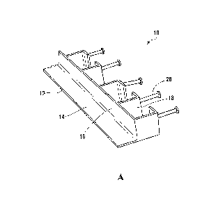
[0018] Figures 1 to 4 show an elongated straight embodiment of the
masonry support apparatus 10, and Figure 5 shows a 90 degree corner
embodiment of same. The masonry support apparatus 10 comprises a brick
support member 12, which has a horizontal section 14 and a vertical section 16
extending upwardly from a rear edge of the horizontal section 14. The length
of
the brick support member 12 can be varied, and for the example can be 10 feet
for the elongated straight piece embodiment, and can be 2 feet for each leg of
the 90 degree corner piece embodiment. The width of the brick support member
12 should be sufficient to fully support the typical 3 1/2 inch width of
veneer and
structural bricks, and for example can be 4 inches. The height of the brick
support member 12 can be varied, and for example can be 4 inches. A suitable
4
VAN_LAW\ 2508207 \ 1
CA 2987666 2017-12-01
material for the brick support member 12 is a 1/4" thick galvanized iron angle
bar;
however, other suitable materials known to one skilled in the art can be
substituted.
[0019] The masonry support apparatus 10 also comprises one or more
insulation brackets 18 attached to the rear of the brick support member 12,
and
longitudinally spaced along the length of the brick support member 12 to
matingly
receive insulation blocks. Each insulation bracket 18 comprises a pair of
longitudinally spaced angle members each comprising a lateral member 20 and a
longitudinal member 22 joined together to form a 90 degree angle. Each lateral
member 20 extends rearwardly from the vertical section 16 of the brick support
member 12. The lateral members 20 have a longitudinally spacing sufficient to
receive the length of an insulation block 24 there-between. Each longitudinal
member 22 extends longitudinally towards the other from the rear edge of each
lateral member 20, and terminates such that a longitudinal gap is defined. The
pair of angle members 20, 22 of each insulation bracket 18 define a generally
rectangular space that is sized to matingly receive the insulation block 24.
The
angle members 20, 22 can be made of the same material as the brick support
member 12, and for example, can be galvanized iron angle bars. The angle
members 20, 22 can be welded in a vertical orientation to the rear of the
vertical
section 18 of the brick support member 12.
[0020] As can be seen in Figures 1(b) and 2, a pair of adjacent
insulation
brackets 18 can be spaced from each other so that an insulation block 24 can
be
matingly fit in between the insulation brackets 18. The insulation blocks
typically
vary from 1" to 6" in thickness, and the size of the brackets 18 can be
adjusted
accordingly.
[0021] The masonry support apparatus 10 also comprises at least one
anchor for securing the apparatus 10 to a secure fixture in the building. In
the
illustrated embodiments, the masonry support apparatus 10 comprises multiple
5
VAN_LAW\ 2508207\1
CA 2987666 2017-12-01
concrete anchors 26, with each concrete anchor 26 extending rearwardly from
the longitudinal member 22 of each insulation bracket angle member. In some
embodiments, the concrete anchor 26 can be a Nelson stud welded to the back
side of the longitudinal member 22. The concrete anchors 26 are used to anchor
the masonry support apparatus 10 to a building floor, e.g. by being embedded
in
the concrete forming the floor.
[0022] The insulation brackets create a thermal break between a brick
wall
constructed on the brick support member 12 and a concrete floor, and the
insulation blocks 24 impede heat from escaping the building, whether by
radiation, convection, or conduction. However, heat can still be transmitted
relatively easily through the metal structure of the masonry support
apparatus. To
minimize conductive heat loss, the masonry support apparatus 10 can be
configured with a minimal cross section across the thermal break, and in
particular, the lateral members 20 of the insulation brackets 18 can comprise
relatively thin vertical plates. Further, the longitudinal members 22 of the
insulation brackets 18 can have a small surface area that minimizes contact
with
the concrete floor but which are still large enough to secure the insulation
blocks
in place.
[0023] Preferably, the brick support member 12, insulation bracket(s)
18
and concrete anchors 26 are permanently attached together, e.g. by welding, to
form a unitary structure. As will be described below, providing a unitary
structure
is expected to substantially simplify and quicken installation of the masonry
support apparatus 10, compared to prior art masonry support products, which
comprise separate components.
[0024] In use and referring to Figures 3, 4 and 6, multiple pieces of the
masonry support apparatus 10 can be arranged end to end to form a mold for the
concrete floor. The pieces of the masonry support apparatus 10 are positioned
so that the concrete anchors 26 extend into the mold. A first row of
insulation
6
VAN_LAVV\ 2508207\1
CA 2987666 2017-12-01
blocks 25 are then inserted into each insulation bracket 18 and in between
each
insulation bracket 18. Concrete is then poured into the mold until the
concrete
anchors 26 are covered and a concrete floor 25 is formed. Once the concrete
cures, the concrete anchors 26 are securely embedded into the concrete floor
25, and the insulation blocks 24 are securely in place. Then, rows of bricks
30
can be laid onto the brick support member 12 in the manner known in the art.
[0025] In contrast to prior art techniques, installing the masonry
support
apparatus 10 is quick and simple. Because the masonry support apparatus 10 is
a unitary structure, there is no need to perform multiple installation steps
of
setting support brackets, threading anchors, and mounting a support beam.
Furthermore, the unitary structure means that the masonry support apparatus 10
is always precisely aligned, such that brick and insulation blocks can be
easily
installed.
[0026] The terminology used herein is for the purpose of describing
particular embodiments only and is not intended to be limiting. Accordingly,
as
used herein, the singular forms "a", "an" and "the" are intended to include
the
plural forms as well, unless the context clearly indicates otherwise. It will
be
further understood that the terms "comprises" and "comprising," when used in
this specification, specify the presence of one or more stated features,
integers,
steps, operations, elements, and components, but do not preclude the presence
or addition of one or more other features, integers, steps, operations,
elements,
components, and groups. Directional terms such as "top", "bottom", "upwards",
"downwards", "vertically", and "laterally" are used in the following
description for
the purpose of providing relative reference only, and are not intended to
suggest
any limitations on how any article is to be positioned during use, or to be
mounted in an assembly or relative to an environment. Additionally, the term
"couple" and variants of it such as "coupled", "couples", and "coupling" as
used in
this description are intended to include indirect and direct connections
unless
7
VAN_LA1M 2508207\1
CA 2987666 2017-12-01
otherwise indicated. For example, if a first device is coupled to a second
device,
that coupling may be through a direct connection or through an indirect
connection via other devices and connections. Similarly, if the first device
is
communicatively coupled to the second device, communication may be through a
direct connection or through an indirect connection via other devices and
connections.
[0027] It is contemplated that any part of any aspect or embodiment
discussed in this specification can be implemented or combined with any part
of
any other aspect or embodiment discussed in this specification.
[0028] The scope of the claims should not be limited by the preferred
embodiments set forth in the examples, but should be given the broadest
interpretation consistent with the description as a whole.
8
VAN_LAVV\ 2508207\1
CA 2987666 2017-12-01