Note : Les descriptions sont présentées dans la langue officielle dans laquelle elles ont été soumises.
CA 02987830 2017-11-30
WO 2017/046627
PCT/IB2015/057039
AN ARRANGEMENT FOR MAINTAINING DESIRED TEMPERATURE
CONDITIONS IN AN ENCAPSULATED TRANSFORMER
FIELD
The present disclosure relates to the field of mechanical engineering. In
particular, the
present disclosure relates to encapsulated transformers.
BACKGROUND
Encapsulated or potted transformers are used in hazardous locations and harsh
industrial environments. An encapsulated transformer is a standard transformer
that is
encased in a potting material within a transformer enclosure. The potting
material is
generally a mixture of sand and resin. The product requirements of the
encapsulated
transformer state that the temperature rise within the wiring compartment of
the
transformer should typically not exceed 35 C and the enclosure temperature
rise should
typically not exceed 65 C. In order to achieve the above criteria, the
conventional
encapsulated transformers rely on potting material. More specifically, the
amount of
potting material used is increased to achieve a desired temperature gradient
within the
encapsulated transformer. The use of relatively larger quantity of potting
material
increases the cost and size of the encapsulated transformer.
Hence, in order to overcome the above mentioned drawbacks associated with the
conventional encapsulated transformers, there is need for an arrangement for
maintaining desired temperature conditions in an encapsulated transformer with
less
quantity of potting material, and consequently, making the transformer
relatively less
expensive and less bulky.
OBJECTS
Some of the objects of the present disclosure, which at least one embodiment
herein
satisfies, are as follows.
It is an object of the present disclosure to ameliorate one or more problems
of the prior
art or to at least provide a useful alternative.
1
An object of the present disclosure is to provide an arrangement for
maintaining desired
temperature conditions in an encapsulated transformer that is cost-effective.
Another object of the present disclosure is to provide an arrangement for
maintaining desired
temperature conditions in an encapsulated transformer that is not bulky and
does not require the
use of extra potting material
Other objects and advantages of the present disclosure will be more apparent
from the following
description, which is not intended to limit the scope of the present
disclosure.
SUMMARY
The present disclosure envisages an arrangement for maintaining desired
temperature conditions
on and within a transformer housing of an encapsulated transformer, the
arrangement
comprising: the transformer housing having a top wall, a bottom wall, and
sidewalls extending
between the top wall and the bottom wall; an insulation plate horizontally
disposed within the
housing, proximal to a transformer core and coil assembly of the encapsulated
transformer such
that the insulation plate is either partially or wholly embedded in a potting
material or abuts the
potting material, so as to contain the heat emanating from the transformer
core and coil
assembly; a metal plate extending horizontally from one of the sidewalls to an
oppositely
disposed sidewall of the sidewalls; the metal plate positioned above the
insulation plate forming
a first horizontally extending air gap between the metal plate and the
insulation plate; wherein a
wiring compartment is formed between the metal plate and the top wall of the
transformer
_________________________ housing, wherein the wiring compat intent is
positioned above the first horizontally extending air
gap; wherein a horizontally extending terminal plate is disposed within the
wiring compartment
between the metal plate and the top wall of the transformer housing thereby
forming a second
horizontally extending air gap between the metal plate and the terminal plate
and forming a third
horizontally extending air gap between the terminal plate and the top wall of
the transformer
housing; and wherein terminals of the encapsulated transformer are mounted on
the terminal
plate within the wiring compartment.
Typically, the material of the insulation plate is one of press-board sheet,
epoxy resin, bamboo,
paper, polymeric material, bakelite, ceramic, fabric, and a combination of
these materials. The
insulation plate may provide insulation against heat and/or electricity.
2
Date Recue/Date Received 2022-12-16
In an embodiment, the encapsulated transformer includes a plurality of
temperature sensors
disposed on and within the transformer housing.
Typically, the temperature sensors are thermocouples.
Preferably, the potting compound is a mixture of sand and a resin.
In an embodiment, the transformer housing comprises an operative upper chamber
and an
operative lower chamber, said operative lower chamber configured to house a
potted transformer
core and coil assembly, and said operative upper chamber configured to house
terminals
mounted on a terminal plate and wires extending from said transformer
2a
Date Recue/Date Received 2022-01-07
CA 02987830 2017-11-30
WO 2017/046627
PCT/1B2015/057039
core and coil assembly, and an insulation plate disposed at a location forming
a
junction between said upper chamber and said lower chamber, and being spaced
apart
from said terminal plate.
Typically, the terminal plate is of steel or aluminium or is a composite.
BRIEF DESCRIPTION OF ACCOMPANYING DRAWINGS
An arrangement for maintaining desired temperature conditions in an
encapsulated
transformer of the present disclosure will now be described with the help of
accompanying drawings, in which:
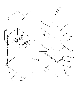
Fig. 1 illustrates exploded isometric views of an encapsulated transformer, in
accordance with the present disclosure;
Fig. 2 illustrates a sectional front view of the encapsulated transformer
having an
arrangement for maintaining desired temperature conditions within the
encapsulated
transformer, in accordance with an embodiment of the present disclosure; and
Fig. 3 illustrates a sectional side view of the encapsulated transformer of
Fig. 2.
DETAILED DESCRIPTION
The disclosure will now be described with reference to the accompanying
embodiments
which do not limit the scope and ambit of the disclosure. The description
provided is
purely by way of example and illustration.
The embodiments herein and the various features and advantageous details
thereof are
explained with reference to the non-limiting embodiments in the following
description.
Descriptions of well-known components and processing techniques are omitted so
as to
not unnecessarily obscure the embodiments herein. The examples used herein are
intended merely to facilitate an understanding of ways in which the
embodiments
herein may be practiced and to further enable those of skill in the art to
practice the
embodiments herein. Accordingly, the examples should not be construed as
limiting the
scope of the embodiments herein.
3
CA 02987830 2017-11-30
WO 2017/046627
PCT/IB2015/057039
The description of the specific embodiments will so fully reveal the general
nature of
the embodiments herein that others can, by applying current knowledge, readily
modify
and/or adapt for various applications such specific embodiments without
departing
from the generic concept, and, therefore, such adaptations and modifications
should and
are intended to be comprehended within the meaning and range of equivalents of
the
disclosed embodiments. It is to be understood that the phraseology or
terminology
employed herein is for the purpose of description and not of limitation.
Therefore,
while the embodiments herein have been described in terms of preferred
embodiments,
those skilled in the art will recognize that the embodiments herein can be
practiced with
modification within the spirit and scope of the embodiments as described
herein.
The product requirements of an encapsulated transformer state that the
temperature rise
in the wiring compartment of the encapsulated transformer should not exceed 35
C, and
the temperature rise on the walls of housing of the encapsulated transformer
should not
exceed 65 C. In order to achieve the desired temperature gradient, the
conventional
encapsulated transformers rely on the additional usage of the potting
compound, which
is generally epoxy resin. However, this results in an increased size of the
encapsulated
transformer. Furthermore, the additional usage of the potting compound also
has a
detrimental impact on the cost-effectiveness of the encapsulated transformer.
The present disclosure envisages an arrangement for maintaining desired
temperature
conditions in an encapsulated transformer. The use of the arrangement
disclosed in the
present disclosure results in a cost-effective product along with a reduced
size thereof.
Fig. 1 illustrates exploded isometric views of an encapsulated transformer
100. The
encapsulated transformer 100 is defined by a transformer housing 102. The
transformer
core and coil assembly 104 comprises a core 104A on which the primary windings
104B and secondary windings 104C are wound. In an assembled configuration, the
transformer core and coil assembly 104 is disposed within the transformer
housing 102
and a potting compound is poured therein to encapsulate the transformer core
and coil
assembly 104. In an embodiment, the potting compound is a mixture of resin and
sand.
In accordance with the present disclosure, insulation plates 106 are disposed
at various
locations proximal to the transformer core and coil assembly 104 within the
transformer
4
CA 02987830 2017-11-30
WO 2017/046627
PCT/1B2015/057039
housing 102 such that the insulation plates 106 are either partially or wholly
embedded
in the potting compound or abuts the potting compound, so as to contain the
heat
emanating from the transformer core and coil assembly 104.
In an embodiment, the transformer housing 102 comprises an operative upper
chamber
102A and an operative lower chamber 102B. The operative lower chamber 102B is
configured to house the potted transfoliner core and coil assembly 104, and
the
operative upper chamber 102A is configured to house terminals, mounted on a
terminal
plate 109, and wires extending from the transformer core and coil assembly
104. An
insulation plate 106 is disposed at a location forming a junction between the
operative
upper chamber 102A and the operative lower chamber 102B. A metal plate 108 is
disposed within the operative upper chamber 102A of the transformer housing
102 and
spaced apart from the insulation plate 106, which defines a wiring compartment
110 in
the operative upper chamber 102A of the transformer housing 102. The metal
plate 108
is of steel or aluminium or a composite thereof. The wiring compartment 110
houses
terminals of the encapsulate transformer 100 mounted on a terminal plate 109
(seen in
Fig. 3) and the wires extending from the transformer core and coil assembly
104 of the
encapsulated transformer 100.
Fig. 2 and Fig. 3 illustrate sectional views of the encapsulated transformer
100 having
an arrangement for maintaining desired temperature conditions within the
encapsulated
transformer (hereinafter referred to as arrangement 200), in accordance with
an
embodiment of the present disclosure. The arrangement 200 is now described
with
reference to Fig. 1, Fig. 2, and Fig. 3. The arrangement 200 comprises at
least one
insulation plate 106 that is disposed proximal to the transformer core and
coil assembly
104 such that the insulation plate 106 is either partially or wholly embedded
within the
potting compound 107 or abuts the potting compound 107. The insulation plate
106 is
adapted to substantially contain the heat emanating for the transformer core
and coil
assembly 104 during the course of operation thereof, thereby maintaining
desired
temperature conditions on and within the transformer housing 102. In an
embodiment,
the insulation plates 106 are insulation plates of a material selected from a
group
consisting of fiberglass, epoxy resin, bamboo, press-board paper, polymeric
material,
balcelite, ceramic, fabric, and a combination of these materials. For a press-
board paper
5
CA 02987830 2017-11-30
WO 2017/046627
PCT/1B2015/057039
insulation plate, the thickness ranges from 3mm to 13mm. In accordance with
the
present disclosure, the thermal conductivity of the insulation plate ranges
from 0.094 to
0.172 W/m/K.
In the embodiment, as seen in Fig. 2 and Fig.3, the arrangement 200 comprises
a top
insulation plate 106A disposed at a location forming a junction between the
operative
upper chamber 102A and the operative lower chamber 102B, a bottom insulation
plate
06B disposed operatively below the transformer core and coil assembly 104, a
front
insulation plate 106C, and side insulation plates 106D, 106E. The use of the
insulation
plates facilitates a substantial containment of the heat emanating from the
transformer
core and coil assembly 104 within the potting compound 107 and the insulation
plates.
Due to this additional insulation, a substantially reduced amount of heat is
transmitted
to the walls of the transformer housing 102. The result of this is a reduced
temperature
rise on the walls of the transformer housing 102, without the usage of the
additional
potting compound, as was the case with the conventional encapsulated
transformers.
The locations of the insulation plates in not limited to those disclosed in
Fig. 2 and Fig.
3. The insulation plates can be installed at various locations within the
transformer
housing 102 to maintain the desired temperature at various locations.
As explained previously, the metal plate 108 defines a wiring compartment 110
in the
operative upper chamber 102A of the transformer housing 102. The wiring
compartment 110 houses the terminals of the encapsulated transformer 100
mounted on
the terminal plate 109 and wires extending from the transformer core and coil
assembly
104. The product requirement of the encapsulated transformer state that the
temperature
rise within the wiring compartment 110 should not exceed 35 C. To this end,
the top
insulation plate 106A is disposed operatively above the transformer core and
coil
assembly 104. In an embodiment, the top insulation plate 106A is disposed such
that it
is submerged and encapsulated by the potting compound to ensure proper
placement
thereof. The metal plate 108, defining the wiring compartment 110, is disposed
in the
operative upper chamber 102A of the transformer housing 102, spaced apart from
the
top insulation plate 106A. As such, the heat emanated from the transformer
core and
coil assembly 104 is substantially contained by the potting compound and the
top
insulation plate 106A, and the heat being transmitted to the metal plate 108
is
6
CA 02987830 2017-11-30
WO 2017/046627
PCT/1B2015/057039
substantially reduced due to the effect of insulation plates as well as the
presence of air
gap between the insulation plate 106A and the metal plate 108. The result of
this being
that the temperature rise within the wiring compartment does not exceed 35 C.
The arrangement 200 further comprises a plurality of temperature sensors
112,..., 128.
The positions of the temperature sensors 112,..., 128 are illustrated in Fig.
1. The
temperature sensors 112,..., 128 facilitate the monitoring of the temperature
changes at
various locations on and within the transformer housing 102 of the
encapsulated
transformer 100. In an embodiment, the temperature sensors 112,..., 128 are
thermocouples. In another embodiment, the temperature sensors 112,..., 128 are
thermistors. The number of the temperature sensors 112,..., 128, as disclosed
in the
present embodiment, is nine. However, the number of the temperature sensors
112,...,
128 is not limited to nine, and can either be less than or greater than nine,
depending on
the application requirements.
In an experimental implementation, wherein the press-board paper insulation
plates
having thickness 9.525nam, and thermal conductivity 0.1625 W/m/K, were used,
the
temperature at different locations were measured via the temperature sensors
112,....,
128. The locations of the temperature sensors 112,...., 128 are seen in Fig.
1. Table 1
illustrates the values of the temperature obtained in the encapsulated
transformer 100
having the arrangement 200 compared with the temperature of the encapsulated
transformer without the arrangement 200.
TABLE 1
Temperature Temperature Rise in Temperature Rise in Temperature rise
sensor location the transformer the transformer with
Limit ( C)
without the use of the use of insulation
insulation plates( C) plates CC)
128 57 35 35
118 73 54 65
116 48 43 45
7
CA 02987830 2017-11-30
WO 2017/046627
PCT/1B2015/057039
Thus, it can be seen from the Table 1 that the arrangement 200 of the present
disclosure
facilitates the obtainment of the temperature conditions, at various locations
on the
transformer housing 102, which do not exceed the temperature limits specified
in the
product requirements of the encapsulated transformer.
Thus, the arrangement for maintaining desired temperature conditions in an
encapsulated transfoimer of the present disclosure facilitates a reduced usage
of the
potting compound in the encapsulated transformer by the use of the insulation
plates.
The reduced usage of the potting compound results in the reduced size of the
encapsulated transfoimer. Furthermore, the reduced usage of the potting
compound also
results in the reduced cost of the encapsulated transformer.
TECHNICAL ADVANCES AND ECONOMICAL SIGNIFICANCE
The arrangement for maintaining desired temperature conditions in an
encapsulated
transformer of the present disclosure described herein above has several
technical
advantages including, but not limited to, the realization of an arrangement
for
maintaining desired temperature conditions in an encapsulated transformer:
¨ such that the encapsulated transformer has reduced usage of the potting
material;
¨ such that the encapsulated transformer that has reduced size; and
¨ that is cost-effective.
Throughout this specification the word "comprise", or variations such as
"comprises"
or "comprising", will be understood to imply the inclusion of a stated
element, integer
or step, or group of elements, integers or steps, but not the exclusion of any
other
element, integer or step, or group of elements, integers or steps.
The use of the expression "at least" or "at least one" suggests the use of one
or more
elements or ingredients or quantities, as the use may be in the embodiment of
the
disclosure to achieve one or more of the desired objects or results.
Any discussion of documents, acts, materials, devices, articles or the like
that has been
included in this specification is solely for the purpose of providing a
context for the
disclosure. It is not to be taken as an admission that any or all of these
matters form a
8
CA 02987830 2017-11-30
WO 2017/046627
PCT/1B2015/057039
part of the prior art base or were common general knowledge in the field
relevant to the
disclosure as it existed anywhere before the priority date of this
application.
The numerical values mentioned for the various physical parameters, dimensions
or
quantities are only approximations and it is envisaged that the values
higher/lower than
the numerical values assigned to the parameters, dimcnsions or quantities fall
within
the scope of the disclosure, unless there is a statement in the specification
specific to
the contrary.
While considerable emphasis has been placed herein on the components and
component parts of the preferred embodiments, it will be appreciated that many
embodiments can be made and that many changes can be made in the preferred
embodiments without departing from the principles of the disclosure. These and
other
changes in the preferred embodiment as well as other embodiments of the
disclosure
will be apparent to those skilled in the art from the disclosure herein,
whereby it is to be
distinctly understood that the foregoing descriptive matter is to be
interpreted merely as
illustrative of the disclosure and not as a limitation.
9