Note : Les descriptions sont présentées dans la langue officielle dans laquelle elles ont été soumises.
CA 02991186 2018-01-02
WO 2017/001918 PCT/1B2016/001026
1
SINGLE USE DELIVERY DEVICE HAVING SAFETY FEATURES
Cross Reference to Related Applications
This application claims the benefit of and priority to U.S. Provisional
Application No.
62/188,108, filed July 2, 2015, the content of which is hereby incorporated by
reference herein in
its entirety.
Field of the Invention
The present invention generally relates to delivery devices for delivering
substances, such
as medicaments, and, more particularly, to a single use delivery device that
is rendered incapable
of reuse following receipt of a fluid agent from a source and subsequently
following its intended
use of delivering the fluid agent to a patient.
Background
Every year, millions of people become infected and die from a variety of
diseases, some
of which are treatable or entirely preventable. For example, many diseases may
be prevented via
immunization programs which include the administration of vaccines. Although
vaccination has
led to a dramatic decline in the number of cases of several infectious
diseases, some of these
diseases remain quite common. In many instances, large populations of the
world, particularly in
developing countries, suffer from the spread of vaccine-preventable diseases
due to ineffective
immunization programs, either because of poor implementation, lack of
affordable vaccines, or
inadequate devices for administering vaccines, or combinations thereof.
Some implementations of immunization programs generally include administration
of
vaccines via a typical reusable syringe. However, in many situations,
particularly in developing
countries, the administration of vaccines occur outside of a hospital and may
be provided by a
non-professional, such that injections are given to patients without carefully
controlling access to
syringes. The use of reusable syringes under those circumstances increases the
risk of infection
and spread of blood-borne diseases, particularly when syringes, which have
been previously used
and are no longer sterile, are used to administer subsequent injections. For
example, the World
Health Organization (WHO) estimates that blood-borne diseases, such as
Hepatitis and human
CA 02991186 2018-01-02
WO 2017/001918 PCT/1B2016/001026
2
immunodeficiency virus (HIV), are being transmitted due to reuse of such
syringes, resulting the
death of more than one million people each year.
Summary
The present invention provides a single use delivery device that overcomes the
drawbacks of current delivery devices and methods. In particular, the single
use delivery device
of the present invention is capable of delivering an agent (e.g., vaccine,
drug, medicament, etc.)
in a controlled manner and without requiring specialized skill in
administering delivery of such
agent. The delivery device is configured to be filled on-site and in the field
with a dose of a fluid
agent, while remaining sterile and preventing the potential for contamination
during the filling
process.
The delivery device includes numerous safety features for preventing the
potential for
reuse, thereby reducing the risk of the spreading blood-borne diseases through
reuse. For
example, a delivery device is configured to be coupled to a multi-dose source
of fluid agent (e.g.,
large volume syringe or other dispensing device containing multiple doses of a
fluid agent) so as
to be filled on-site and in the field with a dose of a fluid agent from the
multi-dose source. Upon
receiving an aliquot of fluid agent from the multi-dose source, the multi-dose
source and delivery
device may be separated from one another in a manner that renders refilling of
the delivery
device obsolete. In particular, the delivery device may include a safety
portion proximate to an
inlet port through which the fluid agent is to be received from the multi-dose
source. The safety
portion is configured to deform or separate from the delivery device upon
sufficient force applied
thereto as a result of disengagement between the multi-dose source and
delivery device. Upon
the safety portion deforming or entirely separating from the delivery device,
the inlet port of the
delivery device is rendered inoperable, such that additional fluid is unable
to be received within
the delivery device, thereby preventing the potential for reuse of the device
and allowing a single
one-time use. As such, the delivery device may be particularly useful in
situations in which
vaccines or drugs are being administered in non-healthcare related facilities
(e.g., outside of
clinics or hospitals) and given to large numbers of individuals over a short
period of time by a
non-professional.
In one aspect, the present invention provides a single use delivery device
including a base
member for delivering a fluid agent to a patient. The base member includes a
proximal end and
CA 02991186 2018-01-02
WO 2017/001918 PCT/1B2016/001026
3
a distal end. The base member further includes a channel having an inlet port
and an outlet port.
The inlet port is positioned at the proximal end and is configured to be
coupled to a source to
receive an aliquot of fluid agent therefrom. The outlet port is positioned at
the distal end and
configured to provide the aliquot of fluid agent to the patient. A portion of
the proximal end of
the base member adjacent to the inlet port is configured to render the inlet
port inoperable upon
disengagement of the source from the delivery device.
In some embodiments, the portion of the proximal end comprises a material
configured to
substantially deform upon sufficient application of force applied thereto as a
result of
disengagement of the source from the delivery device. In some embodiments, the
portion of the
proximal end is configured to become detached from the base member upon
sufficient
application of force applied thereto as a result of disengagement of the
source from the delivery
device. For example, the proximal end of the base member may include at least
one score line or
micro perforation pattern formed thereon and configured to allow the portion
of the proximal end
to tear or detach from the proximal end upon sufficient application of force
applied thereto. The
portion may include at least the inlet port, such that, upon separation of the
portion from the
proximal end, the inlet port is also separated from the base member, thereby
rendering the
delivery device incapable of receiving additional fluid.
By providing a breakaway or detachable proximal end, the delivery device is
configured
to be rendered incapable of reuse following receipt of a fluid agent from a
source, thereby
preventing reuse of the device and reducing the risk of the spreading blood-
borne diseases
through reuse. For example, the detachment or deformation of the proximal end
adjacent the
inlet port essentially prevents reconnection of the delivery device to a fluid
source, thereby
preventing additional fluid from being received within. Additionally, the
detachment or
deformation further provides visual indication that the device as already been
used, thus further
providing one more step of security and the prevention of attempted reuse of
the device.
Brief Description of the Drawings
FIG. 1 is a perspective exploded view of a single use delivery device
consistent with the
present disclosure.
FIG. 2 is a top elevation view of the single use delivery device of FIG. 1
illustrating the
base and top members in an assembled state.
CA 02991186 2018-01-02
WO 2017/001918 PCT/1B2016/001026
4
FIG. 3 is side view of the single use delivery device of FIG. 1 illustrating
the base and top
members in an assembled state.
FIG. 4 is a perspective view of a single use delivery device consistent with
the present
disclosure having multiple inlet ports.
FIGS. 5 and 6 illustrate coupling of the single use delivery device of FIG. 1
to a source
for providing a fluid agent to the single use delivery device.
FIG. 7 is a side view of a single use delivery device coupled to a multi-dose
source of
fluid agent illustrating a detachable portion of the delivery device.
FIGS. 8A and 8B illustrate different methods of separating the detachable
portion of
proximal end from the delivery device upon sufficient application of force
when disengaging the
multi-dose source from the delivery device.
FIG. 9 illustrates removal of the detachable portion of the proximal end from
the multi-
dose source.
FIGS. 10A and 10B illustrate other embodiments of a detachable proximal end of
the
delivery device and separation of proximal end upon sufficient application of
force when
disengaging the multi-dose source from the delivery device.
FIGS. 11A-11C are side views of the single use delivery device of FIG. 1
illustrating
different embodiments of needles to be used for intradermal, subcutaneous, and
intramuscular
delivery of a fluid agent, respectively.
FIG. 12 illustrates intradermal, subcutaneous, and intradermal delivery of a
fluid agent
with the single use delivery device of FIG. 1.
FIGS. 13A and 13B are perspective views of another embodiment of a needle
protector in
an open position, in which the penetrating tip of the needle is exposed, and a
closed position, in
which at least the penetrating tip of the needle is shielded and covered.
Detailed Description
The present invention provides a single use delivery device that is capable of
delivery an
agent (e.g., vaccine, drug, medicament, etc.) in a controlled manner and
without requiring
specialized skill in administering delivery of such agent. The delivery device
is configured to be
filled on-site and in the field with a dose of a fluid agent, while remaining
sterile and preventing
the potential for contamination during the filling process. The delivery
device is further
CA 02991186 2018-01-02
WO 2017/001918 PCT/1B2016/001026
configured to be rendered incapable of reuse following its receipt of a fluid
agent from a source
and subsequently following its intended use of delivering the fluid agent to a
patient, thereby
preventing reuse of the device and reducing the risk of the spreading blood-
borne diseases
through reuse.
By way of overview, the present invention provides a delivery device including
numerous safety features for preventing the potential for reuse, thereby
reducing the risk of the
spreading blood-borne diseases through reuse. For example, the delivery device
is configured to
be coupled to a multi-dose source of fluid agent (e.g., large volume syringe
or other dispensing
device containing multiple doses of a fluid agent) so as to be filled on-site
and in the field with a
dose of a fluid agent from the multi-dose source. Upon receiving an aliquot of
fluid agent from
the multi-dose source, the multi-dose source and delivery device may be
separated from one
another in a manner that renders refilling of the delivery device obsolete. In
particular, the
delivery device may include a safety portion proximate to an inlet port
through which the fluid
agent is to be received from the multi-dose source. The safety portion is
configured to deform or
separate from the delivery device upon sufficient force applied thereto as a
result of
disengagement between the multi-dose source and delivery device. Upon the
safety portion
deforming or entirely separating from the delivery device, the inlet port of
the delivery device is
rendered inoperable, such that additional fluid is unable to be received
within the delivery
device, thereby preventing the potential for reuse of the device and allowing
a single one-time
use. As such, the delivery device may be particularly useful in situations in
which vaccines or
drugs are being administered in non-healthcare related facilities (e.g.,
outside of clinics or
hospitals) and given to large numbers of individuals over a short period of
time by a non-
professional.
In one aspect, the present invention provides a single use delivery device
including a base
member for delivering a fluid agent to a patient. The base member includes a
proximal end and
a distal end. The base member further includes a channel having an inlet port
and an outlet port.
The inlet port is positioned at the proximal end and is configured to be
coupled to a source to
receive an aliquot of fluid agent therefrom. The outlet port is positioned at
the distal end and
configured to provide the aliquot of fluid agent to the patient. A portion of
the proximal end of
the base member adjacent to the inlet port is configured to render the inlet
port inoperable upon
disengagement of the source from the delivery device.
CA 02991186 2018-01-02
WO 2017/001918 PCT/1B2016/001026
6
In some embodiments, the portion of the proximal end comprises a material
configured to
substantially deform upon sufficient application of force applied thereto as a
result of
disengagement of the source from the delivery device. In some embodiments, the
portion of the
proximal end is configured to become detached from the base member upon
sufficient
application of force applied thereto as a result of disengagement of the
source from the delivery
device. For example, the proximal end of the base member may include at least
one score line or
micro perforation pattern formed thereon and configured to allow the portion
of the proximal end
to tear or detach from the proximal end upon sufficient application of force
applied thereto. The
portion may include at least the inlet port, such that, upon separation of the
portion from the
proximal end, the inlet port is also separated from the base member, thereby
rendering the
delivery device incapable of receiving additional fluid.
By providing a breakaway or detachable proximal end, the delivery device is
configured
to be rendered incapable of reuse following receipt of a fluid agent from a
source, thereby
preventing reuse of the device and reducing the risk of the spreading blood-
borne diseases
through reuse. For example, the detachment or deformation of the proximal end
adjacent the
inlet port essentially prevents reconnection of the delivery device to a fluid
source, thereby
preventing additional fluid from being received within. Additionally, the
detachment or
deformation further provides visual indication that the device as already been
used, thus further
providing one more step of security and the prevention of attempted reuse of
the device.
FIG. 1 is a perspective exploded view of a single use delivery device 10
consistent with
the present disclosure. FIGS. 2 and 3 are top and side elevation views of the
single use delivery
device 10 of FIG. 1 in an assembled state. As shown, the single use delivery
device 10 may
include a needle 11 having a tip configured for penetrating a target site and
injecting a fluid
agent into the target site. As will be described in greater detail herein, the
needle may include a
micro needle configured to penetrate a patient's skin down to a depth of the
dermis and deliver a
dosage of fluid agent thereto. In other embodiments, however, the needle 11
may be sized for
other injection types (e.g., intravenous, subcutaneous, intradermal, etc.). In
some embodiments,
the single use delivery device 10 of the present disclosure is not limited
solely to the
administration of a fluid agent via injection, and thus may be fitted with
other means of
delivering a fluid agent (e.g., nozzle tip, spray tip, droplet tip, etc.) in
lieu of a needle.
CA 02991186 2018-01-02
WO 2017/001918 PCT/1B2016/001026
7
The device 10 further includes a base member 12 and a top member 14 coupled
thereto,
wherein the combined base and top members 12, 14 are configured to provide the
fluid agent
into the needle for subsequent injection. As generally understood, the fluid
agent may include
any type of agent to be injected into a patient (e.g., mammal, either human or
non-human) and
capable of producing an effect. Accordingly, the agent may include, but is not
limited to, a
vaccine, a drug, a therapeutic agent, a medicament, or the like.
The base member 12 includes a proximal end 16 having an inlet port 18
configured to
receive fluid agent from a source and a distal end 20 having an outlet port 22
coupled to the
needle 11 and configured to provide the fluid agent thereto. As described in
greater detail herein,
the source of the fluid agent may include a filling syringe, for example,
configured to be
releasably coupled to the inlet port 18 of the base member 16. As shown, the
inlet port 18 may
include a Luer-type connection 19, such as a Luer-Lok fitting, configured to
releasably engage a
corresponding Luer-type connection on a hub of the syringe, thereby providing
a fluid
connection between the syringe and the inlet port 18 of the base member 12. It
should be noted
that the inlet port 18 need not be limited to an ISO standard (e.g. ISO 594)
luer fitting. In other
embodiments, the inlet port 18 may include non-standard connection fittings to
be coupled with
non-standard connection fitting of a source or adapter, for example.
Accordingly, by providing a
specialty connection fitting, only approved sources (e.g., multi-dose
dispensing devices) can be
used with the delivery devices of the present disclosure, thereby adding one
more layer of
security.
As shown, a seal member 21 may cover the inlet port 18 so as to prevent any
contaminants from entering the inlet port 18 and potentially contaminating the
delivery device 10
prior to filing the delivery device 10 with the fluid agent. For example, a
single use seal member
21 may be composed of a relatively thin sheet of material (e.g., metal foil,
plastic, etc.) may be
hermetically sealed to the opening of the inlet port 18, thereby preventing
contaminants (e.g.,
gases, fluids, dirt, debris, etc.) from entering the delivery device 10. The
seal member 21 may be
coupled to the inlet port 18 by any known sealing techniques (e.g., heat,
vibration, or adhesive
process). The seal member 21 is configured to be durable in the sense that it
provides a
sufficient seal with the inlet port 18 and prevent contaminants from entering
into the device 10
via the inlet port 18 while also being configured to be pliable and rupture
upon coupling of the
inlet port 18 to a source (e.g., hub of filler syringe), thereby allowing a
fluid to enter into the
CA 02991186 2018-01-02
WO 2017/001918 PCT/1B2016/001026
8
delivery device 10 via the inlet port 18. Accordingly, the seal member 21
provides a measure of
security to ensure that the delivery device 10 remains sterile until it is to
be used.
The base member 12 may further include a channel 24 formed within a portion
thereof
and providing a fluid pathway from the inlet port 18 to the outlet port 22.
Accordingly, upon
receipt of fluid agent from a source, via the inlet port 18, the fluid agent
may flow within the
pathway provided by the channel 24. The base member 12 further includes a one-
way valve 26
positioned within the fluid pathway of the channel 24. The one-way valve 26 is
configured to
permit antegrade flow of fluid from the inlet port 18 to the outlet port 22,
while preventing
retrograde flow (e.g., backflow) of fluid from the outlet port 22 through the
valve 26 and through
the inlet port 18. For example, the one-way valve 26 may include an open inlet
end and an
adjustable outlet end configured to move between a normally closed position
and an open
position. The one-way valve 26 is positioned such that the open inlet end is
configured to
receive fluid from the inlet port 18, and, upon sufficient application of
fluid pressure in a
direction away from the inlet port 18 and towards the outlet port 22 (e.g.,
depressing plunger of
filling syringe to fill device 10 with fluid agent) the outlet end of the
valve 26 moves from the
normally closed position to an open position to allow fluid to flow
therethrough in a direction
towards the outlet port 22, as indicated by the directional arrow. However,
when in a closed
position, the outlet provides a substantially leak-proof and/or airtight seal
so as to prevent any
fluid from entering the valve 26 from the outlet end. Furthermore, the valve
26 is configured
such that any application of fluid pressure in a direction away from the
outlet port 22 and
towards the outlet end of the valve 26, the outlet end remains closed, thereby
preventing any
fluid from flowing through the valve 26 in a retrograde direction from the
outlet port 22 towards
the inlet port 18. As generally understood, the one-way valve 26 may include
any type of valve
configured to permit fluid to flow only in a single direction. The one-way
valve 26 may include
any type of valve having medical grade material and configured to be used with
the flow of
fluids. For example, the one-way valve 26 may include a Reed valve or a
Heimlich valve.
The top member 14 may be formed separately from the base member 12, which
provides
advantages, as previously described herein. Accordingly, the top member 14 may
be coupled to
a portion of the base member 12 along a mounting section 28. For example, the
mounting
section 28 generally includes a large portion of the base member 12 and
includes at least a
portion of the channel 24 and the one-way valve 26, such that, upon coupling
the top member 14
CA 02991186 2018-01-02
WO 2017/001918 PCT/1B2016/001026
9
to the mounting section 28 of the base member 12, the top member substantially
encloses the
channel 24 and the one-way valve 26.
The top member 14 includes a compressible reservoir member 30 and a
compressible
valve cover 36, such that, upon coupling the top member 14 to the base member
12, the reservoir
member 30 is in fluid communication with the fluid pathway of the channel 24
and the valve
cover 36 substantially encloses the one-way valve 26. The top member 14 may
further include
an inlet 32 and an outlet 34 and defining a fluid pathway extending there
between and in fluid
communication with the reservoir member 30 and valve cover 36. Accordingly,
once coupled to
the base member 12, the inlet 34 and outlet 34 and the pathway extending there
between may
substantially correspond to the fluid pathway of the channel 24, thereby
cooperating with one
another to form a combined single channel pathway from the inlet port 18 to
the outlet port 22.
The top member 14 may be coupled to the base member 12 by any known means so
as to
create a hermetic seal. For example, the base and top members 12, 14 may be
sealed with one
another via any known adhesives, cements, ultrasonic welding, or thermoplastic
bonding
techniques. The base and top members 12, 14 are composed of a medical grade
material. In
some embodiments, the base member 12, the top member 14, or both, may be
composed of a
thermoplastic polymer, including, but not limited to, polypropylene,
polyethylene,
polybenzimidazole, acrylonitrile butadiene styrene (ABS) polystyrene,
polyvinyl chloride, PVC,
or the like.
The reservoir member 30 includes an interior volume configured to receive and
store a
fluid agent passing through the one-way valve 26. Upon applying a compression
force to the
reservoir member 30, the fluid agent is expelled into the fluid pathway of the
channel 24 and
through the outlet port 22 into the needle 11. Accordingly, the method of
delivering the fluid
agent into a patient is a relatively simple and straightforward process which
simply requires an
administrator to apply sufficient pressure to the filled reservoir member 30
so as to deform the
reservoir, resulting in expulsion of the stored fluid agent from the interior
volume. Due to the
one-way valve 26, the fluid agent is force to flow in a direction towards the
outlet port 22 and out
of the needle 11.
The base member 12 further includes a needle protector member 38 extending
from the
distal end 20 and adjacent to the outlet port 22. The needle protector member
38 may be coupled
to the distal end 20 by way of any known means. In the illustrated embodiment,
the needle
CA 02991186 2018-01-02
WO 2017/001918 PCT/1B2016/001026
protector member 38 is coupled to the distal end 20 by way of a living hinge
40, for example.
Accordingly, the needle protector member 38 is configured to move between a
closed position
and an open position, as indicated by arrow 42. When in a closed position, the
needle protector
member 38 is configured to substantially enclose the penetrating tip of the
needle 11, thereby
shielding one from inadvertent needle sticks. When in an open position, as
shown, the
penetrating tip of the needle 11 is exposed and ready for intradermal
injection on a target site of a
patient. Accordingly, the needle protector member 38 may be in a closed
position while the
delivery device 10 is being shipped, stored, and handled (e.g., during filling
of the delivery
device 10). An administrator need only move the needle protector member 38 to
an open
position to expose the needle 11 for delivering the fluid agent to a target
site on a patient. Upon
delivering the fluid agent, the administrator may then move the needle
protector member 38 to a
closed position and discard the delivery device 10, so as to prevent
unintentional needle sticks.
FIG. 4 is a perspective view of a single use delivery device 10 having
multiple inlet ports.
As shown, the proximal end 16 of the device 10 may include at least two inlet
ports 18a, 18b,
each configured to receive a separate fluid agent from a separate source, or,
in some instances,
the same fluid agent from the same source. As shown, each of the inlet ports
18a, 18b includes a
separate fluid pathway coupled to the one-way valve 26. Accordingly, the one-
way valve 26 is
configured to permit antegrade flow of first and second fluids from inlet
ports 18a, 18b,
respectively, in a direction towards the outlet port 22 and into the reservoir
member 30, while
preventing retrograde flow.
The multiple inlet ports 18a, 18b allow for two separate fluids to be loaded
into the
device 10 and subsequently mixed within the reservoir member 30. This may be
particularly
useful in situations in which a therapeutic agent or medicament is in
concentrated form and must
be diluted prior to administration to a patient. For example, inlet port 18a
may receive a fluid
concentrate and inlet port 18b may receive a diluent fluid (e.g., saline),
wherein the fluid
concentrate may be mixed with the diluent fluid within the reservoir member
30. Accordingly,
certain fluid agents or medicaments, such as certain vaccines, may be shipped,
or otherwise
stored, in a concentrated form and then diluted on-site when loading devices
10. The inclusion
of multiple ports 18a, 18b thus allows for administration of a multivalent
dose, which can be
loaded and mixed at the point of use.
CA 02991186 2018-01-02
WO 2017/001918 PCT/1B2016/001026
11
The inlet ports 18a, 18b may each include a connection fitting for coupling
the inlet port
18a, 18b to a source (e.g., filler syringe, other multi-dose dispensing
device, etc.) for dispensing
a specific fluid into the respective inlet port 18a, 18b, wherein the
connection fitting may be
associated with a specific fluid. For example, at least one of the inlet ports
may include a
standard Luer-type connection, such as a Luer-Lok fitting, associated with a
diluent fluid, while
the other inlet port may include a non-standard connection fitting associated
with a fluid
concentrate. For example, inlet port 18a may include a Luer-Lok fitting
configured to releasably
engage a corresponding Luer-type connection on a hub of a filler syringe to
thereby provide a
fluid connection between the syringe and the inlet port 18a. The standard Luer-
Lok fitting may
be associated with a filler syringe for dispensing saline, thus providing
visual indication to a user
that inlet port 18a is to be coupled to a saline source and receive saline
fluid within. The inlet
port 18b may include a non-standard connection fitting (e.g., a non-ISO
standard ISO 594 fitting)
which may have specific dimensions, geometry, and the like and configured to
fit with associated
connection fitting of a source containing the concentrated vaccine.
Accordingly, the non-
standard connection fitting allows for only a corresponding source to be
coupled thereto and
further provide visual indication to a user that the concentrated vaccine is
to be coupled to the
inlet port 18b.
The delivery device is configured to allow delivery of the agent to the
patient in a
relatively simple manner, without requiring specialized training for injecting
a needle portion
intradermally. In particular, the delivery device is designed such that it may
be filled on-site and
in the field with a microdose of an agent, while remaining sterile and
preventing the potential for
contamination during the filling process.
For example, FIGS. 5 and 6 illustrate coupling of the single use delivery
device 10 to a
multi-dose source for dispensing a fluid agent into the delivery device 10. In
the illustrated
embodiment, the source may include a filler syringe 100, for example. The
filler syringe 100
may be embodied as a conventional syringe. Accordingly, the filler syringe 100
includes a barrel
102 having a distal hub 104 configured to be releasably coupled to the inlet
port 18 of the base
member 12 of the delivery device 10. For example, the inlet port 18 may
include a Luer-type
connection 19, such as a Luer-Lok fitting, configured to releasably engage a
corresponding Luer-
type connection on the hub 104 of the syringe 100, thereby providing a fluid
connection between
CA 02991186 2018-01-02
WO 2017/001918 PCT/1B2016/001026
12
the interior volume of the barrel 102 of the syringe 100 and the inlet port 18
and subsequent fluid
pathway formed by the channel 24 of the base member 12.
In order to fill the delivery device 10, specifically the reservoir member 30,
with a fluid
agent 106 contained with the syringe 100, a person need only couple the hub
104 with the inlet
port 18. As shown in FIG. 5, the seal member 21 is intact and covering the
inlet port 18 so as to
prevent any contaminants from entering the inlet port 18 and potentially
contaminating the
delivery device 10 prior to filing the delivery device 10 with the fluid
agent. Upon inserting the
hub 104 into engagement with the inlet port 18, the hub 104 is configured to
pierce the seal
member 21, upon which the seal member 21 ruptures and tears, as indicated by
arrow 43, thereby
breaking the hermetic seal and allowing fluid to be providing from the syringe
100 into the
device 10 through the inlet port 18. For example, upon rotating either the
syringe 100 or device
10, as indicated by arrow 44, the hub 104 and inlet port 18 may contact and
come into threaded
engagement. A person may then fill the reservoir 40 with the fluid agent 106
by applying
pressure to a plunger 108 of the filler syringe 100, as indicated by arrow 46.
Due to the one-way
valve 26, the fluid agent 106 is only permitted to flow in a direction towards
the reservoir 30 and
prevented from flowing in a retrograde fashion out of the reservoir 30.
Furthermore, the interior
volume of the reservoir 30 may be within a range considered to be a micro
dose, such as 0.05 ml
to 1.0 ml. Accordingly, in some embodiments, the delivery device 10 does not
require exact
measurements when filling the reservoir 30. Instead, a person need only
completely fill the
reservoir, which includes the correct dosage, and, once completely filled, the
correct dosage has
been reached and the buildup of pressure will prevent the plunger 108 of the
syringe 100 from
advancing further. Accordingly, the device 10 allows consistent filling and
dosing of the fluid
agent 106 from device to device (e.g., filling up tens of hundreds of devices
10 at any one time).
Accordingly, when in the field or directly on-site, a person may use a single
filling syringe 100
to fill a plurality of empty delivery devices 10 in a consistent manner. The
filling syringe 100
essentially acts as a means of storing and dispensing aliquots of the fluid
agent.
As previously described, the delivery device 10 is configured to be rendered
incapable of
reuse following its receipt of a fluid agent from the source. In particular,
upon dispensing an
aliquot of fluid agent into the delivery device 10, a person may then
disengage the delivery
device 10 from the source 100 so as to render the delivery device 10 incapable
of subsequent
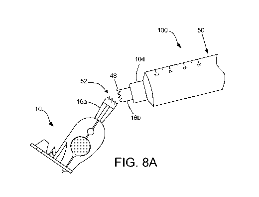
filling. For example, as shown in FIG. 7, the proximal end 16 of the delivery
device 10 may
CA 02991186 2018-01-02
WO 2017/001918 PCT/1B2016/001026
13
include a detachable portion, as indicated by dashed line 48. As shown in
FIGS. 8A and 8B, at
least a portion of the proximal end 16, including the inlet port 18, is
configured to separate from
the remainder of the delivery device 10 upon a force applied thereto when a
person attempts to
disengage the multi-dose source from the device.
The detachable portion of the proximal end 16 may include a material
configured to
substantially deform and/or tear upon sufficient application of force. In some
embodiments, the
proximal end 16 may include at least one score line or micro perforation
pattern 48 formed
thereon and configured to allow the portion of the proximal end 16 to tear or
detach from the
remainder of the proximal end 16 upon sufficient application of force applied
thereto. For
example, FIGS. 8A and 8B illustrate different methods of separating the
detachable portion of
proximal end 16 from the delivery device 10 upon sufficient application of
force when
disengaging the multi-dose source (e.g., syringe 100) from the delivery device
10. As shown in
FIG. 8A, while the syringe 100 remains coupled to the device 10, a person need
only apply
sufficient force against the syringe 100 (or alternatively against the device
10), as indicated by
arrow 50, such that the proximal end 16 splits into two portions along the
score line 48, as
indicated by arrow 52. In FIG. 8B, a user may need to only pull the device 10
and syringe 100
from one another in opposing directions, as indicated by arrows 54 and 56, in
order to split the
proximal end into two portions. In either case, first portion 16a of proximal
end remains with the
device 10 and a second portion 16b of proximal end, including the inlet port
18, remains coupled
to the syringe 100. As shown in FIG. 9, a user then need only rotate the
second portion 16b, as
indicated by arrow 58, so as to remove the second portion 16b from the hub 104
of the syringe
100, as indicated by arrow 60, so that the syringe 100 can be coupled to
another device to be
filled. It should be noted that, in some embodiments, most of the proximal end
16 may be
detachable. For example, as shown in FIGS. 10A and 10B, a majority of the
proximal end 16 is
detachable upon sufficient application of force applied thereto.
Upon detaching a portion of (or the entirety of) the proximal end 16, the
inlet port 18 is
also detached and separated from the device 10, thereby rendering the delivery
device 10
incapable of receiving additional fluid. As such, the delivery device may be
particularly useful
in situations in which vaccines or drugs are being administered in non-
healthcare related
facilities (e.g., outside of clinics or hospitals) and given to large numbers
of individuals over a
short period of time by a non-professional. By providing a breakaway or
detachable proximal
CA 02991186 2018-01-02
WO 2017/001918 PCT/1B2016/001026
14
end, the delivery device is configured to be rendered incapable of reuse
following receipt of a
fluid agent from a source, thereby preventing reuse of the device and reducing
the risk of the
spreading blood-borne diseases through reuse. For example, the detachment or
deformation of
the proximal end adjacent the inlet port essentially prevents reconnection of
the delivery device
to a fluid source, thereby preventing additional fluid from being received
within. Additionally,
the detachment or deformation further provides visual indication that the
device as already been
used, thus further providing one more step of security and the prevention of
attempted reuse of
the device.
Once filled, the delivery device 10 is designed such that a person
administering the agent
(e.g., administrator) may easily administer a dose of the fluid agent as
intended. For example,
FIGS. 11A-11C are side views of the single use delivery device 10 illustrating
different
embodiments of needles to be used for intradermal, subcutaneous, and
intramuscular delivery of
a fluid agent, respectively. FIG. 12 illustrates intradermal, subcutaneous,
and intradermal
delivery of a fluid agent with the single use delivery device 10.
The delivery device 10 is configured to allow delivery of the agent to the
patient in a
relatively simple manner, without requiring specialized training for injecting
a needle portion
intradermally. In particular, the delivery device is designed such that a
person administering the
agent (e.g., administrator) need only press the delivery device against the
administration site
(e.g., shoulder, arm, chest, etc.), in which the device is configured such
that needle penetration is
limited to the correct length and orientation within the administration site.
As shown, the
delivery device 10 may be removed from the filler syringe 100 and used to
administer the fluid
agent as a standalone device. However, it should be noted that the delivery
device 10 may
remain coupled to the filler syringe 100 during administration of the fluid
agent, such that an
administrator may use the filler syringe 100 as a handle or means of
stabilizing the delivery
device 10 during delivery of the fluid agent to a patient.
As shown in FIG. 11A, the needle 11 a is positioned substantially
perpendicular relative
to a plane along which the distal end 20 of the base member 12 lies, such that
the needle 11 a is
configured to be inserted into a patient's skin at a substantially
perpendicular angle. This is a
much more straightforward process for intradermal delivery of an agent,
particularly when
compared to the Mantoux procedure. Furthermore, the distal end is configured
to contact the
patient's skin during penetration of the needle 11a, thereby indicating
adequate depth of
CA 02991186 2018-01-02
WO 2017/001918 PCT/1B2016/001026
penetrating for intradermal injection of the fluid agent. For example, the
needle 11 a may be a
micro-needle having a length L1 (measured from the distal end 20) in the range
of 0.5 mm to 4
mm.
Other needles may be used with devices 10 of the present disclosure. For
example, as
shown in FIG. 11B, the device 10 may include a needle llb specifically
designed for
subcutaneous delivery of an agent. For example, the needle llb may have a
length L2 (measured
from the distal end 20) in the range of 8 mm to 15 mm. As shown in FIG. 11C,
the device 10
may include a needle llc specifically designed for intramuscular delivery of
an agent, such that
the llc has a length L3 (measured from the distal end 20) in the range of 18
mm to 30 mm.
Accordingly, as shown in FIG. 12, upon an administrator applying pressure in a
direction
towards the target site, as indicated by arrow 62, the needle 11 a is
configured to penetrate the
epidermis and dermis layers of skin. Needle llb is configured to penetrate the
epidermis, dermis
and subcutaneous layers. Needle llc is configured to penetrate the epidermis,
dermis,
subcutaneous, and muscle layers. Upon sufficient contact between the distal
end of the base
member 12 and the outer layer of skin, as indicated by arrow 64, the needles
11 a, 11b, llc have
achieved adequate penetration into the dermis for injection of the fluid agent
into the appropriate
layer. For example, upon the needle 11 a reaching the adequate depth into the
dermis, the
administrator may then compress the reservoir member 30 containing the dosage
of fluid agent
so as to deliver the fluid agent into the dermis. For example, the reservoir
member 30 is
configured to substantially collapse and reduce the interior volume upon
substantial compression
applied thereto, as indicated by arrow 66. An administrator need only fully
compress the
reservoir member 30 so as to expel to required dosage. Upon compression of the
reservoir
member 30, the fluid agent is expelled into the fluid pathway of the channel
24 and out of the
outlet port 22 and out of the needle 11, resulting in delivery of the fluid
agent into the dermis, as
indicated by arrow 68.
In some embodiments, the reservoir member 30 is shaped or sized such that,
upon
compression applied thereto, the reservoir member 30 is prevented from being
reformed and the
interior volume is prevented from expanding subsequent to substantial
compression.
Additionally, or alternatively, the valve cover 36 may be shaped or sized such
that, upon
compression applied thereto, the valve cover 36 is configured to substantially
collapse upon the
one-way valve 26 and render the one-way valve 26 inoperable, thereby blocking
fluid flow into
CA 02991186 2018-01-02
WO 2017/001918 PCT/1B2016/001026
16
or out of the one-way valve 26. Accordingly, the delivery device 10 configured
to be rendered
incapable of reuse following its delivery of the agent to a patient, thereby
preventing reuse of the
device and reducing the risk of the spreading blood-borne diseases through
reuse.
Accordingly, the delivery device 10 of the present invention does not require
a trained,
skilled healthcare profession for administration of vaccines or drugs. As
such, the delivery
device may be particularly useful in situations in which vaccines or drugs are
being administered
in non-healthcare related facilities (e.g., outside of clinics or hospitals)
and given to large
numbers of individuals over a short period of time by a non-professional.
It should further be noted that, in order to compensate for the variety of
different lengths
of needles 11 a-11 c, the device 10 may further include an alternative
embodiment of a needle
protector. FIGS. 13A and 13B are perspective views of a needle protector
member 70 in an open
position, in which the penetrating tip of the needle 11 is exposed, and a
closed position, in which
at least the penetrating tip of the needle 11 is shielded and covered by the
needle protector
member 70. Similar to needle protector member 38 previously described herein,
needle
protector member 70 generally extends from the distal end 20 of the device 10
and is adjacent to
the outlet port. The needle protector member 70 may be coupled to the distal
end 20 by way of
any known means. In the illustrated embodiment, the needle protector member 70
is coupled to
the distal end 20 by way of a living hinge, for example. Accordingly, the
needle protector
member 70 is configured to move between a closed position and an open
position. The needle
protector member 70 is shaped and/or sized so as to accommodate needles of a
specific length
(e.g., needles having a length between 0.5 and 30 mm or longer). For example,
when in a closed
position, as shown in FIG. 13B, the needle protector member 70 is configured
to substantially
enclose at least the penetrating tip of a needle 11, wherein the needle may
have a length between
4 mm and 30 mm or longer, such that the needle protector member 38 would be
inadequate and
would not accommodate a needle of such length. When in an open position, as
shown in FIG.
13A, the penetrating tip of the needle 11 is exposed and ready for intradermal
injection on a
target site of a patient.
The delivery device is configured to allow delivery of the agent to the
patient in a
relatively simple manner, without requiring specialized training for injecting
a needle portion
intradermally. In particular, the delivery device is designed such that it may
be filled on-site and
in the field with a microdose of an agent, while remaining sterile and
preventing the potential for
CA 02991186 2018-01-02
WO 2017/001918 PCT/1B2016/001026
17
contamination during the filling process. For example, when filling the
delivery device with a
fluid agent, a person need only couple a filler syringe containing the fluid
agent to the inlet port
and then fill the reservoir with the fluid agent by applying pressure to a
plunger of the filler
syringe. Due to the one-way valve, the fluid agent is only permitted to flow
within the reservoir
and prevented from flowing in a retrograde fashion out of the reservoir.
Furthermore, the
interior volume of the reservoir may be within a range considered to be a
micro dose. Thus, the
delivery device does not require exact measurements when filling the
reservoir. Instead, a
person need only completely fill the reservoir, which includes the correct
dosage, and further
prevents overfilling, as the interior volume is limited to the dosage amount
for any given fluid
agent.
Because the delivery device itself is not prefilled, the delivery device of
the present
invention does not require the maintenance of a certain temperature (e.g., 2
to 8 degrees Celsius)
during shipment or storage, thus cutting down on the overall costs. Rather
than maintaining the
delivery device at a constant temperature, as is the case with current
devices, only the source
containing the vaccine or drug (e.g., single supply provided in filling
syringe) need by
maintained at a constant temperature. Additionally, because the delivery
device is configured to
store and deliver a microdose of agent, the delivery device allows for dose-
sparing. Dose-
sparing may provide for a successful immunization program, particularly in
resource-poor
settings, by potentially reducing the per-injection cost (including transport
and storage) of
vaccines because more doses might be obtained from the existing vaccine
presentation. Dose-
sparing might also extend the availability of vaccines in cases where supply
is limited by
manufacturing capacity. Accordingly, a plurality of empty delivery devices may
be shipped and
stored, at a reduced cost, and then filled directly on-site and on an as-
needed basis, such that only
a single filler syringe is required for hundreds of doses to be delivered at
any given point.
Once filled, the delivery device is designed such that a person administering
the agent
(e.g., administrator) need only press the delivery device against the
administration site (e.g.,
shoulder, arm, chest, etc.), in which the device is configured such that
needle penetration is
limited to the correct length and orientation within the administration site.
For example, in some
embodiments, the needle is positioned substantially perpendicular relative to
a plane along which
the distal end of the base member lies, such that the needle is configured to
be inserted into a
CA 02991186 2018-01-02
WO 2017/001918 PCT/1B2016/001026
18
patient's skin at a substantially perpendicular angle and the distal end is
configured to contact the
patient's skin indicating adequate depth of penetrating for intradermal
injection of the fluid agent.
Upon needle penetration, the administrator then may fully compress a reservoir
containing the micro dose of agent, thereby delivering the correct predefined
dosage to the
patient. The delivery device is further configured to be rendered incapable of
reuse following its
delivery of the agent to a patient, thereby preventing reuse of the device and
reducing the risk of
the spreading blood-borne diseases through reuse. For example, in some
embodiments, the
reservoir member is configured to substantially collapse and reduce the
interior volume upon
substantial compression applied thereto. In particular, the top member may
include an inelastic
material such that the reservoir member is prevented from being reformed and
the interior
volume prevented from expanding subsequent to substantial compression. In some
embodiments, the top member may further include a valve cover configured to
substantially
enclose the one-way valve within. Upon substantial compression applied to the
valve cover, the
valve cover is configured to substantially collapse upon the one-way valve and
render the one-
way valve inoperable, thereby blocking fluid flow from the inlet port to the
reservoir member.
Furthermore, the delivery device may be configured to prevent unintentional
needle
sticks, and thus reduce the potential for spreading blood-borne diseases. For
example, in some
embodiments, the base member further includes a needle protector member
extending from distal
end adjacent to the outlet port. The needle protector member is configured to
move between a
closed position, in which a penetrating tip of the needle is shielded, and an
open position, in
which the penetrating tip of the needle is exposed.
While several embodiments of the present disclosure have been described and
illustrated
herein, those of ordinary skill in the art will readily envision a variety of
other means and/or
structures for performing the functions and/or obtaining the results and/or
one or more of the
advantages described herein, and each of such variations and/or modifications
is deemed to be
within the scope of the present disclosure. More generally, those skilled in
the art will readily
appreciate that all parameters, dimensions, materials, and configurations
described herein are
meant to be exemplary and that the actual parameters, dimensions, materials,
and/or
configurations will depend upon the specific application or applications for
which the teachings
of the present disclosure is/are used.
CA 02991186 2018-01-02
WO 2017/001918 PCT/1B2016/001026
19
Those skilled in the art will recognize, or be able to ascertain using no more
than routine
experimentation, many equivalents to the specific embodiments of the
disclosure described
herein. It is, therefore, to be understood that the foregoing embodiments are
presented by way of
example only and that, within the scope of the appended claims and equivalents
thereto, the
disclosure may be practiced otherwise than as specifically described and
claimed. The present
disclosure is directed to each individual feature, system, article, material,
kit, and/or method
described herein. In addition, any combination of two or more such features,
systems, articles,
materials, kits, and/or methods, if such features, systems, articles,
materials, kits, and/or methods
are not mutually inconsistent, is included within the scope of the present
disclosure.
All definitions, as defined and used herein, should be understood to control
over
dictionary definitions, definitions in documents incorporated by reference,
and/or ordinary
meanings of the defined terms.
The indefinite articles "a" and "an," as used herein in the specification and
in the claims,
unless clearly indicated to the contrary, should be understood to mean "at
least one."
The phrase "and/or," as used herein in the specification and in the claims,
should be
understood to mean "either or both" of the elements so conjoined, i.e.,
elements that are
conjunctively present in some cases and disjunctively present in other cases.
Other elements
may optionally be present other than the elements specifically identified by
the "and/or" clause,
whether related or unrelated to those elements specifically identified, unless
clearly indicated to
the contrary.
Reference throughout this specification to "one embodiment" or "an embodiment"
means
that a particular feature, structure, or characteristic described in
connection with the embodiment
is included in at least one embodiment. Thus, appearances of the phrases "in
one embodiment"
or "in an embodiment" in various places throughout this specification are not
necessarily all
referring to the same embodiment. Furthermore, the particular features,
structures, or
characteristics may be combined in any suitable manner in one or more
embodiments.
The terms and expressions which have been employed herein are used as terms of
description and not of limitation, and there is no intention, in the use of
such terms and
expressions, of excluding any equivalents of the features shown and described
(or portions
thereof), and it is recognized that various modifications are possible within
the scope of the
claims. Accordingly, the claims are intended to cover all such equivalents.
CA 02991186 2018-01-02
WO 2017/001918 PCT/1B2016/001026
Incorporation by Reference
References and citations to other documents, such as patents, patent
applications, patent
publications, journals, books, papers, web contents, have been made throughout
this disclosure.
All such documents are hereby incorporated herein by reference in their
entirety for all purposes.
Equivalents
Various modifications of the invention and many further embodiments thereof,
in
addition to those shown and described herein, will become apparent to those
skilled in the art
from the full contents of this document, including references to the
scientific and patent literature
cited herein. The subject matter herein contains important information,
exemplification and
guidance that can be adapted to the practice of this invention in its various
embodiments and
equivalents thereof.