Note : Les descriptions sont présentées dans la langue officielle dans laquelle elles ont été soumises.
CUTTING IMPLEMENT FOR HAMMER TACKER
Field of Invention
This invention relates generally to a hammer tacker, and, more specifically,
to
a cutting implement adapted to be used with a conventional hammer tacker.
Background of the Invention
A conventional hammer tacker is used for driving staples into a work piece.
Generally, a hammer tacker comprises a body and a staple magazine attached to
the
body for holding the staples. Hammer tackers may also include a handle for
gripping
same such that a "hammering" action dispenses the staples, as opposed to
squeezing a
lever, as is the case for lever-operated staplers. Hammer tackers are commonly
used
to tack down construction materials such as insulating materials, sheet
materials,
roofing paper and the like. An example of a typical hammer tacker is shown in
U.S.
7,537,147.
Often the construction materials, in particular, when being attached to
corners
and the like, require cutting to fit in the particular space. Conventional
utility knives
are usually used for cutting the material. However, use of such conventional
knives
require the tacker operator to put down the tacker and pick up the knife for
cutting.
Hammer tackers having a cutter positioned on the opposite end from where the
staples
are dispensed are known in it art (see, for example, U.S. Patent No. 5,911,761
and
U.S. Publication No. 2006/0253996). However, the disadvantage of these hammer
tackers is that the hammer tacker must be rotated in order to access the
cutting
portion, which may result in dropping the tacker.
U.S. Patent No. 6,823,592 discloses a hammer tacker having a cutter attached
to the top of a conventional hammer tacker. However, the blade is positioned
on a
side extension and therefore projects at an angle relative to the tacker body.
Because
of such side extension, it may cover the field of visibility during operation
and may
1
WSLEGAL\067847\00008\19118889vI
CA 2992189 2018-01-17
prevent the operator from operating the hammer tacker in an inside corner,
around
windows and doors, etc.
Summary of Invention
The present invention provides a cutting implement for use with a
conventional hammer tacker and a hammer tacker having such a cutting
implement.
In one aspect, a cutting implement is provided for attaching to a hammer
tacker,
comprising:
= an elongated plate for attaching to an elongated top surface of the
hammer
tacker;
= a pair of side walls extending upwardly from each side of the elongated
plate,
said side walls forming a slot for receiving a cutting blade; and
= an actuator for moving the cutting blade from a retracted position to an
extended position through the slot such that when the cutting blade is in the
extended position, a portion of the cutting blade extends past a front end of
the
hammer tacker without significantly obscuring a side to side sight line of the
hammer tacker;
whereby the elongated plate is sized and shaped such that when the elongated
plate is
attached to the elongated top surface it does not substantially increase the
side to side
dimensions of the hammer tacker.
In one embodiment, the elongated plate is attached to the elongated top
surface by means of a fastener. Examples of fasteners useful for attaching the
elongated plate to the elongated top surface of the hammer tacker are screws,
bolts,
nails, nuts, pins, clips, rivets, rods, and other such anchors. In another
embodiment,
the elongated plate is attached to the elongated top surface of the hammer
tacker by
means of glue such as epoxy glue, cyanoacrylate adhesives, and the like. In
another
embodiment, the elongated plate is attached to the elongated top surface of
the
hammer tacker by welding, brazing, soldering, and the like.
2
WSLEGAL\067847\00008\ 19 I I 8889v1
CA 2992189 2018-01-17
In one embodiment, the side walls have inwardly overturned side edges to
hold the cutting blade securely.
In another aspect, a hammer tacker and cutting apparatus is provided,
comprising:
= a hammer tacker having a substantially level elongated top surface;
= an elongated
plate for attaching to the elongated top surface of the hammer
tacker;
= a pair of side walls extending upwardly from each side of the elongated
plate,
said side walls forming a slot for receiving a cutting blade; and
= an actuator for moving the cutting blade from a retracted position to an
extended position through the slot such that when the cutting blade is in the
extended position, a portion of the cutting blade extends past a front end of
the
hammer tacker without significantly obscuring a side to side sight line of the
hammer tacker;
whereby the elongated plate is sized and shaped such that when the elongated
plate is
attached to the elongated top surface it does not substantially increase the
side to side
dimensions of the hammer tacker.
Brief Description of the Drawings
Drawings are included for the purpose of illustrating certain aspects of the
invention. Such drawings and the description thereof are intended to
facilitate
understanding and should not be considered limiting of the invention. Drawings
are
included, in which:
Fig. 1 is a perspective view of an elongated plate of a cutting implement of
the
present invention.
Fig. 2 is a perspective view and partial cut-away of the elongated plate shown
in Fig. 1.
3
WSLEGAL\067847\00008\19118889v1
CA 2992189 2018-01-17
Fig. 3 is a perspective view of an embodiment of an actuator useful in a
cutting implement of the present invention.
Fig. 4 is a perspective view of a blade useful in a cutting implement of the
present invention.
Fig. 5 is a perspective view of a hammer tacker having a cutting implement of
the present invention attached thereto.
Figs. 6A and 6B are top views of the hammer tacker as shown in Fig. 5 when
the cutting blade is extended and retracted, respectively.
Figs. 7A (Prior Art), 7B (Prior Art) and Fig. 7C (Prior Art) are top view,
cross
section and perspective view, respectively, of a hammer tacker useful in the
present
invention.
Figs. 8A, 8B and 8C are top view, cross section and perspective view,
respectively, of a hammer tacker having a cutting implement of the present
invention
attached thereto.
Detailed Description of Various Embodiments
The detailed description set forth below in connection with the appended
drawings is intended as a description of various embodiments of the present
invention
and is not intended to represent the only embodiments contemplated by the
inventor.
The detailed description includes specific details for the purpose of
providing a
comprehensive understanding of the present invention. However, it will be
apparent
to those skilled in the art that the present invention may be practiced
without these
specific details.
The various components of one embodiment of a cutting implement of the
present invention are shown in Figs. 1-4. In this embodiment, the cutting
implement
comprises an elongated plate (3) having two side plates (2), each side plate
having
overturned edges (12) forming a slot (14) for receiving a cutting blade (4),
and
actuator (11) shown in Fig. 4 and Fig. 3, respectively. At one end of
elongated plate
4
WSL,EGAI W67847\00008\ 19118889v I
CA 2992189 2018-01-17
(3) is a raised hemi-spherical knob (7) and at the opposite end of the
elongated plate
(3), the plate is bent first upwardly and then downwardly to form a lip (8).
Fig. 2 is a
partial cut-away of Fig. 1, which shows the contour of lip (8). The lip (8)
aids in
stabilizing blade (4), as will be described in more detail below. Elongate
plate (3)
further comprises a plurality of additional, raised smaller knobs (6), which
profiles
can be seen in Fig. 2.
Actuator (11), as shown in Fig. 3, is useful for both securing cutting blade
(4)
and for moving cutting blade (4) forwards and backwards through slot (14).
Actuator
(11) comprises a cutting blade fastener (9) at first end (13), which fastener
(9) can be
inserted in aperture (9a) of cutting blade (4) to secure the cutting blade (4)
to the
actuator (11). Actuator (11) further comprises a dial (5) which can move the
blade (4)
either forwards and backwards, to extend or retract the blade (4). Second end
(15)
comprises a v-shaped depression (10) which stops the blade (4) from extending
too
far forward by allowing the depression (10) to rest in between two adjacent
smaller
knobs (6).
As shown in Fig. 4, blade (4) can be formed of a plurality of segments (4a)
such that when the tip of the blade (4) gets dull, the spent segment of blade
(4) can be
broken off and a new segment of the blade (4) can now be exposed for use.
Actuator (11), and blade (4) attached thereto, is sized to freely slide back
and
forth in slot (14) formed by plates (2) and the overturned edges (12) serve to
retain the
actuator (11) and blade (4) while still allowing the actuator and blade to
move
forwards and backwards to extend or retract blade (4). It is understood that
other
actuators that can move a cutting blade forwards and backwards could also be
used in
the present invention. When blade (4) is moved forward past the raised lip (8)
of
elongated plate (2), the raised lip (8) helps fix the blade in position so
that the blade is
secure enough to cut the building material.
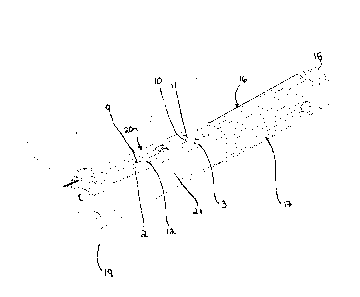
Fig. 5 is a perspective view of the assembled cutting implement (20) of the
present invention attached to a conventional hammer tacker. An example of a
hammer tacker useful in the present invention is described in U.S. Patent No.
5
WS L EGAL\067847\00008\19118889v1
CA 2992189 2018-01-17
7,537,147, incorporated hereto by reference. In Fig. 5, hammer tacker (16)
comprises
a hand grip (17) at one end, which grip can be made of a non-slip material
such as
rubber, or can be made of steel, etc. and wrapped with rubber, etc., to
provide a
stronger grip. At the end of the hand grip (17) is a staple magazine (18),
which can be
inserted into the hand grip by means known in the art. At the other end of
hammer
tacker (16) is an elongated top surface (22) at or near the stapling portion
(21)
comprising stapling head (19), which operation is known in the art.
Cutting implement (20) is fixed to the elongated top surface (22) of the
hammer tacker (16) by any means known in the art, such as gluing, welding,
screwing, etc. To allow the cutting implement (20) to be fixed to the
elongated top
surface (22), as well as to improve the aesthetics of the tool, certain
structural changes
may need to be made to an existing hammer tacker tool.
In one embodiment of a hammer tacker useful in the present invention, which
is shown in Figs. 7A, 7B and 7C (Prior Art), the hammer tacker (216) comprises
an
overturned lip (224) at the front of the stapling portion (219). Screw (231a)
secures
lip (224) to the elongated tope surface (222) of the tacker hammer (216). As
well,
screw 231a, together with screw 231b, secures weight (226), which weight can
be
made of a heavy metal such as steel, for exerting more force on the stapling
portion
(221) of the tacker hammer (216) for embedding the staples in a material.
Thus,
screws (231a, 231b) must be removed to provide a substantially level elongated
top
surface (222). Once the lip (224) and screws (231a, 231b) are removed, the
elongated
top surface (222) will be flat and will allow for the installation of the
cutting
implement (220), as shown in Fig. 7C.
As shown in Figs. 8A, 8B and 8C, two countersunk screws (235a, 235b) can
now be used to both fixing the weight (226) and the cutting implement (220) in
place.
First, the weight can be fixed into place with countersunk screws, the head of
which
goes completely into the plane of the elongated top surface (222) and leaves a
flat
surface.
6
WSLEGAL\067847\00008\ I 9118889v1
CA 2992189 2018-01-17
In another embodiment, instead of using any screws, two holes can be drilled
into the sides of the stapling portion of a tacker hammer the weight can be
welded to
the body of the stapling portion through these holes. In another embodiment,
spot-
welding can be used in two spots on each of the sides of the body of the
stapling
portion, or on the top, or in other places. The spot-welding requires a very
exact fit of
the weight with the inner structure of the body of the stapling portion.
In one embodiment, hammer tacker (16) may further comprise a pair of small,
upright wing members (1) attached to the top of the stapling head (19) which
provide
protection to the blade (4) in case the user hits anything with the top of the
stapling
head; this may occur by accident or may be done intentionally. If the upright
wing
members (1) were not present and the user inadvertently struck any object,
such as a
wall, with the top of the stapling head (19) a segment of the blade (4) may
break off
or, what would be worse, the overturned edges (12) may get bent, warped or
damaged
and have a severe impairment on the functionality of the cutting implement
(20).
As can be seen more clearly in the top views in Figs. 6A and 6B, when cutting
implement (20) is attached to the hammer tacker (16), and, in particular, when
the
cutting blade is in the retracted position as shown in Fig. 6B, the cutting
implement
(20) does not substantially cover the field of visibility of the user of the
hammer
tacker and it still allows the operator to use the hammer tacker in an inside
corner,
around windows and doors, etc. However, when cutting of materials is
necessary, the
user can easily extend the cutting blade (4) forward to engage in the cutting
operation.
Further, because the cutting blade (4) only extends from the front of the
hammer
tacker (Fig. 6A), it is much safer for the user and there is less chance of
the user
injuring himself during cutting operations. Further, because the cutting blade
(4) can
be flipped in either direction when loading into the cutting implement, both a
left-
handed and a right-handed user can use it with equal comfort and skill.
Additionally,
because the cutting blade is positioned on its side, with the sharp cutting
edge on
either the left side (for right-handed users) or the right side (for left-
handed users)
should the user accidentally hit him or herself with the cutting blade then
the cutting
blade will not injure the user.
7
W S L EGA L \ 067847 \ 00008 \19118889v1
CA 2992189 2018-01-17
The previous description of the disclosed embodiments is provided to enable
any person skilled in the art to make or use the present invention. Various
modifications to those embodiments will be readily apparent to those skilled
in the art,
and the generic principles defined herein may be applied to other embodiments
without departing from the spirit or scope of the invention. Thus, the present
invention is not intended to be limited to the embodiments shown herein, but
is to be
accorded the full scope consistent with the claims, wherein reference to an
element in
the singular, such as by use of the article "a" or "an" is not intended to
mean "one and
only one" unless specifically so stated, but rather "one or more". All
structural and
functional equivalents to the elements of the various embodiments described
throughout the disclosure that are known or later come to be known to those of
ordinary skill in the art are intended to be encompassed by the elements of
the claims.
Moreover, nothing disclosed herein is intended to be dedicated to the public
regardless of whether such disclosure is explicitly recited in the claims. For
US
patent properties, it is noted that no claim element is to be construed under
the
provisions of 35 USC 112, sixth paragraph, unless the element is expressly
recited
using the phrase "means for" or "step for".
25
8
WSLEGAL\067847 \00008 1 19118889v1
CA 2992189 2018-01-17