Note : Les descriptions sont présentées dans la langue officielle dans laquelle elles ont été soumises.
05002993-2097CA
96664
SYSTEM AND METHOD FOR SELECTING AN OPENING ANGLE OF AN
AUXILIARY POWER UNIT INLET DOOR
CROSS-REFERENCE TO RELATED APPLICATIONS
[0001] This patent application claims priority under 35 USC 119(e) of US
provisional Application Serial No. 62/461057, filed on February 20, 2017, the
contents of which are hereby incorporated by reference.
TECHNICAL FIELD
[0002] The application relates generally to auxiliary power units and, more
particularly, to controlling an opening angle of an auxiliary power unit inlet
door.
BACKGROUND OF THE ART
[0003] An auxiliary power unit (APU) may be provided with an inlet door that
is
moveable between a closed position and one or more open positions to allow
airflow
into the APU and accordingly provide the desired APU functionalities.
[0004] In some existing systems, the APU inlet door is typically commanded
fully
open when the aircraft is on the ground and commanded partially open at all
times
when the aircraft is in flight. This approach is however not optimal for high
altitude
load applications. There is therefore a need for an improved system and method
for
controlling an auxiliary power unit inlet door.
SUMMARY
[0005] In one aspect, there is provided a method for controlling an inlet door
of an
auxiliary power unit provided on an aircraft. The method comprises receiving
input
data indicative of whether the aircraft is on ground or airborne, if the
aircraft is on
ground, outputting a first control signal comprising instructions to command
the inlet
door to a fully open position, and, if the aircraft is airborne, outputting a
second
control signal comprising instructions to command the inlet door to a
partially open
position and then outputting a third control signal comprising instructions to
transition the inlet door from the partially open position to the fully open
position
when a current value of a rotational speed of the auxiliary power unit reaches
a
1
CA 2993579 2018-01-30
05002993-2097CA
96664
predetermined threshold indicative of an end of a start sequence of the
auxiliary
power unit.
[0006] In another aspect, there is provided a system for controlling an inlet
door of
an auxiliary power unit provided on an aircraft. The system comprises a memory
and a processing unit coupled to the memory and configured to receive input
data
indicative of whether the aircraft is on ground or airborne, if the aircraft
is on ground,
output a first control signal comprising instructions to command the inlet
door to a
fully open position, and, if the aircraft is airborne, output a second control
signal
comprising instructions to command the inlet door to a partially open position
and
then output a third control signal comprising instructions to transition the
inlet door
from the partially open position to the fully open position when a current
value of a
rotational speed of the auxiliary power unit reaches a predetermined threshold
indicative of an end of a start sequence of the auxiliary power unit.
[0007] In a further aspect, there is provided a computer readable medium
having
stored thereon program code executable by a processor for receiving input data
indicative of whether the aircraft is on ground or airborne, if the aircraft
is on ground,
outputting a first control signal comprising instructions to command an inlet
door of
an auxiliary power unit provided on an aircraft to a fully open position, and,
if the
aircraft is airborne, outputting a second control signal comprising
instructions to
command the inlet door to a partially open position and then outputting a
third
control signal comprising instructions to transition the inlet door from the
partially
open position to the fully open position when a current value of a rotational
speed of
the auxiliary power unit reaches a predetermined threshold indicative of an
end of a
start sequence of the auxiliary power unit.
DESCRIPTION OF THE DRAWINGS
[0008] Reference is now made to the accompanying figures in which:
[0009] Figure 1 is a schematic representation of an aircraft including an APU;
in
accordance with an illustrative embodiment;
[0010] Figure 2 is a block diagram of a system for controlling an inlet door
of the
APU of Figure 1, in accordance with an illustrative embodiment;
2
CA 2993579 2018-01-30
05002993-2097CA
' 96664
[0011] Figure 3 is a block diagram of a computing device for implementing the
electronic engine controller of Figure 2, in accordance with an illustrative
embodiment;
[0012] Figure 4 is a flowchart of a method for controlling an inlet door of
the APU of
Figure 1, in accordance with an illustrative embodiment; and
[0013] Figure 5 is a flowchart of a method for controlling an inlet door of
the APU of
Figure 1, in accordance with another illustrative embodiment.
DETAILED DESCRIPTION
[0014] Referring to Figure 1, in one embodiment, an aircraft 10 has mounted
thereon an APU 12, which is provided for conventional purposes, including, but
not
limited to, the provision of electrical power 14 and pneumatic air 16 to the
aircraft 10.
Among other well-known uses, pneumatic air 16 provided by the APU 12 is used
on
larger aircraft to provide auxiliary bleed air for starting the aircraft's
main engines
(not shown).
[0015] Figure 2 illustrates an example system 100 for controlling (and more
particularly selecting an opening angle of) an inlet door of a gas turbine
engine, such
as the APU 12 of Figure 1. The system 100 comprises an Electronic Engine
Controller (EEC) 102, which controls the APU 12, and more particularly the APU
inlet door 104. The EEC 102 sends position commands (e.g. in the form of one
or
more control signal(s)) to an APU inlet door actuator unit 106, which in turn
causes
the APU inlet door 104 to be moved to one or more commanded positions. In
particular, the APU inlet door 104 is moved between a closed position and one
or
more open positions in which air is allowed to flow into the APU to provide
desired
APU functionality. It is desirable for the APU inlet door 104 to be open while
the
APU is running but closed when the APU is not operating so as to reduce drag
to
the aircraft in flight and prevent foreign object ingestion while on ground.
After
sending the position commands, the EEC 102 also receives from the APU inlet
door
104 and/or the APU inlet door actuator unit 106 feedback of the inlet door's
position,
thereby allowing the EEC 102 to monitor the position of the APU inlet door 104
in
real-time.
3
CA 2993579 2018-01-30
05002993-2097CA
96664
[0016] In one embodiment, the APU inlet door 104 has two predetermined open
positions, namely a "Partially Open" position and a "Fully Open" position,
with the
opening angle of the APU inlet door 104 in the "Fully Open" position being
greater
than the opening angle of the APU inlet door 104 in the "Partially Open"
position. In
one embodiment, the opening angle of the "Fully Open" position is thirty-five
(35)
degrees and the opening angle of the "Partially Open" position is thirty (30)
degrees.
It should however be understood that other suitable opening angles may apply.
In
addition, it should be understood that a suitable open position is selected
depending
on flight conditions. The APU inlet door 104 may be moved to the "Fully Open"
position when the aircraft is on the ground while the door may be transitioned
between the "Partially Open" and the "Fully Open" positions when the aircraft
is in
flight.
[0017] In particular and as will be discussed further herein, during normal
operation,
the EEC 102 selects the inlet door opening angle based on the aircraft's
airborne
status and causes the door position to be transitioned towards the end of the
APU
start sequence in order to allow for immediate load application when the APU
reaches 100% of operational speed (e.g. regardless of the aircraft's airborne
status).
The ability of the APU 12 to start may be degraded by the increased ram effect
brought on by a fully open inlet door in flight. In addition, when subjected
to high
ram, the APU 12 is more sensitive to distortion and at risk for stall. For
these
reasons, the EEC 102 typically commands the APU inlet door 104 to the
"Partially
Open" position during the APU start sequence, while the aircraft is in the
airborne
condition. However, when the APU 12 is loaded with either electrical or
pneumatic
loads, the APU 12 requires a maximum amount of inlet air for optimal
performance,
which is achieved when the APU inlet door 104 is fully open. The APU 12 can be
loaded as soon as the EEC 102 sends a "Ready To Load" (RTL) signal to the
aircraft, the RTL signal being sent when the APU speed reaches 100%.
[0018] To make sure that the APU inlet door 104 is in the right position to
accept
load as soon as the APU 12 reaches its full operating speed (i.e. 100% speed),
it is
proposed to command the change of inlet door opening angle towards the end of
the APU start sequence. As will be discussed further below, in a preferred
embodiment, the change of opening angle is commanded by the EEC 102 when the
engine reaches a predetermined threshold of 85% speed, i.e. in anticipation of
4
CA 2993579 2018-01-30
05002993-2097CA
= 96664
reaching APU 100% speed. The APU is therefore started in flight and
accelerated
with the inlet door in the "Partially Open" position and transitioned to the
"Fully
Open" position towards the end of the APU start sequence. In this manner,
power
delivery can be maximized while preventing the APU from failing to complete
the
start sequence.
[0019] Figure 3 is an example embodiment of a computing device 200 for
implementing the EEC 102 described above with reference to Figure 2. The
computing device 200 comprises a processing unit 202 and a memory 204 which
has stored therein computer-executable instructions 206. The processing unit
202
may comprise any suitable devices configured to cause a series of steps to be
performed such that instructions 206, when executed by the computing device
200
or other programmable apparatus, may cause the functions/acts/steps specified
in
the method described herein to be executed. The processing unit 202 may
comprise, for example, any type of general-purpose microprocessor or
microcontroller, a digital signal processing (DSP) processor, a CPU, an
integrated
circuit, a field programmable gate array (FPGA), a reconfigurable processor,
other
suitably programmed or programmable logic circuits, or any combination
thereof.
[0020] The memory 204 may comprise any suitable known or other machine-
readable storage medium. The memory 204 may comprise non-transitory computer
readable storage medium, for example, but not limited to, an electronic,
magnetic,
optical, electromagnetic, infrared, or semiconductor system, apparatus, or
device, or
any suitable combination of the foregoing. The memory 204 may include a
suitable
combination of any type of computer memory that is located either internally
or
externally to device, for example random-access memory (RAM), read-only memory
(ROM), electro-optical memory, magneto-optical memory, erasable programmable
read-only memory (EPROM), and electrically-erasable programmable read-only
memory (EEPROM), Ferroelectric RAM (FRAM) or the like. Memory 204 may
comprise any storage means (e.g., devices) suitable for retrievably storing
machine-
readable instructions 206 executable by processing unit 202.
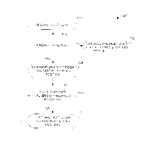
[0021] Referring now to Figure 4, an example method 300 for controlling (and
more
particularly selecting an opening angle of) an inlet door of a gas turbine
engine in
accordance with a first embodiment will now be described. The method 300 may
be
CA 2993579 2018-01-30
05002993-2097CA
96664
implemented by the computing device 200 of Figure 3. The method 300 comprises
the step 302 of receiving input data 302 (e.g. from the aircraft), which is
processed
in subsequent steps of the method 300. In particular, at step 304, the method
300
processes the input data to assess whether the aircraft is airborne or on
ground.
This may comprise analyzing input data such as an air/ground signal (e.g. a
"Weight
On Wheels" (WOW) signal), which is indicative of whether the aircraft has
weight on
its wheels. It should however be understood that other suitable input data may
be
received and analyzed to determine whether the aircraft is airborne.
[0022] If it is determined at step 304 that the aircraft is not airborne, the
next step
306 is to command the APU inlet door to the "Fully Open" position, since no
ram
effect adversely impacts the ability to start the APU on ground. Otherwise, if
the
aircraft is airborne, the next step 308 is to command the APU inlet door to
the
"Partially Open" position. The method 300 then further processes the received
input
data (e.g. a measurement of the rotational speed of the APU) to assess whether
the
APU speed has reached a predetermined speed threshold (step 310). If it is
determined at step 310 that the predetermined APU speed threshold has been
reached, meaning that the end of the APU start sequence is approaching, the
method 300 flows to the step 306 of commanding the APU inlet door to the
"Fully
Open" position. Otherwise, if the predetermined APU speed threshold has not
been
reaches, the APU inlet door is held in the "Partially Open' position at step
312. The
method 300 then flows back to the step 310 of comparing the current value of
the
APU speed to the speed threshold.
[0023] The speed threshold is illustratively computed as per equation (1)
below:
st = s ¨ (a * t)
(1)
[0024] where st is the predetermined speed threshold in %, s is the APU
operating
speed in normal steady state (e.g. 100%), a is the APU acceleration rate in %
per
second, and t is the time (in seconds) required to move the APU inlet door
from the
"Partially Open" position to the "Fully Open" position. In one embodiment, the
value
of the speed threshold is set to 85% and is indicative of an end of the start
sequence
of the APU. It should however be understood that, depending on the APU
6
CA 2993579 2018-01-30
05002993-2097CA
96664
acceleration rate, a speed threshold of 80% or 90% may apply. In a preferred
embodiment, the speed threshold is therefore substantially 85%.
[0025] The value of the speed threshold at which the APU inlet door is
commanded
"Fully Open" is illustratively selected to minimize both the time during which
the APU
inlet door is in the "Partially Open" position and the APU is operating at RTL
and the
time during which the APU inlet door is in the "Fully Open" position and the
APU is
starting. In particular and as discussed herein, it is desirable to select the
value of
the speed threshold such that the APU inlet door is opened as late as possible
during (i.e. towards an end of) the APU start sequence and to ensure that the
APU
inlet door is in the "Fully Open" position when the APU reaches 100% speed. On
the
one hand, transitioning the APU inlet door to the "Fully Open" position before
the
APU speed reaches the threshold (e.g. 85% speed) would increase the airflow to
the compressor of the APU and would impact the ability of the APU to complete
the
start sequence. This could in turn slow down the APU's acceleration and
require
more time to achieve the RTL state. On the other hand, transitioning the door
to the
"Fully Open" position after the APU speed has reached the threshold (e.g. 85%
speed) could lead to the APU inlet door not being fully open once the APU
speed
reaches full operating speed. This could in turn lead to a temporarily
degraded APU
operation.
[0026] Figure 5 illustrates another example method 400 for controlling (and
more
particularly selecting an opening angle of) an inlet door of a gas turbine
engine in
accordance with a second embodiment. The method 400 may be implemented by
the computing device 200 of Figure 3. Similarly to the method 300 of Figure 4,
after
input data is received at step 402, it is determined (step 404) whether the
aircraft is
airborne. If the aircraft is on the ground, the method 400 commands the APU
inlet
door to the "Fully Open" position (step 406). If the aircraft is airborne, the
APU inlet
door is commanded to the "Partially Open" position (step 408) and the next
step 410
is to determine whether the APU has reached its full operating speed (i.e.
whether
the APU speed equals 100%). If this is not the case, the APU inlet door is
held in the
"Partially Open" position (step 412) and the method 400 flows back to step
410.
Otherwise, if the APU speed has reached its full operating speed, the next
step 414
is to command the APU inlet door to the "Fully Open" position. In order to
prevent
degraded operation and improve transient response right after load
application, step
7
CA 2993579 2018-01-30
05002993-2097CA
96664
414 further comprises delaying the time at which the RTL signal is output,
thereby
ensuring that load is applied to the APU once the APU inlet door is in the
"Fully
Open" position.
[0027] The above description is meant to be exemplary only, and one skilled in
the
art will recognize that changes may be made to the embodiments described
without
departing from the scope of the invention disclosed. Still other modifications
which
fall within the scope of the present invention will be apparent to those
skilled in the
art, in light of a review of this disclosure, and such modifications are
intended to fall
within the appended claims.
8
CA 2993579 2018-01-30