Note : Les descriptions sont présentées dans la langue officielle dans laquelle elles ont été soumises.
=
METHODS AND APPARATUS TO REDUCE NOISE IN MOTOR ASSEMBLIES
RELATED APPLICATIONS
[0001] This patent claims the benefit under 35 U.S.C. 119(e) to U.S.
Provisional
Application No. 62/455,366, titled "METHODS AND APPARATUS TO REDUCE NOISE IN
ARCHITECTURAL COVERINGS," filed February 6, 2017, and to U.S. Provisional
Application
No. 62/568,697, titled "METHODS AND APPARATUS TO REDUCE NOISE IN
ARCHITECTURAL COVERINGS," filed October 5, 2017, both of which are
incorporated
herein by this reference in their entireties.
FIELD OF THE DISCLOSURE
[0002] This disclosure relates generally to motors and, more
particularly, to methods and
apparatus to reduce noise in motor assemblies.
BACKGROUND
[0003] Motor assemblies are used in many applications to provide power
to a downstream or
driven member. Motor assemblies include a motor with an output shaft that is
operatively
coupled to the driven member. The connection between the motor output shaft
and the driven
member often generates significant noise due to vibrations between the
components.
[0004] For instance, architectural coverings such as roller blinds,
vertical window coverings,
horizontal window coverings, and spring-loaded window coverings provide
shading and privacy.
Such architectural coverings often include a motorized assembly coupled with a
covering fabric
or other shading material. In particular, a motor rotates a roller tube or
lift rod to raise or lower
- 1 -
CA 2993964 2018-02-05
the cover or shading material. These motorized assemblies often include
complex coupling
devices with many parts or components that connect an output shaft of the
motor to the roller
tube or lift rod. As a result, these motorized assemblies tend to be loud and
noisy when
operating due to vibration of the parts and components, which is a nuisance to
the user and/or
others in the area.
BRIEF DESCRIPTION OF THE DRAWINGS
[0005] Implementations of motor assemblies constructed in accordance with
principles of
inventions disclosed herein will be described with reference to the following
drawings, which are
not to be considered as limiting, but rather, illustrations of examples of
manners of implementing
principles of the disclosure. For example, while implementations of motor
assemblies within
architectural coverings are described, many other implementations will occur
to persons of
ordinary skill in the art upon reading this disclosure.
[0006] FIG. 1 is a perspective view of an example of an architectural
covering employing an
example of a drive coupling constructed in accordance with one or more
principles of this
disclosure.
[0007] FIG. 2 is an exploded view of the example of the drive coupling of
FIG. 1.
[0008] FIG. 3 is a perspective view of the example of the drive coupling of
FIG. 2 in a
partially assembled state.
[0009] FIG. 4 is a perspective view of the example of the drive coupling of
FIG. 2 in an
assembled state.
[0010] FIG. 5 is another perspective view of the example of the drive
coupling of FIG. 2 in
an assembled state.
- 2 -
CA 2993964 2018-02-05
[0011] FIG. 6A is a side view of an example of an elastic ring employed in
the example of
the drive coupling of FIG. 1.
[0012] FIG. 6B is a top view of the example of the elastic ring of FIG. 6A.
[0013] FIG. 7 is an end view of the example of the drive coupling of FIG. 1
implemented
with an example of a roller tube.
[0014] FIG. 8 is an end view of the example of the drive coupling of FIG. 1
implemented
with another example of a roller tube.
[0015] FIG. 9 illustrates an example of a tube adapter that may be
implemented with the
example of the drive coupling of FIG. 1.
[0016] FIG. 10 illustrates another example of a tube adapter that may be
implemented with
the example of the drive coupling of FIG. 1.
[0017] FIG. 11 illustrates another example of a tube adapter that may be
implemented with
the example of the drive coupling of FIG. 1.
[0018] FIG. 12 is a perspective view of an example of a driver, which may
be implemented
in the example of the drive coupling of FIG. 1, and which may be constructed
using a die casting
process.
[0019] FIG. 13 is a cross-sectional view of the example of the driver of
FIG. 12 taken along
line A-A of FIG. 12.
[0020] FIG. 14 illustrates the example of the driver of FIG. 13 showing an
example of a pin
arrangement that may be used to form openings in the example of the driver
during the die
casting process.
- 3 -
CA 2993964 2018-02-05
[0021] FIG. 15 illustrates the example of the driver of FIG. 13 showing a
motor output shaft
inserted into an opening formed in the example of the driver using the pin
arrangement of FIG.
14.
[0022] FIG. 16 is a perspective view of an example of an architectural
covering employing
another example of a drive coupling constructed in accordance with one or more
principles of
this disclosure.
[0023] FIG. 17 is an exploded view of the example of the drive coupling of
FIG. 16.
[0024] FIG. 18 is a perspective view of the example of the drive coupling
of FIG. 16 in a
partially assembled state.
[0025] FIG. 19 is a perspective view of the example of the drive coupling
of FIG. 16 in an
assembled state.
[0026] FIG. 20 is another perspective view of the example of the drive
coupling of FIG. 16
in an assembled state.
[0027] FIG. 21A is a side view of the example of the drive coupling of FIG.
16 in which a
second driver of the drive coupling is tilted about an axis and is unaligned
with respect to a first
driver of the drive coupling.
[0028] FIG. 21B is a side view of the example of the drive coupling of FIG.
21A in which
the second driver is tilted about another axis and is unaligned with respect
to the first driver.
[0029] FIG. 22A is a side view of the example of the drive coupling of FIG.
16 in which a
second driver of the drive coupling is misaligned with a first driver of the
drive coupling.
[0030] FIG. 22B is a plan view of a hub of the drive coupling of FIG. 22A
showing
movement of posts of the first and second drivers.
- 4 -
CA 2993964 2018-02-05
,
,
[0031] FIG. 23A is an exploded view of another example of a drive
coupling that may be
used with an architectural covering.
[0032] FIG. 23B is a side view of the example of the drive coupling of
FIG. 23A in an
assembled state.
[0033] FIG. 24 illustrates an example of an architectural covering
including an example of a
headrail having an example of a valance with sound-dampening material
constructed in
accordance with one or principles of this disclosure.
[0034] FIGS. 25A and 25B illustrate an example of a clip used to
couple an example of a
layer of sound-dampening material to a back side of the example of the valance
of FIG. 24.
[0035] FIGS. 26A and 26B illustrate another example in which an
example of a layer of
sound-dampening material is coupled to a back side of an example of a valance
and constructed
in accordance with one or more principles of this disclosure.
[0036] FIG. 27 illustrates an example of a valance having a pocket
into which sound-
dampening material may be disposed and constructed in accordance with one or
more principles
of this disclosure.
DETAILED DESCRIPTION
[0037] Disclosed herein are example drive couplings used to reduce
potential noise
generated by a connection between a driving member, such as an output shaft of
a motor of a
motor assembly, and a downstream or driven member. While some of the example
drive
couplings and other related aspects disclosed herein are described in
connection with motor
assemblies in architectural coverings, any of the examples disclosed herein
can likewise be
implemented with motor assemblies in other types of devices or systems, such
as material
- 5 -
CA 2993964 2018-02-05
handling systems, robotics, belt or chain drive systems, and/or any other type
of motor assembly
having a connection between an output shaft (a driving member) and a
downstream driven
member. The example drive couplings and/or other aspects disclosed herein can
be used with
these motor assemblies to similarly reduce vibration (and, thus, potential
noise) between a motor
and/or driving member and a downstream driven member. Thus, the example drive
couplings
and/or others aspects are not limited to architectural coverings.
[0038] Some architectural coverings include a motor assembly to extend or
retract a covering
(e.g., by rotating a roller tube) to cover or uncover an architectural opening
and/or structure. For
example, in a vertically extending covering, a motor operates in one direction
to raise the
covering and in the opposite direction to the lower the covering. The motor is
coupled to a
rotating member, such as a roller tube or a lift rod. When rotated, the
covering or a cord
operating the covering may be wound or unwound by the rotating member to raise
or lower the
corresponding covering. Known architectural coverings, including motorized
coverings, non-
motorized coverings, and/or dual operation coverings, typically generate a
significant amount of
audible noise, which can become a nuisance to those in the surrounding area of
the architectural
covering.
[0039] Disclosed herein are example methods and apparatus that reduce
potential noise
generated by architectural coverings. Aspects of this disclosure may be
implemented to reduce
potential noise from any type of motorized, non-motorized, and/or dual
operation architectural
covering. Thus, aspects of this disclosure result in quieter, more desirable
architectural
coverings. While humans are capable of hearing frequencies of between 20 hertz
(Hz) ¨ 20 kilo-
Hz (kHz) (which are considered audible frequencies), certain frequencies have
a greater
perceived loudness to humans. For instance, frequencies of between 1 kHz and
5kHz are
- 6 -
CA 2993964 2018-02-05
generally perceived as louder than other audible frequencies, even if the
amplitude or strength of
the noise is in this range is less than the amplitude or strength of the noise
in a frequency outside
this range. Example aspects disclosed herein result in reduced noise (e.g.,
from 37 decibels (db)
to 32db) in this range of frequencies (as well as other frequencies outside
the range) and, thus,
create a more desirable environment for a user. Aspects of this disclosure may
also reduce the
number of parts and components in an architectural covering, which decreases
manufacturing
costs, decreases assembly time, and increases the useful life of the
architectural covering (e.g.,
by decreasing the number of parts and components that would otherwise be
subject to wear and,
thus, failure over time).
[0040] In accordance with one aspect of the disclosure, an architectural
covering includes a
drive coupling that transfers rotational motion from an output shaft of a
motor to a rotating
member (e.g., a roller tube, a lift rod, etc.), arranged and configured to
raise or lower a covering.
Some such drive couplings include one or more vibration-absorbers (which may
be referred to
isolators), such as sound-dampening elastic rings, which reduce potential
noise generated by
vibration between the parts of the architectural covering. Some such drive
couplings also
employ significantly fewer parts or components than known architectural
coverings and, thus,
further reduce vibrations between the parts and components. By using few parts
or components,
the example drive couplings are also less expensive to manufacture and result
in reduced
assembly time. The example drive couplings disclosed herein may be used with
any type of
architectural covering such as conventional draperies, shutters, horizontal
and vertical blinds, and
various other kinds of shades, including roller and cellular shades, etc.
[0041] In accordance with some aspects of this disclosure, the drive
coupling includes a
driver configured to be coupled to and rotated by an output shaft of a motor.
Such a driver,
- 7 -
CA 2993964 2018-02-05
=
which may be referred to as an input driver, interfaces with a driven member,
which may be
referred to as an output driver, that is coupled to a rotating member (e.g., a
roller tube, a lift rod,
etc.) for extending or retracting an architectural covering. As such, the
input driver rotates the
driven member to rotate the corresponding rotating member to extend or retract
the covering.
[0042]
In accordance with one aspect of the disclosure, the driven member is
implemented as
an adapter, such as a tube adapter, that has one or more features to engage
matching feature(s) on
a rotating member, such as a roller tube. For example, the motor and drive
coupling may be
disposed within the roller tube, and the tube adapter may engage an inside
surface of the roller
tube. The tube adapter rotates with the motor output shaft. Thus, the tube
adapter transfers
rotational motion of the motor output shaft to the rotating member to extend
or retract the
corresponding covering.
[0043] As mentioned above, in one aspect of the disclosure, the drive coupling
includes an input
driver to be coupled to the output shaft of the motor. The input driver
interfaces with the tube
adapter (e.g., the driven member) to rotate the tube adapter when the motor
output shaft is
rotated. In other words, the input driver operates to rotate the tube adapter
and, thus, rotate the
roller tube. In one aspect of the disclosure, one or more vibration-absorbers
are disposed
between a vibration generator, such as the motor and/or the input driver
(which is coupled to the
output shaft of the motor), and a driven member, such as the tube adapter. The
vibration-
absorber(s) may be constructed of a lower durometer material, such as a
material that absorbs
vibrations between the parts of the drive coupling and, thus, reduces
potential noise that would
otherwise be caused thereby. In some examples, this is accomplished due to the
shape of the
vibration-absorber(s), which may have relatively thin wall sections (e.g.,
about 0.032 inches
(0.8128 millimeters (mm)) disposed in compression during use, which allows for
isolating
- 8 -
CA 2993964 2018-02-05
,
,
vibration while minimizing backlash (even with lower durometer material (e.g.,
50 Shore A)). In
other words, because the durometer is low, vibration damping is optimized
while the amount of
material that allows compression is minimized. Known spider couplings
interpose a rigid, high
durometer spider (55 Shore D) between a driving jaw coupling and a driven jaw
coupling to
allow for misalignment (e.g., slop or play) between the two jaw couplings.
However, unlike
these known spider couplings, the example drive couplings disclosed herein
interpose one or
more vibration-absorber(s), such as a vibration-absorber of a lower durometer
material (e.g., 50
Shore A), between a vibration generator, such as the motor and/or the input
driver, and the one or
more downstream/driven member(s), such as the second driver, the tube adapter,
the roller tube,
the headrail, another drive shaft, etc., to reduce vibrations between the
part(s). In other words,
the vibration-absorber(s) isolate(s) the vibration generator from the
downstream/driven
member(s) that would otherwise amplify and/or increase the vibrations and
noise. In one aspect
of the disclosure, the vibration-absorber(s) (of relatively softer material)
create a relatively tight
interface between the vibration generator and the downstream/driven member(s)
that reduces
vibrations and, thus, reduces noise that would otherwise be caused between
these parts and/or
other downstream/driven member(s). Further, in some instances, the vibration-
absorbers provide
intimate contact between the driving member, such as the driver, and the
driven member, such as
the rotating member, to minimize backlash, which may otherwise be caused by a
covering that
disposes the weight alternately from one side to the other side of the
rotating member.
100441
In accordance with one aspect of the disclosure, the one or more
vibration-absorber(s)
are coupled to a portion of the driver. Further, the driven member is
operatively engaged with
the one or more vibration-absorber(s). As used herein, the terms "operatively
engaged,"
"operatively engages," "operatively engaging," or variations thereof mean a
first part is in direct
- 9 -
CA 2993964 2018-02-05
and/or indirect contact with a second part (e.g., indirect contact via one or
more intermediary
parts). As such, when the driver is rotated, rotational motion is transferred
to the driven member
(and, thus, the rotating member) via the vibration-absorber(s).
[0045] In accordance with one aspect of the disclosure, the driver has a
set of mounts to
which a driven member, such as tube adapter, may be mounted. In one aspect of
the disclosure,
the mounts are posts that extend parallel to and spaced apart from a
rotational axis of the driver.
As the driver rotates, the posts rotate about the rotational axis. In
accordance with one aspect of
the disclosure, the tube adapter includes a central portion with one or more
arms (e.g., having
features to engage the rotating member) extending outwardly from the central
portion. The
central portion is disposed between the posts of the driver and the arms
extend outwardly,
beyond the posts to engage the roller tube. Thus, the output shaft of the
motor rotates the driver,
which rotates the tube adapter and, thus, rotates the roller tube.
[0046] In accordance with one aspect of the disclosure, to reduce vibration
between the
driver and the tube adapter, the drive coupling includes one or more
vibrations-absorbers
interposed between the driver and the tube adapter. In one aspect of the
disclosure, a set of
vibration-absorbers, hereinafter "elastic rings" for the sake of convenience
without intent to
limit, are coupled to portions of the driver and interposed between the driver
and the tube
adapter. For example, the drive coupling may include elastic rings (e.g., non-
viscoelastic rings),
such as grommets, mounted on the posts. In particular, one elastic ring is
disposed on each of
the posts. The elastic rings are engaged with and may be constructed to carry
the tube adapter.
Thus, the elastic rings isolate the tube adapter from the driver. In
accordance with one aspect of
the disclosure, the tube adapter includes a web or rib between each pair of
adjacent arms. The
elastic rings may be disposed between the adjacent arms with the web or rib
disposed in the
- 10 -
CA 2993964 2018-02-05
groove of the respective elastic ring. The interface between the webs and the
elastic ring and/or
between the elastic ring and the posts result in less noise generated by the
parts of the
architectural covering. In accordance with one aspect of the disclosure, the
elastic rings are
constructed of nitrile rubber (otherwise known as Buna-N).
[0047] In accordance with another aspect of this disclosure, the drive
coupling includes a
driver, implemented as a first driver (e.g., the input driver) that is coupled
to the output shaft of
the motor, which is connected to a driven member, implemented as a similarly
shaped second
driver (e.g., the driven member, the output driver, etc.) that is coupled to a
rotating member, such
as a lift rod, a drive shaft, etc. The first driver may be connected to the
second driver via one or
more posts and vibration-absorber(s) (e.g., as described above) using an
intermediate generally
clover-shaped disc or hub to transfer torque, while isolating vibration
between the driver and the
driven member. In other words, when the motor output shaft is rotated, the
first driver interfaces
with the hub via the one or more vibration-absorber(s), which interfaces with
the second driver
via one or more vibration-absorber(s) to rotate the rotating member, such as a
driven shaft or lift
rod. In one aspect of this disclosure, one or more spools with lift cords are
coupled to the lift
rod. The lift rod may be rotated to wind or unwind the lift cord(s) to extend
or retract the
corresponding cover in a manner known in the art or to be developed.
[0048] Similar to the drive coupling disclosed above, one or more vibration-
absorbers may
be disposed between the first driver and the second driver (e.g., the driven
member) to reduce
potential noise that could otherwise result from operation of the parts
connecting the motor and
any downstream/driven parts. The vibration-absorber(s) isolate the vibration
source, such as the
motor and/or the first driver, from the downstream/driven member(s), such as
the second driver,
the lift rod, the headrail, etc. that could otherwise amplify and/or increase
the vibrations and
- 1 1 -
CA 2993964 2018-02-05
noise. Similar to the vibration-absorbers disclosed above, the vibration-
absorber(s) may be
constructed of relatively soft material that creates a tight interface between
the vibration
generator and the downstream/driven member(s), which reduces movement between
these parts.
Further, the vibration-absorbers may compress or deform to absorb movement or
vibration
between the parts. Thus, the vibration-absorbers reduce potential vibrations
(and, thus, reduce
noise) that would otherwise be caused between these parts and/or other
downstream/driven
member(s) using a looser connection and more rigid parts.
[0049] In accordance with one aspect of the disclosure, the first driver
has a first set of
mounts and the second driver has a second set of mounts. In one aspect of the
disclosure, the
mounts are posts. For example, the first driver may have a first set of posts
that extend outward
toward the second driver, and the second driver may have a second set of posts
that extend
outward toward the first driver. In one aspect of the disclosure, the drive
coupling includes a hub
disposed between the first set of posts and the second set of posts. The
output shaft of the motor
rotates the first driver, which rotates the hub, which rotates the second
driver and, thus, rotates
the rotating member.
[0050] In accordance with one aspect of the disclosure, to reduce vibration
between the first
driver, the hub and the second driver, the drive coupling includes one or more
vibration-
absorbers interposed between the first driver and the hub, and between the hub
and the second
driver. Similar to the vibration-absorbers disclosed above, the vibration-
absorbers may be
implemented as elastic rings, such as grommets. In one aspect of the
disclosure, one elastic ring
is disposed on each of the first set of posts and the second set of posts.
Thus, the elastic rings
separate the first driver from the hub and separate the second driver from the
hub. In accordance
with one aspect of the disclosure, the hub includes a plurality of notches and
the elastic rings are
- 12 -
CA 2993964 2018-02-05
,
,
disposed in the notches such that an outer edge of the hub extends into
grooves in the outer edges
of the elastic rings. The interface between the posts, the elastic rings and
the hub results in less
noise generated by the parts of the architectural covering. In accordance with
one aspect of the
disclosure, the elastic rings are constructed of nitrile rubber (otherwise
known as Buna-N).
[0051] In some instances, the output shaft of the motor and the
rotating member may be
misaligned. For example, due to tolerances in manufacturing of the mounts that
hold the motor
and/or the rotating member, the axis of the motor output shaft and the axis of
the rotating
member may not be perfectly aligned. In known coupling assemblies, this
misalignment causes
increased wear and, thus, degradation of the parts of the coupling assembly.
In accordance with
one aspect of the disclosure, the second driver may be tiltable with respect
to the rotational axis
of the first driver, which enables the drive coupling to transfer rotational
motion even when the
motor output shaft and the axis of the rotating member are not aligned. The
vibration-absorbers
compress or deform, which allows the posts of the first driver and/or the
second driver to be
tilted with respect to the hub and, thus, to the other of the first driver
and/or the second driver.
As such, the rotational axis of the second driver (and, thus, the rotating
member) can be
misaligned with the rotational axis of the first driver and the output shaft
of the motor while still
being rotatably coupled to the first driver. This advantageously enables the
drive coupling to
transfer rotational motion even when the output shaft of the motor and the
rotating member (e.g.,
the lift rod) are not axially aligned and without causing addition wear on the
parts of the drive
coupling.
[0052] Also disclosed herein are examples of valances having sound-
dampening material for
attenuating potential noise generated by architectural coverings. As used
herein, the term
"valance" means structure that is to be disposed in front of and/or over an
architectural covering
- 13 -
CA 2993964 2018-02-05
to hide and/or otherwise block the view of at least a portion of the
architectural covering. Some
valances are decorative and have aesthetic features. For example, a valance
may be disposed
outside a window frame to hide an architectural covering located in the window
frame. The
valance may be coupled to the architectural covering and/or to the
architectural structure (e.g.,
the window frame). In accordance with one aspect of the disclosure, a layer or
strip of sound-
dampening material is coupled to a back side of the valance facing the
architectural covering. In
accordance with one aspect of the disclosure, the sound-dampening material is
butyl rubber. The
sound-dampening material attenuates or dampens sound generated by the
architectural covering.
As a result, example valances greatly reduce potential noise generated by
architectural coverings
(e.g., motorized coverings).
[0053] In accordance with one aspect of the disclosure, a valance is part
of a headrail that is
used to mount the architectural covering to an architectural structure (e.g.,
a window frame). For
example, a headrail may include a top mounting plate and a valance extending
downward from
the top mounting plate. The top mounting plate may be coupled (e.g., via one
or more screws) to
the architectural structure to mount the headrail (and, thus, the
architectural covering) to the
architectural structure. The valance extends downwardly from the top mounting
plate to cover
and/or otherwise obstruct the view of the architectural covering. In
accordance with other
aspects of the disclosure, the valance may be separate from the top mounting
plate and separately
coupled to the outside of the architectural covering and/or to the
architectural structure.
[0054] Also disclosed herein are examples of techniques to couple the layer
of sound-
dampening material to the back side of the valance. In accordance with one
aspect of the
disclosure, a clip is used to couple the layer of sound-dampening material to
the back side of the
valance. For example, the sound-dampening material may be coupled to a back
side of the clip
- 14 -
CA 2993964 2018-02-05
(e.g., via an adhesive). In one aspect of the disclosure, the back side of the
valance includes a
first connector (e.g., a female connector) and the back side of the clip has a
second connector
(e.g., a male connector) to mate with the first connector. The clip may be
mounted to the back
side of the valance (via the connectors), thereby holding the sound-dampening
material between
the clip and the valance and, thus, coupling the sound-dampening material to
the back side of the
valance. In some instances, using the clip prevents contact between the
covering and the strip of
sound-dampening material (which may otherwise leave marks or coloring on the
covering
material). Additionally or alternatively, the layer of sound-dampening
material may include an
adhesive side, which may be contacted against the back side of the valance.
[0055] Also disclosed herein are example methods of manufacturing a valance
and the
example valances resulting from such methods. In accordance with one aspect of
the disclosure,
the clip and the layer of sound-dampening material are constructed by
extruding the clip and the
sound-dampening material simultaneously. As such, the layer of sound-dampening
material is
coupled (e.g., bonded) to the back side of the clip. In accordance with one
aspect of the
disclosure, the valance is also manufactured via an extrusion process. Then,
the clip may be
coupled to the back side of the valance to couple the sound-dampening material
to the back side
of the valance. In accordance with another aspect of the disclosure, a layer
of sound-dampening
material may be co-extruded onto a back side of a valance. In some instances,
the valance
includes a pocket or recess, and the layer of sound-dampening material is
extruded into the
recess. In accordance with other aspects of the disclosure, other types of
manufacturing
processes may be implemented.
[0056] In some aspects of this disclosure, a drive coupling as disclosed
herein may be
implemented in an architectural covering also having a valance with sound-
dampening material
- 15 -
CA 2993964 2018-02-05
as disclosed herein. In some instances, the combination of these features
produces improved
noise reduction compared to each feature used by itself In accordance with
some aspects of this
disclosure, the combination of features may also be implemented with one or
more other noise-
reduction features. In accordance with other aspects of this disclosure, the
example drive
couplings and the example valances with sound-dampening material may be used
separately
from one another and/or in combination with other noise-reduction features.
[0057] All apparatuses and methods discussed in this document and
illustrated in the
accompanying drawings are examples of apparatuses and/or methods implemented
in accordance
with one or more principles of this disclosure, which principles may be
applied singly or in
combination. These examples are not the only way to implement these principles
but are merely
examples. Other examples of manners of implementing the disclosed principles
will occur to a
person of ordinary skill in the art upon reading this disclosure. It will be
appreciated that the
drawings illustrate examples of embodiments of the disclosure incorporating
one or more
principles or features, and thus reference to or description of a particular
structure or element in
the figures is to be understood as reference to or description of an example
of an embodiment,
but not necessarily the only manner of embodying the disclosure.
[0058] Turning now to the figures, FIG. 1 illustrates an example of an
architectural covering
100 having a covering 102. Architectural covering 100 may be used to cover an
architectural
structure, such as a wall, and/or an architectural opening, such as a window,
a door, a sky light,
an archway, etc. In accordance with one aspect of this disclosure, an example
drive coupling
may be coupled to the output shaft of the motor to transfer rotational motion
to the roller tube or
other rotating member that moves a covering in one direction or the other.
Example drive
- 16 -
CA 2993964 2018-02-05
couplings disclosed herein greatly reduce potential noise that would otherwise
be generated by
the connection between the motor and the rotating member.
[0059] For example, in the illustrated example of FIG. 1, architectural
covering 100 includes
a motor 104 and a rotating member, implemented as a roller tube 106 (shown in
dashed lines).
Covering 102 is wound around or unwound from roller tube 106 to extend or
retract covering
102. In other words, motor 104 operates to rotate roller tube 106 in one
direction to retract
covering 102 (e.g., raise covering 102 or otherwise uncover an architectural
structure and/or
opening) and rotate roller tube 106 in the opposite direction to extend the
corresponding covering
102 (e.g., lower covering 102 or otherwise cover the architectural structure
and/or opening).
Motor 104 may be powered by any combination of internal and/or external power
line
connections, power from a wall outlet, battery(ies), fuel cells, solar panels,
wind powered
generators, and/or any other power source. Motor 104 has a motor output shaft
108.
[0060] To transfer rotational motion from motor output shaft 108 to roller
tube 106, example
architectural covering 100 includes an example drive coupling 110. Drive
coupling 110 is
coupled to and rotates with motor output shaft 108. Additionally, drive
coupling 110 is coupled
to roller tube 106. As such, when motor 104 rotates motor output shaft 108,
drive coupling 110
transfers the rotational motion to roller tube 106.
[0061] In the illustrated example of FIG. 1, roller tube 106 is disposed
outside and concentric
with motor 104. In other words, motor 104 is disposed within roller tube 106
and operates to
rotate roller tube 106 from within roller tube 106. In other aspects of this
disclosure, motor 104
and roller tube 106 may be arranged in other configurations. For example,
motor 104 may be
disposed outside roller tube 106 and aligned with roller tube 106 (e.g., end-
to-end). Further,
while example architectural covering 100 is illustrated with example covering
102, it is
- 17 -
CA 2993964 2018-02-05
understood that example architectural covering 100 may be implemented with any
type of
covering, such as conventional draperies, shutters, horizontal and vertical
blinds, and various
other kinds of shades, including roller and cellular shades, etc.
[0062] In accordance with one aspect of this disclosure, the drive coupling
includes one or
more vibration-absorbers that are used to reduce vibration between the parts
of the architectural
covering. For example, the drive coupling may include a driver that connects
to the output shaft
of the motor and a tube adapter that connects to the roller tube. The driver
rotates the tube
adapter to rotate the roller tube. In accordance with one aspect of this
disclosure, vibration-
absorbers are utilized between the driver and the tube adapter to reduce
vibration and, thus, to
reduce potential noise in an architectural covering. For example, the driver
may include a set of
mounting structures, such as posts, extending outwardly from a plate in a
direction that is parallel
to and offset from a rotational axis of the driver. The tube adapter may
include a central portion,
disposed between the posts, and a set of arms extending outwardly from the
central portion
beyond the posts to engage the roller tube. As the driver rotates, the posts
rotate the tube adapter
and, thus, rotate the roller. In accordance with one aspect of the disclosure,
the vibration-
absorbers are located between the posts of the driver and the tube adapter. In
accordance with
one aspect of this disclosure, the vibration-absorbers may be embodied as
elastic rings. For
example, an elastic ring may be disposed on each post, and the arms of the
tube adapter may be
engaged by the elastic rings. Thus, the tube adapter is indirectly coupled to
the driver by the
elastic rings. In one aspect of the disclosure, the elastic rings are
implemented as grommets.
The interface between the driver, the vibration-absorbers, and the tube
adapter results in
decreased vibration, which greatly reduces and/or eliminates noise that would
otherwise be
generated by a traditional connection.
- 18 -
CA 2993964 2018-02-05
[0063] For example, FIG. 2 is an exploded view of example drive coupling
110. In the
illustrated example, drive coupling 110 includes a driver 200, a set of
elastic rings 202, a tube
adapter 204 (e.g., a cog) and a retainer 206. Driver 200 includes a mounting
shaft 208 that is
configured to be coupled to motor output shaft 108 of motor 104 (FIG. 1). In
one aspect of this
disclosure, mounting shaft 208 includes an opening to receive motor output
shaft 108, as
disclosed in further detail in conjunction with FIG. 5. When coupled to motor
output shaft 108,
motor 104 rotates driver 200 about a rotational axis 210 (e.g., a central or
longitudinal axis of
driver 200). In one aspect of this disclosure, rotational axis 210 is
substantially aligned with the
rotational axis of motor output shaft 108 of motor 104. In the illustrated
example of FIG. 2,
driver 200 includes a plate 212 coupled to mounting shaft 208. Plate 212 is
oriented
perpendicular to rotational axis 210. Driver 200 includes a set of posts 214
that are coupled to
and extend from a face 216 of plate 212. In the illustrated example, driver
200 includes four
posts 214. However, in other aspects of this disclosure, driver 200 may
include more (e.g., five
posts, six posts, etc.) or fewer posts (e.g., three posts, two posts, one
post). Posts 214 are parallel
to and offset from rotational axis 210. As such, when driver 200 is rotated,
posts 214 rotate
around rotational axis 210. In the illustrated example of FIG. 2, posts 214
are spaced equidistant
from rotational axis 210 and are arranged in a square pattern around
rotational axis 210.
However, in other aspects of this disclosure, posts 214 may be arranged in
other configurations
and/or may be spaced closer to or further from rotational axis 210 and/or one
another.
[0064] In the illustrated example of FIG. 2, plate 212 includes raised
surfaces 218 (one of
which is referenced in FIG. 2) where posts 214 extend from face 216 of plate
212. When drive
coupling 110 is assembled (as illustrated in FIGS. 4 and 5), raised surfaces
218 separate elastic
rings 202 from face 216 of plate 212. In other aspects, no raised surfaces may
be implemented.
- 19 -
CA 2993964 2018-02-05
In one aspect of this disclosure, driver 200 is constructed as a substantially
unitary part or
component. For example, driver 200 may be molded as a single part or component
and/or
machined from a single piece of material (e.g., zinc). In another aspect of
this disclosure, driver
200 may be constructed of multiple parts or components that are coupled
together (e.g., posts
214 may be welded to plate 212, plate 212 may be welded to mounting shaft 208,
etc.).
[0065] In one aspect of the disclosure, a tube adapter may be included in
the drive coupling
to transfer rotational motion from the driver to the roller tube. The tube
adapter may include one
or more features that mate with or engage one or more features on the roller
tube. In accordance
with one aspect of this disclosure, the tube adapter includes a central
portion and a plurality of
arms extending from the central portion. The arms may include the features to
engage the roller
tube (e.g., to engage an inner surface of the roller tube). In accordance with
one aspect of this
disclosure, the central portion of the tube adapter is disposed between the
posts of the driver, and
the arms extend outwardly beyond the posts to engage the roller tube. In one
aspect of this
disclosure, the tube adapter may be interchangeable with one or more other
tube adapters having
different features and/or sizes for interfacing with other roller tubes.
[0066] For example, referring back to FIG. 2, to transfer rotational motion
from driver 200 to
roller tube 106 (FIG. 1), drive coupling 110 includes tube adapter 204. Tube
adapter 204
engages roller tube 106. In particular, tube adapter 204 includes arms 220
that extend outwardly
from a central portion 222. In the illustrated example, tube adapter 204
includes four arms 220.
However, in other aspects of this disclosure, tube adapter 204 may include
more or fewer arms
220. An end 224 of each arm 220 includes a first feature, implemented as a
slot 226 (e.g., a
female feature) (one of which is referenced in FIG. 2), that mates with a
second feature (e.g., a
male feature) on an inner surface of roller tube 106, as disclosed in further
detail in conjunction
- 20 -
CA 2993964 2018-02-05
,
with FIG. 7. In the illustrated example of FIG. 2, arms 220 form a cross-
shape. Curved or arc-
shaped notches 228 are formed between adjacent arms 220. In the illustrated
example, tube
adapter 204 has four notches 228, one between each adjacent pair of arms 220.
In one aspect of
the disclosure, the number of posts 214 (and, thus, the number of elastic
rings 202) corresponds
to the number of notches 228. In one aspect of the disclosure, using four
posts 214 with four
elastic rings 202 results the optimal reduction in noise generated by
architectural covering 100.
In other aspects of this disclosure, with more or fewer arms 220, tube adapter
204 may have
more or fewer notches 228 and, thus, more or fewer posts 214 may be used.
[0067] In accordance with one aspect of this disclosure, one or more parts
for absorbing
vibration are included in the drive coupling to dampen vibration and, thus,
reduce potential
noise. The vibration-absorber(s) may be constructed of a lower durometer
material (e.g., Shore
A material). The vibration-absorber(s) may be interposed in one or more
locations between the
relatively harder part(s) of the drive coupling. For example, the vibration-
absorbers may be
disposed between the driver and a driven member, such as the tube adapter. In
one aspect of this
disclosure, the vibration-absorbers are implemented as elastic rings. For
example, referring to
FIG. 1, drive coupling 110 includes elastic rings 202. In the illustrated
example, elastic rings
202 are implemented as grommets. However, in other aspects of the disclosure,
other types of
elastic rings may be implemented. Each elastic ring 202 includes an opening
230 to receive a
respective one of posts 214. In the illustrated example, each elastic ring 202
includes a groove
232 (one of which is referenced in FIG. 2) formed in an outer edge 234 of the
respective elastic
ring 202. To mate with grooves 232, each notch 228 on tube adapter 204
includes a rib or web
236 (one of which is referenced in FIG. 2). Each web 236 is located between
adjacent arms 220.
As illustrated in FIG. 3, when drive coupling 110 is being assembled, elastic
rings 202 are
-21 -
CA 2993964 2018-02-05
inserted into notches 228. In this arrangement, webs 236 (FIG. 2) fit into
grooves 232 of elastic
rings 202.
[0068] In the illustrated example, elastic rings 202 may be used to carry
tube adapter 204
when elastic rings 202 are placed on posts 214. In other words, the elastic
rings 202 are
interposed between driver 200 and tube adapter 204 to reduce (e.g., minimize)
or eliminate
contact between driver 200 and tube adapter 204. In the illustrated example,
tube adapter 204 is
operatively engaged with elastic rings 202. Elastic rings 202 absorb vibration
that may
otherwise cause acoustic waves (e.g., sound) between driver 200 and tube
adapter 204 (and, thus,
roller tube 106 (FIG. 1)). Further, in one aspect of the disclosure, elastic
rings 202 may be
coupled to posts 214 and tube adapter 204 (e.g., via webs 236 and grooves 232)
with minimal
clearance, which reduces backlash. For instance, the thin wall sections (on
either side of grooves
232) of elastic rings 202 may be disposed in compression during use, which
allows for isolating
vibration while minimizing backlash. Backlash is the clearance between the
forward motion and
backward motion between driver 200 and tube adapter 204 that results when
switching direction
of rotation (e.g., between extending and retracting covering 102 (FIG. 1)).
Backlash may be an
effect generated by a covering that disposes the weight alternately from one
side to the other side
of a rotating member. Elastic rings 202 keep driver 200 and tube adapter 204
in relatively
intimate contact without excess clearance to minimize backlash.
[0069] In one aspect of the disclosure, elastic rings 202 are constructed
of a material that is
resilient or elastic enough (e.g., non-viscoelastic) to return to its original
shape after being
compressed, but soft enough to be compressed when torqued between driver 200
and tube
adapter 204 (and, thus, to absorb vibrations therebetween). For example,
elastic rings 202 may
be constructed of materials having a durometer of about 40 Shore A and above,
at increments of
- 22 -
CA 2993964 2018-02-05
1, and/or a durometer of about 65 Shore A and below, at increments of 1. In
accordance with
one aspect of the disclosure, elastic rings 202 are constructed of 50 Shore A
nitrile rubber
(known as Buna-N). In other aspects of the disclosure, elastic rings 202 may
be constructed of
other materials, such as a polyurethane. Driver 200 and tube adapter 204 may
be constructed of
a higher durometer materials (e.g., to withstand higher torques). For example,
driver 200 may be
constructed of zine, nylon, and/or a polycarbonate alloy, and tube adapter 204
may be
constructed of acetal, which has optimal lubricity and toughness.
Alternatively, in other aspects
of the disclosure, driver 200 and/or tube adapter 204 may be constructed of
other materials.
[0070] In accordance with one aspect of this disclosure, a retainer may be
provided to hold
elastic rings (and, thus, tube adapter) on the driver. For example, referring
back to FIG. 2, drive
coupling 110 includes retainer 206, which may be coupled to posts 214 of
driver 200 after elastic
rings 202 and tube adapter 204 are coupled to driver 200. In particular,
retainer 206 includes
four openings 238 to receive posts 214. For example, FIG. 4 shows an assembled
view of drive
coupling 110 where elastic rings 202 are disposed on posts 214 and retainer
206 is coupled to
posts 214 to retain elastic rings 202 on posts 214. An example process of
assembling drive
coupling 110 may include inserting posts 214 into elastic rings 202 (i.e.,
placing elastic rings 202
on posts 214), and then pressing tube adapter 204 between posts 214 such that
elastic rings 202
are inserted into notches 228 of tube adapter 204. Another example assembly
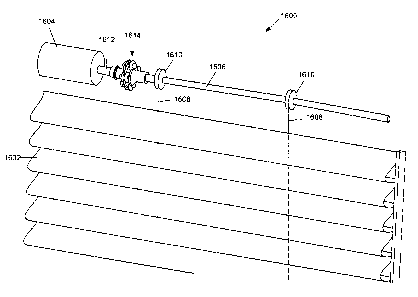
process may
include inserting elastic rings 202 into notches 228 of tube adapter 204 first
(as depicted in FIG.
3), and then inserting posts 214 into elastic rings 202. After elastic rings
202 are on posts 214
and tube adapter 204 is disposed between posts 214 and operatively engaged
with elastic rings
202, retainer 206 may be placed onto posts 214 to retain tube adapter 204 and
elastic rings 202
on posts 214.
- 23 -
CA 2993964 2018-02-05
[0071] Referring back to FIG. 2, each post 214 includes a first section 240
(one of which is
referenced in FIG. 2) have a circular cross-section and a second section 242
having a cross-
shaped cross-section (one of which is referenced in FIG. 2). When drive
coupling 110 is
assembled, each elastic ring 202 is disposed on first section 240 of the
corresponding post 214,
and retainer 206 is disposed on second sections 242 of posts 214. Second
sections 242 are
shaped to provide an interference fit with retainer 206. In other words,
retainer 206 may be
coupled to posts 214 by pressing retainer 206 onto posts 214. In other aspects
of the disclosure,
first section 240 and/or second section 242 may be shaped differently. For
example, the second
section 242 may be have a square-shaped cross-section. Additionally or
alternatively, in other
aspects of the disclosure, other chemical and/or mechanical fasteners may be
used to couple
retainer 206 and posts 214. For example, instead of using retainer 206, the
ends of posts 214
may include nubs (e.g., similar to nubs 1720 disclosed in connection with
first driver 1700 of
FIG. 17) to retain elastic rings 202 on posts 214.
[0072] FIG. 5 shows another perspective view of assembled drive coupling
110. In the
illustrated example of FIG. 5, mounting shaft 208 of driver 200 includes an
opening 500
(sometimes referred to as an output shaft opening) to receive motor output
shaft 108 of motor
104 (FIG. 1). In one aspect of the disclosure, driver 200 is coupled to motor
output shaft 108 via
an interference fit. In another aspect of the disclosure, driver 200 is
coupled to motor output
shaft 108 via a set screw (a screw extending through mounting shaft 208 into
motor output shaft
108). Additionally or alternatively, in another aspect of the disclosure,
other chemical and/or
mechanical fasteners may be used to couple driver 200 and motor output shaft
108.
[0073] In accordance with one aspect of this disclosure, the elastic rings
are implemented as
grommets. The elastic rings have an outer diameter and an inner diameter. In
accordance with
- 24 -
CA 2993964 2018-02-05
,
one aspect of this disclosure, each elastic ring includes a groove around an
edge or
circumferential surface of the elastic ring.
[0074] For example, FIG. 6A is a side view of one of elastic rings 202
and FIG. 6B is a top
or plan view of elastic ring 202. As illustrated in FIGS. 6A and 6B, elastic
ring 202 has a height
H (or thickness), an outer diameter D1, and an inner diameter D2 (which is the
diameter of
opening 230). In one aspect of the disclosure, height H is about 0.1875 inches
(in) (4.7625
millimeters (mm)) (e.g., 0.003in (0.076mm)) and outer diameter D1 is about
0.3437in
(8.7313mm) (e.g., 0.003in (0.076mm)). In other aspects of the disclosure,
height H and/or
outer diameter D1 may be larger or smaller. In one aspect of the disclosure,
the clearance or
difference between inner diameter D2 and a diameter of the respective post 214
(FIG. 2) is about
0.005in (0.127mm) (e.g., 0.003in (0.076mm)). For example, inner diameter D2
may be about
0.125in (3.175mm) and the diameter of post 214 may be about 0.119in (3.023mm)
0.003in
(0.076mm). This clearance results in the most noise reduction while still
enabling easy assembly
of elastic rings 202 on posts 214. In other aspects of this disclosure, inner
diameter D2 of elastic
ring 202 and/or the diameter of the respective post 214 may be larger or
smaller. For example,
depending on the durometer of elastic rings 202, the tolerance or clearance
between posts 214
and elastic rings 202 may be larger or smaller. In some aspects of this
disclosure, reducing a
contact area between posts 214 and the inner surfaces of the respective
elastic rings 202 reduces
potential noise generated by vibrations between the components. Thus, the
dimensions and
clearances can be changed based on difference in size, the materials used,
and/or a design
configuration that that minimizes surface area contact. In other aspects of
the disclosure, the
dimensions of elastic rings 202 and/or posts 214 may be selected such that the
contact area is not
- 25 -
CA 2993964 2018-02-05
minimized (e.g., to couple elastic rings 202 tightly to posts 214 such that a
relatively large
contact area is produced).
[0075] As illustrated in FIG. 6A, groove 232 has a width W and a depth R.
In one aspect of
the disclosure, depth R may be about 0.047in (1.1938mm) (e.g., 0.003in
(0.076mm)). In other
aspects of the disclosure, depth R may be larger or smaller. In one aspect of
this disclosure, the
clearance or difference between width W of groove 232 and a width of web 236
(FIG. 2) is about
0.005in (or 0.127mm) (e.g., 0.003in (0.076mm)). For example, width W may be
about
0.0625in (1.5875mm) and the width of web 236 may be about 0.087in (2.21mm)
(e.g., 0.003in
(0.076mm)). This clearance results in minimal noise caused from vibration
between the parts
and components. In other aspects of this disclosure, the dimensions of width W
and/or the width
of web 236 may be larger or smaller.
[0076] FIG. 7 shows an end view of drive coupling 110 and roller tube 106.
In the illustrated
example, roller tube 106 includes an inner surface 700 having extensions 702
that extend radially
inward from inner surface 700. Extensions 702 are spaced apart to match the
arrangement of
slots 226 on arms 220. As such, when drive coupling 110 is inserted into
roller tube 106,
extensions 702 are inserted into slots 226 in arms 220. Thus, when tube
adapter 204 is rotated,
roller tube 106 is rotated.
[0077] While in the illustrated example of FIG. 7 roller tube 106 includes
four extensions
702 (one for each of slots 226), in other aspects of the disclosure, roller
tube 106 may include
more or fewer extensions. Likewise, tube adapter 204 may include more or fewer
slots 226. For
example, only one slot may be provided on one arm 220, and only one extension
may be
provided on inner surface 700 of roller tube 106. In other aspects of the
disclosure, slots 226 and
extensions 702 are reversed. For example, arms 220 may include extensions that
extend from
- 26 -
CA 2993964 2018-02-05
arms 220, and inner surface of roller tube 106 may include slots to receive
the extensions on
arms 220.
[0078] In one aspect of the disclosure, tube adapter 204 may be
interchanged with another
tube adapter having a different design corresponding to a different roller
tube. As such, drive
coupling 110 can be used to drive a variety of different roller tubes. For
example, FIG. 8 shows
an end view of a second roller tube 800 and a second tube adapter 802 carried
by driver 200. In
the illustrated example, second roller tube 800 includes an inner surface 804
with two sections of
teeth 806 extending inward from inner surface 804. Tube adapter 802 includes
four arms 808,
similar to tube adapter 204 of FIG. 2. Two of arms 808 include teeth 810 to
mate with teeth 806
on second roller tube 800. In another aspect of this disclosure, second roller
tube 800 may
include more or fewer sections of teeth and second tube adapter 802 may
include more or fewer
matching sections of teeth. In another aspect of this disclosure, other shaped
features may be
used instead of teeth and/or the features may be spaced differently. Further,
in one aspect of this
disclosure, second tube adapter 802 may have longer or shorter arms than tube
adapter 204 of
FIG. 2. As such, drive coupling 110 can be used to drive roller tubes having
larger or smaller
diameters than roller tube 106. Thus, drive coupling 110 can be easily adapted
to interact with a
variety of different roller tubes.
[0079] In accordance with one aspect of this disclosure, one or more of the
arms of the tube
adapter may include one or more fingers extending radially outward from the
arm(s) and engage
the inner surface of the roller tube. The finger(s) increase the contact area
between the tube
adapter and the roller tube to further help reduce potential vibrations (and,
thus, noise) between
the drive coupling and the roller tube. The finger(s) may be flexible and may
help maintain the
tube adapter centered within the roller tube. The finger(s) may also help take
up any radial
- 27 -
CA 2993964 2018-02-05
tolerance or excess space between the ends of the arms of the tube adapter and
the inner surface
of the roller tube.
[0080] FIG. 9 illustrates another tube adapter 900 that may be implemented
with drive
coupling 110. Tube adapter 900 is similar to tube adapter 204 (FIGS. 2 and 7)
and includes a
central portion 902, arms 904 that extend outwardly from central portion 902,
curved notches
906 (to receive vibration-absorbers) formed between adjacent arms 904, and
mating features,
implemented in this example as slots 908, formed in ends 910 of arms 904 to
mate with
corresponding features on an inner surface of a rotating member, such as a
roller tube (e.g., roller
tube 106 of FIGS. 1 and 7). Additionally, tube adapter 900 includes fingers
912 (two of which
are referenced in FIG. 9) that extend outward from ends 910 of arms 904 (in a
direction along a
central axis of tube adapter 900) and radially outward (e.g., upward) from
ends 910 of arms 904,
as can be seen in the callout in FIG. 9. Fingers 912 are flexible and biased
outwardly to maintain
contact with an inner surface of the roller tube to remove any clearance
between the tube adapter
and the roller tube (which may be a potential source of noise generation). For
example, if tube
adapter 900 is inserted into a roller tube, such as roller tube 106 of FIG. 7,
fingers 912 are biased
against inner surface 700 of roller tube 106. Fingers 912 increase the contact
point with the
roller tube 106 and take up any radial tolerance or excess clearance between
tube adapter 900
and roller tube 106. Therefore, if there is a gap between ends 910 of arms 904
and inner surface
700 of the roller tube 106 (e.g., due to lower manufacturing tolerances),
fingers 912 help to keep
tube adapter 900 (and, thus, drive coupling 110) centered within the roller
tube 106 and prevent
movement of roller tube 106 and/or tube adapter 900 in the radial directions
(which may
otherwise cause vibration and, thus, noise). In some aspects of this
disclosure, fingers 912 are
not subject to any torsional forces when tube adapter 900 rotates roller tube
106. In other words,
- 28 -
CA 2993964 2018-02-05
=
fingers 912 are not intended to engage extensions 702 on roller tube 106.
Instead, fingers 912
help maintain tube adapter 900 centered, so that sufficient contact can be
made between the inner
surfaces of slots 908 in arms 904 and extensions 702 on roller tube 106 to
transfer rotational
motion from tube adapter 900 to roller tube 106 when tube adapter 900 is
rotated. In the
illustrated example, fingers 912 have a relatively small, negative rake angle
to prevent fingers
912 from catching or snagging on inner surface 700 of roller tube 106 (e.g.,
during insertion
and/or removal of the corresponding drive coupling from roller tube 106). In
the illustrated
example of FIG. 9, two fingers 912 are implemented on each arm 904 and are
disposed on either
side of the corresponding slot 908 on each arm 904. In other examples, more or
fewer fingers
912 may be implemented and/or fingers 912 may be arranged in other
configurations.
[0081] FIG. 10 illustrates another tube adapter 1000 that may be
implemented with drive
coupling 110. Similar to tube adapter 204 (FIG. 2), tube adapter 1000 includes
a central portion
1002, arms 1004 that extend outwardly from central portion 1002, and curved
notches 1006 (to
receive vibration-absorbers) formed between adjacent arms 1004. In the
illustrated example of
FIG. 10, arms 1004 are relatively straight (compared to arms 220 of tube
adapter 204) and extend
outwardly further than arms 220 of tube adapter 204. In the illustrated
example, ends 1008 of
arms 1004 are slightly enlarged (e.g., tapered outward) and configured to be
inserted into
corresponding slots or grooves formed on an inner surface of a roller tube.
Additionally, in the
illustrated example of FIG. 10, tube adapter 1000 includes fingers 1010 that
extend outwardly
from ends 1008 of arms 1004 (in a direction along a central axis of tube
adapter 1000) and
radially outward (e.g., upward) from ends 1008 of arms 1004. Similar to
fingers 912 of tube
adapter 900 (FIG. 9), fingers 1010 increase the contact surface of tube
adapter 1000 with a roller
tube and help center tube adapter 1000 within the roller tube, which reduces
movement and, thus,
- 29 -
CA 2993964 2018-02-05
potential vibrations between tube adapter 1000 and the corresponding roller
tube. In other
examples, more or fewer fingers 1010 may be implemented and/or fingers 1010
may be disposed
in other locations.
[0082] FIG. 11 illustrates another tube adapter 1100 that may be
implemented with drive
coupling 110. Similar to tube adapter 204 (FIGS. 2), tube adapter 1100
includes a central
portion 1102, arms 1104 that extend outwardly from central portion 1102, and
curved notches
1106 (to receive vibration-absorbers) formed between adjacent arms 1104. In
the illustrated
example of FIG. 11, arms 1104 are shaped similar to arms 220 of tube adapter
204. In the
illustrated example, ends 1108 of arms 1104 are relatively wide and configured
to be inserted
into corresponding slots or grooves formed on an inner surface of a roller
tube. Additionally, in
the illustrated example of FIG. 11, tube adapter 1100 includes fingers 1110
that extend
outwardly from ends 1108 of arms 1104 (in a direction along a central axis of
tube adapter 1100)
and radially outward (e.g., upward) from ends 1108 of arms 1104. Similar to
fingers 912 of tube
adapter 900 (FIG. 9), fingers 1110 increase the contact surface of tube
adapter 1100 with a roller
tube and help center tube adapter 1100 within the roller tube, which reduces
movement and, thus,
potential vibrations between tube adapter 1100 and the corresponding roller
tube. In other
examples, more or fewer fingers 1110 may be implemented and/or fingers 1110
may be disposed
in other locations.
[0083] While in the illustrated example of FIGS. 1-11, tube adapters 204,
900, 1000, 1100
are configured to be disposed between posts 214 and elastic rings 202 with
arms extending
outwardly, beyond elastic rings 202 to engage roller tube 106, in other
examples, a tube adapter
may be disposed outside posts 214 and elastic rings 202. For example, a tube
adapter in the form
of a cylindrical sleeve may be disposed around elastic rings 202. An inner
surface of the
- 30 -
CA 2993964 2018-02-05
cylindrical sleeve may include grooves to receive respective ones of elastic
rings 202. An outer
surface of the cylindrical sleeve may have one or more features (e.g., similar
to slots 226 on arms
220 of tube adapter 204) to mate with corresponding features on inner surface
700 of roller tube
106. Rotational motion may be similarly transferred to the cylindrical sleeve
by rotating driver
200, which interfaces with the cylindrical sleeve via the elastic rings 202.
[0084] As mentioned above, driver 200 (FIG. 2) includes opening 500 (FIG.
5) to receive
motor output shaft 108 (FIG. 1). Opening 500 should be configured to contact
motor output
shaft 108 along a sufficient length or in multiple contact locations/points to
keep driver 200
centered with respect to motor output shaft 108. One example manufacturing
process that may
be used to construct driver 200 is die casting. Die casting is a relatively
fast and inexpensive
process for making metallic parts. Die casting includes forcing molten metal
into a mold cavity
formed by two or more dies. After the metal hardens, the dies are separated
and the resulting
part is ejected. To die cast driver 200, for example, opening 500 may be
formed by a pin that is
disposed in the mold cavity. When, the pin is removed after the metal hardens,
the resulting void
forms opening 500 through mounting shaft 208. The pin is tapered at a draft
angle so that the pin
can be removed after the mold is opened. However, using a single tapered pin
may result in a
tapered or angled opening that may not desirable because only minimal contact
would be
achieved between motor output shaft 108 and the inside of opening 500. In
other words, only the
smallest diameter portion of the tapered opening may form the contact location
with the motor
output shaft. With such a small contact location, driver 200 may become
misaligned on the
motor output shaft. Further, driver 200 may wobble or vibrate on the motor
output shaft, which
generates noise.
- 31 -
CA 2993964 2018-02-05
[0085] FIG. 12 illustrates an example driver 1200 that may be manufactured
via a die casting
process and is designed to overcome the above issues. In particular, driver
1200 includes an
opening for a motor output shaft that is configured to have better alignment
with the motor
output shaft and form a relatively tight fit with the motor output shaft and,
thus, results in
reduced vibrations (and potential noise) between driver 1200 and the motor
output shaft. Driver
1200 may be used as an alternative to driver 200 or the example manufacturing
process
described below may be similarly performed on driver 200 (or any other drivers
disclosed
herein) to address the above challenges. Driver 1200 is similar to driver 200
and includes a
mounting shaft 1202, a plate 1204, and a set of posts 1206 extending from
plate 1204. Mounting
shaft 1202 includes an opening 1208 (sometimes referred to as an output shaft
opening) to
receive a motor output shaft, such as motor output shaft 108 (FIG. 1). Opening
1208 extends
along a rotational axis 1210 (e.g., a central or longitudinal axis) of driver
1200. In the illustrated
example, mounting shaft 1202 is formed with a transverse opening 1212 that
extends through
mounting shaft 1202 in a direction that is perpendicular to opening 1208
(e.g., transverse
opening 1212 extends along an axis that is perpendicular to rotational axis
1210). Transverse
opening 1212 enables multiple pins to be used during the die casting process
to form a more
desirably shaped opening, as discussed in further detail below in conjunction
with FIG. 14. In
the illustrated example, opening 1208 has a shape that is rectangular with
curved sides. The
shape of opening 1208 is configured to substantially match the shape of the
corresponding motor
output shaft. In other examples, the shape of opening 1208 may be different
(e.g., a star, a
triangle, etc.).
[0086] FIG. 13 is a cross-sectional view of driver 1200 taken along line A-
A of FIG. 12. As
shown in the illustrated example, transverse opening 1212 extends through
mounting shaft 1202
- 32 -
CA 2993964 2018-02-05
,
and intersects opening 1208. In the illustrated example, opening 1208 is
divided into a first
channel 1300 on one side of transverse opening 1212 (the left side in FIG. 13)
and a second
channel 1302 on the other side of transverse opening 1212 (the right side in
FIG. 13). First and
second channels 1300, 1302 are slightly tapered inward (as discussed in
further detail in
conjunction with FIG. 14). The smallest diameter portion of first channel 1300
forms a first
contact location 1304 and the smallest diameter portion of second channel 1302
forms a second
contact location 1306. First and second contact locations 1304, 1306 are
configured to engage a
motor output shaft (as discussed in further detail in conjunction with FIG.
15).
[0087] FIG. 14 shows an example configuration of the pins that may be
used during the die
casting process to form opening 1208 and transverse opening 1212 in driver
1200. As
illustrated, when forming driver 1200, a first pin 1400 extends into mounting
shaft 1202 from
one side (the left side in FIG. 14) and a second pin 1402 extends into
mounting shaft 1202 from
the opposite side (the right side in FIG. 14), which form first and second
channels 1300, 1302
(FIG. 13). Additionally, a third pin 1404 extends into mounting shaft 1202 in
a transverse
direction (from the top side in FIG. 14) and a fourth pin 1406 extends into
mounting shaft 1202
from an opposite transverse direction (from the bottom side in FIG. 14), which
form transverse
opening 1212. As mentioned above, pins 1400-1406 are tapered (at a draft
angle) to enable
removal of pins 1400-1406 after the driver mold hardens. As such, the
resulting openings or
channels in mounting shaft 1202 are tapered or angled. Pins 1400-1406 may have
any shaped
cross-section (e.g., a conical cross-section, a square shaped cross-section,
etc.) to produce an
opening that matches the corresponding motor output shaft.
[0088] FIG. 15 illustrates motor output shaft 108 inserted into
opening 1208 of mounting
shaft 1202. First and second contact locations 1304, 1306 are the smallest
diameter portions of
-33 -
CA 2993964 2018-02-05
opening 1208 formed by first and second pins 1400, 1402 (FIG. 14) during the
die casting
process. These contact locations 1304, 1306 are spaced apart from each other
(on opposite sides
of transverse opening 1212). In other words, use of pins 1404, 1406 creates
the two spaced apart
contact locations 1304, 1306. The contact locations 1304, 1306 are configured
to engage motor
output shaft 108 at two spaced apart locations (e.g., near two opposite ends
of motor output shaft
108). As a result, driver 1200 remains substantially aligned with and secured
on motor output
shaft 108, as compared to a driver with a single tapered opening having only
one contact point,
which results in reduced vibrations and, thus, less potential noise from
vibrations. As disclosed
above, in some aspects of this disclosure, mounting shaft 1202 may be coupled
to motor output
shaft 108 via an interference fit. Further, using the four pin configuration
results in a longer
opening (with spaced apart contact points) that enables motor output shaft 108
to penetrate
deeper into driver 1200, thereby providing better contact and alignment to
reduce potential
vibrations between driver 1200 and motor output shaft 108. Thus, this
configuration results in
better tolerances, less rattling and/or vibrations and, thus, less potential
noise from vibrations.
Also, with the four pin configuration, first and second pins 1400, 1402 can
have relatively larger
draft angles, which is not as readily achievable with a single pin. In some
instance, having larger
draft angles facilitates removal of the pins. Further, in some instance,
transverse opening 1212
may be used when assembly driver 1200 on a motor output shaft to verify and
ensure the motor
output shaft is inserted properly into opening 1208. For example, a
manufacturing personnel
may look into transverse opening 1212 when sliding driver 1200 onto a motor
output shaft to
ensure the motor output shaft is inserted properly into opening 1208. Further,
with the four pin
configuration, the dimension(s) (e.g., lengths and widths) of pins 1400-1406
can be changed to
create longer or shorter openings for accommodating different length motor
output shafts.
- 34 -
CA 2993964 2018-02-05
[0089] In other aspects of this disclose, a driver, such as driver 200
(FIG. 2) or driver 1200
(FIG. 12) may be die cast using a pin that extends all the way through the
drive to create an
opening for the motor output shaft. In some such examples, a pin with a
relatively small draft
angle (if any) may be used to produce a relative straight opening. In still
other aspects of this
disclosure, a driver, such as driver 200 (FIG. 2) or driver 1200 (FIG. 12),
may be die cast without
an opening for the motor output shaft. Instead, the mounting shaft may be
molded as a
substantially solid part or component. Then, a secondary process, such as
drilling and broaching,
may be used to form the opening through the mounting shaft. In such an
example, a
substantially straight opening may be formed in the mounting shaft that can
maintain sufficient
contact with the motor output shaft to remain aligned and secured to motor
output shaft.
[0090] As disclosed above, in other aspects of this disclosure, example
drive couplings may
be used between motors and rotating members having other configurations where
the motor is
not concentric with the rotating member, such as a motor and a lift rod that
are configured or
arranged in line or end-to-end. For example, an example drive coupling may be
used to couple
an output shaft of a motor to a rotating member, such as a lift rod, that is
axially aligned (or
substantially axially aligned) with the output shaft of the motor. The example
drive coupling
may be used reduce potentially noise that would otherwise be generated by the
connection
between the motor and the rotating member.
[0091] For example, FIG. 16 illustrates another example of an architectural
covering 1600
having a covering 1602. Similar to architectural covering 100 disclosed above,
architectural
covering 1600 may be used to cover an architectural structure, such as a wall,
and/or an
architectural opening, such as a window, a door, a sky light, an archway, etc.
In the illustrated
example of FIG. 16, architectural covering 1600 includes a motor 1604 and a
rotating member,
- 35 -
CA 2993964 2018-02-05
,
implemented as a lift rod 1606. In other examples, other types of rotating
members may be
implemented. For the sake of convenience, the example of the architectural
covering 1600 is
described in connection with lift rod 1606. However, it is understood that
lift rod 1606 is non-
limiting, and other types of rotating members may be used in addition to or as
an alternative to
lift rod 1606. Lift rod 1606 may be rotated to wind or unwind one or more lift
cords 1608 to
extend or retract covering 1602. In particular, each lift cord 1608 is coupled
to a respective
spool 1610 (e.g., a reel). When lift rod 1606 is rotated in one direction,
lift cords 1608 are
wrapped around spools 1610, which causes cover 1602 to retract (e.g., raise or
otherwise uncover
an architectural structure and/or opening), and when lift rod 1606 is rotated
in the opposite
direction, lift cords 1608 are unwound from spools 1610, which causes cover
1602 to extend
(e.g., lower or otherwise cover the architectural structure and/or opening).
Motor 1604 operates
to rotate lift rod 1606 in one direction or the other direction depending on
the desired operation.
Motor 1604 has a motor output shaft 1612. Similar to motor 104 of FIG. 1,
motor 1604 may be
powered by any combination of internal and/or external power line connections,
power from a
wall outlet, battery(ies), fuel cells, solar panels, wind powered generators,
and/or any other
power source.
[0092] In accordance with one aspect of this disclosure, an example drive
coupling 1614 is
used to transfer rotational motion from motor output shaft 1612 to a rotating
member, such as lift
rod 1606. Drive coupling 1614 greatly reduces noise that would otherwise be
generated by the
connection between motor 1604 and lift rod 1606. In particular, drive coupling
1614 is coupled
to and rotates with motor output shaft 1612. Additionally, drive coupling 1614
is coupled to lift
rod 1606. As such, when motor 1604 rotates motor output shaft 1612, drive
coupling 1614
transfers the rotational motion to lift rod 1606. As illustrated in FIG. 16,
lift rod 1606 is
- 36 -
CA 2993964 2018-02-05
substantially axially aligned with motor output shaft 1612 and, thus, drive
coupling 1614
transfers rotational motion from motor output shaft 1612, upstream of drive
coupling 1614, to lift
rod 1606, downstream of drive coupling 1614.
[0093] In accordance with one aspect of this disclosure, the drive coupling
includes one or
more vibration-absorbers that are used to reduce vibration between the parts
of the architectural
covering. For example, the drive coupling may include a driver, referred to as
a first driver, that
connects to the output shaft of the motor and a driven member, referred to a
second driver, that
connects to the lift rod. The first driver rotates the second driver to rotate
the lift rod. In
accordance with one aspect of this disclosure, vibration-absorbers are
utilized between the first
driver and the second driver to reduce vibration and, thus, reduce potential
noise in the
architectural covering. For example, the first driver may include a first set
of mounting
structures, such as posts, extending outwardly from a plate in a direction
that is parallel to and
offset from a rotational axis of the first driver, and the second driver may
include a second set of
mounting structures, such as posts, extending outwardly from another plate in
a direction that is
parallel to and offset from a rotational axis of the second driver. In
accordance with some
aspects of the disclosure, the first and second drivers are positioned such
that the first set of posts
extend toward the second driver and the second set of posts extend toward the
first driver. To
transfer rotational motion from the first set of posts to the second set of
posts, the drive coupling
includes an intermediate structure, such as a hub, coupled with a plurality of
vibration-absorbers.
In accordance with one aspect of the disclosure, the hub is disposed between
the first set of posts
and the second set of posts. As the first driver rotates, the first set of
posts rotate the hub via the
vibration-absorbers and, thus, rotate the second set of posts with the
vibration-absorbers and,
thus, rotate the second driver. In accordance with one aspect of the
disclosure, the vibration-
- 37 -
CA 2993964 2018-02-05
absorbers are located between the posts and the hub. As such, the second
driver is operatively
engaged with the vibration-absorbers on the posts of the first driver (e.g.,
via the vibration-
absorbers on the posts of the second driver and the hub). In accordance with
some aspects of the
disclosure, the second driver may be positioned such that the second set of
posts extend in the
same direction as the first set of posts of the first driver. In such an
example, the second driver
may include a central mounting shaft that extends through a central opening
the hub and couples
to the lift rod. In accordance with one aspect of the disclosure, the
vibration-absorbers may be
embodied as elastic rings. For example, an elastic ring may be disposed on
each post, and the
hub is engaged by the elastic rings. Thus, the second driver is indirectly
coupled to the first
driver by the elastic rings (and the hub). In one aspect of the disclosure,
the elastic rings are
implemented as grommets. The interface between the first driver, the vibration-
absorbers, the
hub, and the second driver results in decreased vibration, which greatly
reduces and/or eliminates
noise that would otherwise be generated by a traditional connection.
[0094]
For example, FIG. 17 is an exploded view of an example of an embodiment of a
drive
coupling. In the illustrated example, drive coupling 1614 includes a driver
1700, referred to as
first driver 1700, a set of elastic rings 1702, a hub 1704, and a second
driver 1706 (e.g., a driven
member, a lift cord interface). First driver 1700 includes a mounting shaft
1708 that is
configured to be coupled to motor output shaft 1712 of motor 1604 (FIG. 16).
In one aspect of
this disclosure, mounting shaft 1708 includes an opening 1710 to receive motor
output shaft
1612. In one aspect of the disclosure, first driver 1700 is coupled to motor
output shaft 1712 via
an interference fit. In another aspect of the disclosure, first driver 1700 is
coupled to motor
output shaft 1612 via a set screw (a screw extending through mounting shaft
1708 into motor
output shaft 1612). Additionally or alternatively, in another aspect of the
disclosure, other
- 38 -
CA 2993964 2018-02-05
chemical and/or mechanical fasteners may be used to couple first driver 1700
and motor output
shaft 1612. When coupled to motor output shaft 1612, motor 1604 rotates first
driver 1700 about
a first rotational axis 1712 (e.g., a central or longitudinal axis of first
driver 1700). In one aspect
of this disclosure, first rotational axis 1712 is substantially aligned with
the rotational axis of
motor output shaft 1612 of motor 1604.
[0095] In the illustrated example of FIG. 17, first driver 1700 includes a
plate 1714 coupled
to mounting shaft 1708. Plate 1714 is oriented perpendicular to first
rotational axis 1712. First
driver 1700 includes a set of posts 1716 that are coupled to and extend from a
face 1718 of plate
1714. In other aspects of this disclosure, first driver 1700 may include more
(e.g., three, four,
etc.) or fewer (e.g., one) posts. Posts 1716 are parallel to and offset from
first rotational axis
1712. Each post 1716 may include a ball or nub 1720 at the distal end of the
respective post
1716 to restrict the respective elastic rings 1702 from sliding off, as
disclosed in further detail
herein. In one aspect of this disclosure, first driver 1700 is constructed as
a substantially unitary
part or component. For example, first driver 1700 may be molded as a single
part or component
and/or machined from a single piece of material. In another aspect of this
disclosure, first driver
1700 may be constructed of multiple parts or components that are coupled
together (e.g., posts
1716 may be welded to plate 1714, plate 1714 may be welded to mounting shaft
1708, etc.).
[0096] In the illustrated example, second driver 1706 includes a mounting
shaft 1722 that is
configured to be coupled to an end of a rotating member such as lift rod 1606
(FIG. 16). In one
aspect of this disclosure, second driver 1706 includes an opening to receive
lift rod 1606, as
disclosed in further detail in connection with FIG. 20. Similar to first
driver 1700, second driver
1706 includes a plate 1724 and a second set of posts 1726 with nubs 1728
extending from a face
1730 of plate 1724. Second driver 1706 is rotatable about a second rotational
axis 1731, which
- 39 -
CA 2993964 2018-02-05
,
,
is substantially aligned with the rotational axis of lift rod 1606. In one
aspect of the disclosure,
second rotational axis 1731 is substantially aligned with first rotational
axis 1712. In other
aspects of this disclosure, as discussed in further detail in connection with
FIGS. 21A and 21B,
second rotational axis 1731 may not be aligned with first rotational axis
1712.
[0097] To transfer rotational motion between first driver 1700 and
second driver 1706, hub
1704 is disposed between first driver 1700 and second driver 1706. In the
illustrated example,
hub 1704 is a plate having four notches 1732 in an outer edge 1734 of hub
1704. When drive
coupling 1614 is assembled, hub 1704 is disposed between posts 1716 of first
driver 1700 and
posts 1726 of second driver 1706. Therefore, first driver 1700 rotates hub
1704, which rotates
second driver 1706 to transfer rotational motion to lift rod 1606 (FIG. 16).
[0098] Similar to drive coupling 110 disclosed in connection with
FIGS. 1-8, one or more
parts for absorbing vibration are included in drive coupling 1614 to dampen
potential vibration
and, thus, reduce potential noise. The vibration-absorber(s) may be
constructed of a lower
durometer material (e.g., Shore A material such as nitrile rubber). The
vibration-absorber(s) may
be interposed in one or more locations between the relatively harder part(s)
of drive coupling
1614. For example, referring to FIG. 17, drive coupling 1614 includes elastic
rings 1702. In the
illustrated example, elastic rings 1702 are implemented as grommets. Each
elastic ring 1702
includes an opening 1736 (one of which is reference in FIG. 17) and a groove
1738 (one of
which is referenced in FIG. 17) formed around an outer edge of the respective
elastic ring 1702.
Elastic rings 1702 may be substantially the same as elastic rings 202
disclosed in detail above in
connection with FIG. 2. Thus, to avoid redundancy, a description of the type
of materials, the
function, and the sizes of the elastic rings 1702 is not repeated here.
Instead, the interested
- 40 -
CA 2993964 2018-02-05
reader is referred back to the discussion of FIGS. 2-8 for a full written
description of the elastic
rings.
[0099]
As illustrated in FIG. 18, elastic rings 1702 are configured to be inserted
into notches
1732 (FIG. 17) of hub 174. As such, outer edge 1734 of hub 1704 extends into
grooves 1738
(one of which is referenced in FIG. 18) of each elastic ring 1702. Further,
generally one elastic
ring 1702 is to be coupled to each of posts 1716 of first driver 1700 and
posts 1726 of second
driver 1706. In particular, posts 1716, 1726 are to be inserted into openings
1736 (one of which
is referenced in FIG. 18) of the respective elastic rings 1702. Thus, second
driver 1706 is
operatively engaged with the elastic rings 1702 on posts 1716 of the first
driver 1700 (via elastic
rings 1702 on posts 1726 of second driver 1706 and hub 1704). Nubs 1720, 1728
have a larger
diameter than openings 1736 of elastic rings 1702. As a result, once elastic
rings 1702 are on
posts 1716, 1726, nubs 1720, 1728 help to maintain elastic rings 1702 on posts
1716, 1726,
unless a sufficient force is applied in the axial direction to pull the
corresponding nub 1720, 1728
through opening 1736 of the corresponding elastic ring 1702. An example
process of assembling
drive coupling 1714 may include inserting posts 1716, 1726 into elastic rings
1702 (i.e., placing
elastic rings 1702 on posts 1716, 1726), and then placing hub 1704 between
posts 1716, 1726
such that elastic rings 1702 are inserted into notches 1732 of hub 1704.
Another example
assembly process may include inserting elastic rings 1702 into notches 1732 of
hub 1704 first (as
shown in FIG. 18), and then inserting posts 1716, 1726 into elastic rings
1702.
[00100] In accordance with one aspect of this disclosure, the clearance
between the inner
diameter of openings 1736 and a diameter of respective posts 1716, 1726 may be
about 0.005in
(0.127mm) (e.g., 0.003 in (0.076mm)), similar to the clearance disclosed
above in connection
with elastic rings 202 and posts 214 of FIG. 2. For example, the inner
diameter may be about
- 41 -
CA 2993964 2018-02-05
0.125in (3.175mm) and the diameter of posts 1716, 1726 may be about 0.119in
(3.023mm)
0.003in (0.076mm). In some instances, this clearance results in the most noise
reduction while
still enabling easy assembly of elastic rings 1702 on posts 1716, 1726. In
other aspects of this
disclosure, the inner diameter of elastic rings 1702 and/or the diameter of
the respective posts
1716, 1726 may be larger or smaller. In one aspect of this disclosure, the
clearance or difference
between the width of groove 1738 and a width of hub 1704 is about 0.005in
(0.127mm) (e.g.,
+0.003in (0.076mm)). For example, the width of groove 1738 may be about
0.0625in
(1.5875mm) and the width of hub 1704 may be about 0.087in (2.21mm) (e.g.,
0.003in
(0.076mm)). In some instances, this clearance results in minimal noise caused
from vibration
between the parts and components of the architectural covering 1600. In other
aspects of this
disclosure, the dimensions of the width of groove 1738 and/or the width of hub
1704 may be
larger or smaller.
1001011 In the illustrated example, first driver 1700 includes two posts 1716
and second driver
1706 includes two posts 1726. In other aspects of this disclosure, first
driver 1700 and/or second
driver 1706 may include more or fewer posts. For example, first driver 1700
and second driver
1706 may each include three posts. In such an example, hub 1704 may include
six notches, and
elastic rings may be disposed on each of the posts between the respective post
and hub 1704.
[00102] Assembled views of drive coupling 1614 are illustrated in FIGS. 19 and
20. In the
assembled state, posts 1716 of first driver 1700 extend outwardly beyond hub
1704 toward
second driver 1706, and posts 1726 of second driver 1706 extend outwardly
beyond hub 1704
toward first driver 1700 (e.g., in the opposite direction). As a result, hub
1704 is disposed
between posts 1716, 1726 and, thus, between first driver 1700 and second
driver 1706. In the
assembled state, elastic rings 1702 are disposed along a common plane. In some
aspects of this
- 42 -
CA 2993964 2018-02-05
disclosure, nubs 1720, 1728 on posts 1716, 1726 prevent elastic rings 1702
and, thus, hub 1704
from being removed from posts 1716, 1726 (unless a sufficient force is applied
in either direction
to pull the corresponding nub 1720, 1728 through opening 1736 of the
corresponding elastic ring
1702). In other aspects of this disclosure, no nubs may be used.
[00103] As illustrated in FIGS. 19 and 20, elastic rings 1702 are interposed
between first
driver 1700 and hub 1704, and between hub 1704 and second driver 1706, which
reduces or
eliminates contact between first driver 1700, hub 1704, and second driver
1706. Elastic rings
1702 absorb vibration that may otherwise cause acoustic waves (e.g., sound)
between first driver
1700 (e.g., the driving member) and second driver 1706 (e.g., the driven
member). In the
illustrated example of FIG. 20, mounting shaft 1722 of second driver 1706
includes an opening
2000 to receive lift rod 1606 (FIG. 16). In one aspect of the disclosure,
second driver 1706 is
coupled to lift rod 1606 via interference fit. Additionally or alternatively,
in another aspect of
the disclosure, other chemical and/or mechanical fasteners may be used to
couple second driver
1706 and lift rod 1606.
[00104] In some aspects of this disclosure, the drive coupling may be used to
enable transfer
of rotational motion even if the output shaft of the motor and rotating member
(e.g., a lift rod)
are misaligned. For example, as illustrated in FIG. 21A, if second driver 1706
is angled with
respect to hub 1704 and and/or to first driver 1700, desired operation and
transference of rotation
are not impeded with the desired noise reduction of other embodiments
disclosed herein. In the
illustrated example of FIG. 21A, second driver 1706 has been rotated or tilted
about an axis
extending into the figure through posts 1726. In particular, second driver
1706 is angled with
respect to hub 1704 (at angle a) angled with respect to first driver 1700 (at
angle 0). Elastic rings
1702 (one of which is referenced in FIG. 21) compress or deform to enable
posts 1726 of second
- 43 -
CA 2993964 2018-02-05
,
driver 1706 to tilt with respective to openings 1736 (FIG. 17) of elastic
rings 1702 and, thus,
with respect to hub 1704 and/or first driver 1700. As such, second rotational
axis 1731 of second
driver 1706 (and, thus, lift rod 1606 (FIG. 16)) is not aligned with
rotational axis 1712 of first
driver 1700, but the desired transference of rotational motion is still
achieved.
[00105] While second driver 1706 is illustrated as tilted about an axis
(e.g., a first degree of
freedom) extending into the figure through posts 1726 in FIG. 21, second
driver 1706 may
additionally or alternatively be tilted about another axis (e.g., a second
degree of freedom) as
illustrated in FIG. 21. FIG. 21 illustrates drive coupling 1614 rotated 90
about first rotational
axis 1712, as compared to FIG. 21, and without second driver 1706 being tilted
about the axis in
FIG. 21. In FIG. 21, second driver 1706 is angled with respect to first driver
1700 about an axis
that extends into the figure through posts 1716 and is perpendicular to the
axis about which
second driver 1706 is tilted in FIG. 21A. In the illustrated example of FIG.
21B, hub 1704 is
angled with respect to first driver 1700 (at angle 13), and second driver 1706
is angled with
respect to first driver 1700 (at angle (p). Elastic rings 1702 (one of which
is referenced in FIG.
21B) compress or deform to enable posts 1716 of first driver 1700 to tilt with
respective to
openings 1736 (FIG. 17) of elastic rings 1702. Therefore, second rotational
axis 1731 of second
driver 1706 (and, thus, the rotating member (such as lift rod 1606 (FIG. 16)))
is not aligned with
first rotational axis 1712 of first driver 1700. Thus, second driver 1706 may
be rotated or tilted
about one or both of these axes (or vice versa). In other words, first and
second drivers 1700,
1706 are movable about two degrees of freedom relative to each other, which
enables first
rotational axis 1712 and second rotational axis 1731 to remain in relatively
fixed directions while
first and second drivers 1700, 1706 rotate. As such, drive coupling 1614
enables motor output
- 44 -
CA 2993964 2018-02-05
,
shaft 1612 (FIG. 16) to transfer rotational motion to the rotating member even
if motor output
shaft 1612 and the rotating member are not axially aligned.
[00106] Further, in some aspects of the disclosure, the drive coupling may be
used to enable
transfer of rotational motion if the output shaft of the motor and the
rotating member (e.g., a lift
rod) are parallel to but offset from each other. For example, as illustrated
in FIG. 22A, second
driver 1706 has been moved relative to first driver 1700 such that rotational
axis 1712 of first
driver 1700 and rotational axis 1731 of second driver 1706 are parallel to but
offset from each
other. In other words, first driver 1700 and/or second driver 1706 can be
shifted out of axial
alignment (e.g., sideways) and still transfer rotational motion, which enables
motor output shaft
1612 (FIG. 16) to transfer rotational motion to the rotating member even if
motor output shaft
1612 and the rotating member are not axially aligned. In FIG. 22A, hub 1704
has been removed
for clarity. FIG. 22B shows a plan view of the hub 1704. As illustrated, posts
1716, 1726
(represented by crosses) of first and second drivers 1700, 1706 (FIG. 22A) and
the associated
elastic rings (shown in dashed lines) can move within the respective notches
1732 in hub 1704,
thereby enabling hub 1704 to shift (up, down, left, or right in FIG. 22B). For
example, if first
driver 1700 is moved upward in FIG. 22B, posts 1716 of first driver 1700 move
hub 1704
upward, which causes posts 1726 of second driver 1706 to shift in the
respective notches 1732.
Likewise, if second driver 1706 is moved left in FIG. 22B, for example, posts
1726 of second
driver 1706 move hub 1704 left, which causes posts 1716 of first driver 1700
to shift in the
respective notches. Thus, the rotational axes of first and second driver 1700,
1706 (and, thus,
motor output shaft 1612 and the rotating member) may be offset from each
other. In some
aspects of this disclosure, posts 1716, 1726 (and, thus, the associated
elastic rings) can shift
about 0.020 inches in the respective notches 1732. In others aspects of this
disclosure, posts
- 45 -
CA 2993964 2018-02-05
1716, 1726 can shift more or less. For example, notches 1732 may be slotted
longer or shorter to
enable different amounts of travel.
[00107] While in drive coupling 1614 of FIGS. 16-22B first driver 1700 and
second driver
1706 are on opposite sides of hub 1704 (e.g., in an opposing arrangement), in
other aspects of
this disclosure, a drive coupling may include two drivers that are disposed on
the same side of a
hub. For example, FIGS. 23A and 23B illustrate another example drive coupling
2300 that may
be used with an architectural covering, such as architectural covering 1600
(FIG. 16), to transfer
rotational motion from a motor output shaft, such as motor output shaft 1612
(FIG. 16), to a
rotating member, such as lift rod 1606 (FIG. 16). In some examples, the
arrangement of parts of
drive coupling 2300 results in a shorter assembly time. Further, as shown in
the side view of
FIG. 23B, drive coupling 2300 has a shorter length (between an end of mounting
shaft 2310 and
an end of central mounting shaft 2320) and, thus, is more compact and can be
used in smaller
spaces (e.g., in a smaller gap between a motor output shaft and a lift rod).
[00108] FIG. 23A illustrates an exploded view of drive coupling 2300 and FIG.
23B
illustrates an assembled side view of drive coupling 2300. Drive coupling 2300
includes a driver
2302, referred to as first driver 2302, a set of elastic rings 2304, a hub
2306, and a second driver
2308 (e.g., a driven member, a lift cord interface). First driver 2302
includes a mounting shaft
2310, a plate 2312, and a first set of posts 2314 extending from plate 2312.
First driver 2302,
elastic rings 2304, and hub 2306 are substantially the same as first driver
1700, elastic rings
1702, and hub 1704 of drive coupling 1614 shown in FIGS. 16-22B. Thus, to
avoid redundancy,
a description of these structures and the associated functions are not
repeated herein. Instead, the
interested reader is referred back to the discussion of FIGS. 16-22B for a
full written description
of these structures and functions.
- 46 -
CA 2993964 2018-02-05
1001091 As illustrated in FIGS. 23A and 23B, second driver 2308 includes a
plate 2316 and a
second set of posts 2318 extending from plate 2316. In the illustrated
example, second driver
2308 is positioned such that posts 2318 extend in a same direction as posts
2314 of first driver
2302. When assembled, as shown in FIG. 23B, plate 2316 of second driver 2308
is disposed
between plate 2312 of first driver 2302 and hub 2306. Posts 2314, 2318 extend
through
respective ones of elastic rings 2304, which engage hub 2306, similar to drive
coupling 1614
disclosed above, to dampen vibration and, thus, reduce potential noise. As
shown in FIG. 23A
and 23B, second driver 2308 also includes a central mounting shaft 2320 that
extends from plate
2316 of second driver 2308 in the same direction as posts 2318. When drive
coupling 2300 is
assembled, central mounting shaft 2320 extends through a central opening 2322
(FIG. 23A) in
hub 2306. As shown in FIG. 23A, central mounting shaft 2320 includes an
opening 2324 to
receive a lift rod, similar to opening 2000 of second driver 1706 shown in
FIG. 20. Thus, the
arrangement of first driver 2302, vibration absorbers 2304, hub 2308, and
second driver 2308
enables a lift rod to be rotated with a motor output shaft. In the illustrated
example of FIG. 23A,
opening 2324 is V-shaped to receive a corresponding V-shaped end on a lift
rod. In other
examples, opening 2324 may be shaped differently. In some aspects of this
disclosure, central
opening 2322 is larger than the diameter of central mounting shaft 2320 to
enable central
mounting shaft 2320 (and, thus, second driver 2308) to move laterally. As
disclosed in
connection with FIGS. 21A-21B, the interaction between the posts, the elastic
rings, and the hub
enable first and second drivers 2302, 2308 to transfer rotational motion even
when misaligned.
In some aspects of this disclosure, the arrangement of parts of drive coupling
2300 results in a
shorter assembly time. Further, as shown in the side view of FIG. 23B, drive
coupling 2300 has
a shorter length (between an end of mounting shaft 2310 and an end of central
mounting shaft
- 47 -
CA 2993964 2018-02-05
2320) and, thus, is more compact and can be used in smaller spaces (e.g., in a
smaller gap
between a motor output shaft and a lift rod).When an architectural covering,
such as architectural
covering 100 (FIG. 1) or architectural covering 1600 (FIG. 12), is mounted to
an architectural
opening (e.g., a window) and/or an architectural structure (e.g., a wall), a
valance is often
coupled to the outside of the architectural covering and/or to the
architectural opening/structure
to cover or hide the architectural covering. In some instances, the valance is
coupled to the
frame or structure to which the architectural covering is mounted. In other
instances, the valance
is coupled to or constructed as part of a headrail, which includes a bracket
or mounting plate to
which the architectural covering is coupled. Disclosed herein are examples of
valances having a
layer of sound-dampening material that help to attenuate or dampen potential
noise from
movement of the architectural covering. In one aspect of this disclosure, a
layer of sound-
dampening material is coupled to a back side of the valance, which is the side
facing the
architectural covering. As such, potential noise (e.g., acoustic waves)
generated by the
architectural covering is absorbed by the sound-dampening material and
prevented from passing
through the valance and into the surrounding environment. Also disclosed
herein are example of
methods for constructing valances and/or headrails with sound-dampening
materials. In one
aspect of this disclosure, a layer of sound-dampening material has an adhesive
side, which is
engaged with the back side of the valance. Additionally or alternatively, a
clip may be provided
to couple the layer of sound-dampening material to the back side of the
valance. The clip and
the layer of sound-dampening material may be constructed by a simultaneous
extrusion process,
which results in the layer of sound-dampening material being connected or
fused to the clip.
[00110] For example, FIG. 24 illustrates architectural covering 100 (shown in
dashed lines)
disposed at a top of a window opening 2400. Window opening 2400 is defined by
a frame 2402.
- 48 -
CA 2993964 2018-02-05
In the illustrated example, architectural covering 100 is carried by a
headrail 2404 (e.g., a
bracket), which is coupled to frame 2402. Headrail 2404 may be coupled to
frame 2402 via one
or more mechanical fasteners, such as screw(s) and/or nail(s). In the
illustrated example of FIG.
24, the headrail 2404 includes a top mounting plate 2406 and a valance 2408.
Valance 2408
extends or projects downward from top mounting plate 2406 and, thus, covers
and/or otherwise
obstructs the view of architectural covering 100. Valance 2408 has a front
side 2410, which
faces outward (e.g., toward a user), and a back side 2412, which faces toward
architectural
covering 100.
[00111] In accordance with one aspect of this disclosure, a retainer, such as
a clip, may be
used to couple a layer of sound-dampening material to a back side of the
valance. In one aspect
of this disclosure, the layer of sound-dampening material is coupled to the
clip (e.g., via an
adhesive, via fusion from an extrusion process, etc.). The clip may be
connected to the back side
of the valance such that the layer of sound-dampening material is sandwiched
between the clip
and the back side of the valance. For example, the clip may have a first
connector (e.g., a male
connector) and the back side of the valance may have a second connector (e.g.,
a female
connector) that mates with the first connector, and the clip may be connected
to the back side of
the valance by coupling the first and second connectors. In accordance with
one aspect of this
disclosure, the clip may block or prevent the covering from contacting the
sound-dampening
material as the covering is raised or lowered. In some instances, the coloring
of the sound-
dampening material may rub off onto the covering if the covering comes into
contact with the
sound-dampening material. As such, the clip protects the covering from
contacting the sound-
dampening material, while still enabling the valance and architectural
covering to be disposed
relatively close (e.g., in a compact assembly).
- 49 -
CA 2993964 2018-02-05
,
[00112] For example, FIG. 25A illustrates an example of a clip 2500 that may
be used to
couple a layer of sound-dampening material 2502 to back side 2412 of valance
2408. In the
illustrated example, valance 2408 includes a female connector 2504 (e.g., a
first connector)
extending along back side 2412 of valance 2408. Female connector 2504 includes
a slot 2506.
Clip 2500 has a front side 2508 and a back side 2510. In the illustrated
example of FIG. 25A,
sound-dampening material 2502 is disposed on back side 2510 of clip 2500. In
one aspect of this
disclosure, sound-dampening material 2502 is coupled to back side 2510 of clip
2500 via an
adhesive. In the illustrated example, clip 2500 includes a male connector 2512
(e.g., a second
connector) extending along back side 2510 of clip 2500. As illustrated in FIG.
25B, male
connector 2512 may be inserted into female connector 2504 to couple clip 2500
to back side
2412 of valance 2408. In one aspect of the disclosure, male connector 2512 is
compressible and
may be press fit into female connector 2504. For example, male connector 2512
may be
squeezed or compressed, inserted into slot 2506 of female connector 2504, and
then released.
Once released, male connector 2512 expands inside slot 2506. Additionally or
alternatively,
male connector 2512 may be slid into female connector 2504 from an end of
female connector
2504. When clip 2500 is coupled to valance 2408, a wedge-shaped cavity is
formed, and sound-
dampening material 2502 is disposed in the cavity.
[00113] In the arrangement illustrated in FIG. 25B, sound-dampening material
2502 is
disposed between clip 2500 and valance 2408. Sound-dampening material 2502
attenuates the
potential noise caused by movement of architectural covering 100 (FIG. 24).
Architectural
covering 100 may be coupled to a mounting bracket 2514 on headrail 2404, for
example, shown
in FIGS. 25A and 25B. In one aspect of the disclosure, sound-dampening
material 2502 is a
synthetic rubber such as butyl rubber (which is a copolymer of isobutylene and
isoprene).
- 50 -
CA 2993964 2018-02-05
= 6
Additionally or alternatively, sound-dampening material 2502 may include other
types of sound-
dampening materials such as, for example, styrene-butadiene rubber, acrylic
rubber, natural
rubber, elastomers, plastics, etc. In one aspect of the disclosure, clip 2500
is constructed of a
thermoplastic resin, such as Acrylonitrile Butadiene Styrene (ABS), or vinyl.
In other aspects of
the disclosure, clip 2500 may be constructed of other materials. While in the
illustrated example
of FIGS. 25A and 25B only one layer of sound-dampening material is
implemented, in other
aspects of the disclosure, more than one layer of sound-dampening material may
be
implemented. For example, a second layer of sound-dampening material may be
stacked on
sound-dampening material 2502. The second layer of sound-dampening material
may be the
same as or different than the sound-dampening material 2502.
1001141 An example method of manufacturing headrail 2404 may include extruding
clip 2500
using a first extrusion die and extruding sound-dampening material 2502 using
a second
extrusion die. In an extrusion process, a material (e.g., starting with
pellets) is heated and pushed
through a die having a desired cross-section of the part or component, which
creates an elongated
part having a relatively constant cross-section. For example, clip 2500 may be
constructed by
extruding a first material through the first extrusion die (having the cross-
section of the shape of
clip 2500) and sound-dampening material 2502 may be constructed by extruding a
sound-
dampening material through the second extrusion die (having a rectangular
cross section) to form
an co-extruded clip/sound-dampening component. The dies may be nozzle or slot-
dies, for
example. In one aspect of the disclosure, clip 2500 and sound-dampening
material 2502 are
extruded simultaneously and coupled to each other via the co-extrusion process
(e.g., fused
together). In other words, the extrusion process may be configured such that
the materials
exiting the respective dies are engaged. When the materials cool and harden,
the materials are
-51 -
CA 2993964 2018-02-05
,
fused together. Then, clip 2500 may be coupled to valance 2408, as illustrated
in FIG. 25B. In
some aspects of this disclosure, co-extruding clip 2500 and sound-dampening
material 2502 in
such a manner results in a relatively simple process to form the combined
clip/sound-dampening
material, a relatively strong coupling between clip 2500 and sound-dampening
material 2502,
and/or easy ability to modify the dies and make customized shapes.
[00115] In one aspect of the disclosure, sound-dampening material 2502 has a
substantially
rectangular cross-section. When clip 2500 is coupled to back side 2412 of
valance 2408, a
wedge-shaped cavity is formed, which is substantially filled by sound-
dampening material 2502.
However, in other aspects of the disclosure, sound-dampening material 2502 may
be extruded as
another shape (e.g., a wedge).
[00116] In another aspect of the disclosure, an adhesive layer may be extruded
between clip
2500 and sound-dampening material 2502, which couples sound-dampening material
2502 to
clip 2500. In another aspect of this disclosure, clip 2500 and sound-dampening
material 2502
may be extruded separately, and then sound-dampening material 2502 may be
coupled to back
side 2510 of clip 2500. Valance 2408 and/or headrail 2404 may also be formed
by an extrusion
process. In one aspect of the disclosure, valance 2408 and/or headrail 2404
may be constructed
of aluminum. In other aspect of the disclosure, valance 2408 and/or headrail
2404 may be
constructed of other materials.
[00117] In other aspects of this disclosure, a layer of sound-dampening
material may be
coupled to a back side of a valance in other manners. For example, as
illustrated in FIG. 26A, a
layer of sound-dampening material 2600 may have an adhesive side 2602. A
backing strip or
liner 2604 may be removed from adhesive side 2602, as illustrated in FIG. 26A,
and sound-
dampening material 2600 may be coupled to a back side 2606 of a valance 2608,
as illustrated in
- 52 -
CA 2993964 2018-02-05
, = I .
FIG. 26B. In the illustrated example of FIG. 26B, a bottom edge 2610 of sound-
dampening
material 2600 is substantially even or flush with a bottom edge 2612 of
valance 2608. However,
in other aspects of this disclosure, sound-dampening material 2600 may be
placed higher on back
side 2606 such that bottom edge 2610 of sound-dampening material 2600 is
spaced apart from
bottom edge 2612 of valance 2608. Additionally or alternatively, the
width/height of sound-
dampening material 2600 may be longer or shorter, depending on the desired
coverage.
[00118] In another aspect of the disclosure, a valance may include a pocket or
recess and
sound-dampening material may be extruded into the pocket or recess, which
holds the sound-
dampening material. For example, as illustrated in FIG. 27, a headrail 2700
includes a valance
2702 having a front side 2704 and a back side 2706. Valance 2702 has a curved
lip 2708 that
forms a pocket 2710 along back side 2706. Sound-dampening material 2712 may be
inserted
into pocket 2710. In one aspect of the disclosure, sound-dampening material
2712 may be
ejected into pocket 2710 from a slot die nozzle 2714. Sound-dampening material
2712 may be
fed through a feed line 2716 and out of nozzle 2714 into pocket 2710. In one
aspect of the
disclosure, valance 2702 is constructed via an extrusion process, while nozzle
2714
simultaneously extrudes sound-dampening material 2712 into pocket 2710. Lip
2708 holds
sound-dampening material in place and also protects the covering (e.g.,
fabric) from contacting
sound-dampening material 2712, which may otherwise leave marks on the
covering. In one
aspect of the disclosure, sound-dampening material 2712 is butyl rubber.
[00119] The aspects of this disclose relating to the drive coupling may be
used separate from
or in combination with the aspects of this disclosure relating to the sound-
dampening material on
the valance. For example, while FIG. 24 illustrates example architectural
covering 100 (having
drive coupling 110 (FIG. 2)) used in combination with valance 2408 (having
sound-dampening
- 53 -
CA 2993964 2018-02-05
= 4
material 2502 (FIG. 25A)), example architectural covering 1600 (having drive
coupling 1614
(FIG. 16) or drive coupling 2300 (FIG. 23A)) may instead be used in
combination with valance
2408. Further, in other examples, any of these sound-reducing features may be
used
independently of each other. For example, drive coupling 110 may be used on
any type of
motorized or non-motorized architectural covering, which may or may not use a
valance.
Likewise, example valance 2408 may be used with other motorized or non-
motorized
architectural coverings that do not employ example drive coupling 110, drive
coupling 1614, or
drive coupling 2300. However, in some aspects of the disclosure, the
combination of using
vibration-absorbers in a drive coupling (e.g., drive coupling 110) and using a
layer of sound-
dampening material on a valance (e.g., valance 2408, valance 2608, or valance
2702) decreases
audible noise by an amount that is greater than or equal to the sum of the
noise reduction caused
by each feature used by itself Thus, in some instances, the use of these
features together causes
a significant reduction in audible noise.
[00120] From the foregoing, it will be appreciated that the above disclosed
drive couplings
and sound-dampening materials may be used to reduce potential sound or noise
generated by an
architectural covering. Additionally, example drive couplings disclosed herein
utilize fewer
parts than known coupling assemblies for transferring rotational motion from a
motor to a roller
tube. As such, example drive couplings are less expensive to manufacture and
assemble than
known coupling assemblies within architectural coverings.
- 54 -
CA 2993964 2018-02-05