Note : Les descriptions sont présentées dans la langue officielle dans laquelle elles ont été soumises.
1
TITLE OF THE INVENTION
HEMOSTATIC DEVICE
FIELD OF THE INVENTION
[0001] The present invention relates to the general field of medical devices
and is
particularly concerned with an hemostatic device device for hemostatically
sealing
percutaneous vascular punctures.
BACKGROUND
[0002] There exists a plurality of medical and/or surgical procedures that are
carried out intravascularly or intralumenally. For example, in the treatment
of
vascular diseases, such as atherosclerosis, percutaneous angioplasty and
stenting are now widely accepted procedures.
[0003] Such procedures usually involve the percutaneous puncture and insertion
of various surgical instruments in the puncture. When the procedure is
completed,
all the surgical instruments are removed, leaving a puncture site in the
vessel wall.
Such procedures hence unavoidably present the problem of stopping the bleeding
at the percutaneous puncture site after the procedure has been completed and
after the instruments and any introducer sheaths used therewith have been
removed. To that effect, pressure is applied at the puncture site. This
pressure
must be applied until natural body repair mechanisms block blood flow. For
example, this pressure must be applied for one hour or more.
[0004] Many devices have been conceived to apply this pressure using a
compression pad. Such devices may include adjustable pads mounted to a
CA 2994315 2018-02-08
2
bracelet. Once the bracelet is secured to the patient, the adjustable pads can
be
adjusted to achieve a desired pressure on the vessel. Since application of a
suitable pressure is an important factor in prompt and safe hemostasis,
accidental
movements of the pads relative to the bracelet, which would affect the
pressure
selected by the surgeon or nurse who applied the bracelet, are highly
undesirable.
[0005] Accordingly, there exists a need for an improved hemostatic device for
hemostatically sealing percutaneous vascular punctures. It is a general
objective
of the present invention to provide such an improved hemostatic device.
SUMMARY OF THE INVENTION
[0006] In a broad aspect, the invention provides an hemostatic device, the
hemostatic device comprising: a bracelet configurable between an open
configuration and a closed configuration, wherein, in the closed
configuration, the
bracelet forms a loop and in the open configuration, the bracelet is linear; a
compression element mounted to the bracelet and defining a compression surface
for compressing against a patient, the compression element being movable
relative thereto the bracelet so that a distance between the bracelet and the
compression surface is varied when the bracelet and compression element are
moved relative to each other, the compression element including a lock for
selectively locking the compression element and bracelet relative to each
other.
[0010] Advantageously, the proposed bracelet allows adjustment of the
compression pressure on the patient without tightening or loosening the
bracelet.
Instead, the compression pressure is adjusted by moving the compression
element relative to the bracelet, while ensuring though the lock that
accidental
reductions in compression pressure are not possible. Also, in some
embodiments,
CA 2994315 2018-02-08
3
the proposed device had a lock that is relatively difficult to operate using
only one
hand, which makes it difficult for a patient wearing the bracelet around a
wrist to
release voluntarily the pressure exerted by the bracelet without the
assistance of
medical personnel. This is useful as a lengthy compression at the puncture
site
may be uncomfortable, and a patient may wish to reduce the compression
pressure before blood flow through the puncture has been stopped.
[0011] Other objects, advantages and features of the present invention will
become more apparent upon reading of the following non-restrictive description
of
preferred embodiments thereof, given by way of example only with reference to
the accompanying drawings.
BRIEF DESCRIPTION OF THE DRAWINGS
[0012] In the drawings:
[0013] FIGURE 1, in a perspective view, illustrates an hemostatic device in
accordance with an embodiment of the present invention;
[0014] FIGURE 2, in a perspective exploded partial view, illustrates the
hemostatic device of FIG. 1;
[0015] FIGURE 3, in a side elevation partial view, illustrates the hemostatic
device of FIGS. 1 and 2 with a compression pad thereof in a first position;
[0016] FIGURE 4, in a side elevation partial view, illustrates the hemostatic
device of FIGS. 1 to 3 with the compression pad thereof in a second position;
CA 2994315 2018-02-08
4
[0017] FIGURE 5, in a perspective cross-sectional partial view, illustrates
the
hemostatic device of FIGS. 1 to 4;
[0018] FIGURE 6, in an alternative perspective cross-sectional partial view,
illustrates the hemostatic device of FIGS. 1 to 5;
[0019] FIGURE 7, in a side elevation partial view, illustrates the hemostatic
device of FIGS. 1 to 6 with the compression pad thereof in the first position
and a
lock thereof in an unlocked configuration; and
[0020] FIGURE 8, in an alternative perspective cross-sectional partial view,
illustrates the hemostatic device of FIGS. 1 to 7;
DETAILED DESCRIPTION
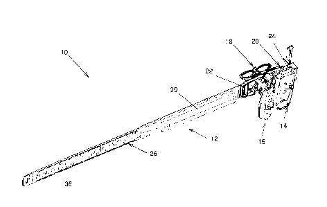
[0021] Referring to Fig. 1, there is shown a hemostatic device 10 in
accordance
with an embodiment of the present invention. The hemostatic device 10 is
usable
for substantially hemostatically sealing a percutaneous puncture in a blood
vessel
of a patient (all not shown in the drawings).
[0022] The hemostatic device 10 includes a bracelet 12 configurable between an
open configuration and a closed configuration, the latter not being shown in
the
drawing. In the closed configuration, the bracelet 12 forms a loop and in the
open
configuration, the bracelet 12 is linear. A compression element 14 is mounted
to
the bracelet 12 and define a compression surface 16 for compressing against
the
patient. The compression element 14 is movable relative to the bracelet 12 so
that
a distance between the bracelet 12 and the compression surface 16 is varied
CA 2994315 2018-02-08
5
when the bracelet 12 and the compression element 14 are moved relative to each
other. The compression element 14 including a lock 18 for selectively locking
the
compression element 14 and bracelet 12 relative to each other.
[0023] In some embodiments, as shown in FIG. 1, the hemostatic device 10
includes two compression elements 14 and 15. These embodiments are usable for
example around the wrists of patients to exert pressure on both the radial and
ulnar arteries. However, any suitable number of compression elements 14 and 15
is usable in the present invention, for example only one compression element
or
more than two compression elements. Furthermore, only some or all of the
compression elements 14 and 15 may be provided with the lock 18. In the
embodiment shown in the drawings, only the compression element 14 is provided
with the lock 18 as compression of the ulnar artery, which is typically not
punctured but compressed only to assist in hemostatis of the punctured radial
artery, is not as critical as compression of the radial artery.
[0024] More specifically, the bracelet 12 includes a substantially rigid base
20
defining substantially opposed bases first and second ends 22 and 24. A
flexible
strap 26 extends from the base first end 22 and a closure 28 is provided as
the
base second end 24. The compression elements 14 and 15 are mounted to the
base 20 as further described hereinbelow. The closure 28 and strap 26 are
configured and sized so that when the bracelet 12 is in the closed
configuration,
the strap 26 engages the closure 28 to maintain the closed configuration.
[0025] The strap 26 may be provided with a deformable portion 30 that is
compressible to provide a cushion when tightened around the wrist of a
patient.
However, in other embodiments, the deformable portion 30 is omitted and either
CA 2994315 2018-02-08
6
replaced by a gel, foam or other deformable material secured to the strap 26,
or
completely omitted without any replacement structure.
[0026] A specific example of the closure 28 and the corresponding structures
on
the strap 26 are now described briefly. These structures are described in
greater
detail in PCT application PCT/CA2011/000903 filed on August 9, 2011, the
contents of which is hereby incorporated by reference in its entirety. It
should be
noted that other mechanisms that allow enclosing safely a limb of a patient
are
also usable in alternative embodiments of the invention.
[0027] Referring for example to FIG. 5, the closure 28 defines a collar 32
through
which the strap 26 is insertable. The closure 28 also includes a flexible
tongue 34.
The strap 26 is provided with ribs 36 (seen in FIG. 1) opposed to the base 20.
The
ribs 36 face the tongue 34 when the bracelet 12 is in the closed configuration
are
configured to engage the tongue 34 so that tightening of the strap 26 is
easily
achieved while loosening of the strap 26 requires manual deflection of the
tongue
34 to disengage the strap 26, and more specifically the ribs 36. To that
effect, the
tongue 34 is also ribbed and the ribs of the tongue 34 and strap 26 are
configured
to easily slide over each other through slanted surfaces when the bracelet 12
is
tightened, while interfering with each other, for example with surfaces that
are
perpendicular to each other, when an attempt to loosen the bracelet 12 is
made.
This type of mechanism is similar to the well known zip ties and similar
devices. In
some embodiments, the closure 28 is provided with a block 38 insertable in the
collar 32 to prevent movements of the tongue 34, so that accidental loosening
of
the strap 26 is unlikely. More details regarding the closure 28 and the
corresponding structures on the strap 26 are provided in the above-referenced
PCT patent application.
CA 2994315 2018-02-08
7
[0028] The compression elements 14 and 15 are mounted to the base 20 so as to
be circumferentially spaced apart from each other when the bracelet 12 in the
closed configuration, with their compression surfaces 16 facing radially
inwardly,
towards the centre of the loop formed by the bracelet 12. The compression
elements 14 and 15 are substantially similar, except for the omission of the
lock 18
in the compression element 15. Only the compression element 14 and the
corresponding structures on the base 20 are therefore described in details
herein,
with the assumption that similar structures and provided for the compression
element 15.
[0029] Referring to FIGS. 2 to 5, the compression element 14 includes and
actuator 42 and a compression pad 44, the latter defining the compression
surface
16. The compression element 15 may includes a compression pad 45 that is
similar in shape to the compression pad 44, or may include a compression pad
45
that differs in shape from the compression pad 44 to accommodate the
functionality of the compression pad 45. The compression pad 44 is mounted to
the base 20 so as to be movable relative thereto in a direction generally
radial
when referring to the closed shape of the bracelet 12. This direction is
typically
perpendicular to a line joining the base first and second ends 22 and 24. The
actuator 42 is operatively coupled to the compression pad 44 for selectively
moving the latter relative to the base 20.
[0030] For example, the base 20 defines a pair of parallel pad mounting
apertures
46 (seen for example in FIG. 8) extending therethrough and an actuator
mounting
aperture 48 extending parallel to the pad mounting apertures 46. In some
embodiments, the pad and actuator mounting apertures 46 and 48 are provided on
a line and extend generally perpendicular to the compression surface 16. The
actuator mounting aperture 48 is threaded.
CA 2994315 2018-02-08
8
[0031] The compression pad 44 includes a pad body 50, defining the
compression surface 16, and a pair of pad stems 52 extending therefrom opposed
to the compression surface 16. The pad stems 52 are each configured and sized
for being substantially snugly received in one of the pad mounting apertures
46
while being longitudinally movable therealong.
[0032] The compression surface 16 may have any suitable shape to provide an
optimal pressure on the puncture without completely occluding the punctured
artery. For example, as better seen for example in FIG. 3, the compression
surface 16 is substantially flat and provided with a bump 55 protruding from
the
remainder thereof.
[0033] The pad body 50 defines a generally cylindrical recess 54 generally
parallel to the pad stems 52. An opening 56 leads in the recess 54. The
opening
56 may be formed by an inward flange 58 so that the opening 56 is smaller in
diameter than the remainder of the recess 54.
[0034] The actuator 42 includes an actuator stem 60 defining a thread 62 that
matches the thread of the actuator mounting aperture 48 so that rotating the
actuator stem 60 moves the actuator stem 60 along the actuator mounting
aperture 48. The actuator stem 60 is terminated by a head 63 engaging the
recess
54 and maintained therein by the flange 58 as the head 62 is larger in
diameter
near its free end that further away from its free end. The head 62 is
rotatable
relative to the recess 54 so that the actuator stem 60 may be rotated without
rotating the compression pad 44. The actuator stem 60 is also provided with a
wing 64 opposed to the head 62 to facilitate rotation of the actuator stem 60
by the
fingers of an intended user. However, other structures such as a ribbed
button,
CA 2994315 2018-02-08
9
among others, are usable instead of the wing 64.
[0035] The lock 18 takes the form of an elongated pin 66 mounted to the
actuator
42, for example to the wing 64. The pin 66 is movable relative to the wing 64
generally parallel to the actuator stem 60 between a lowered (as seen in FIGS.
3
and 4) and a raised (as seen in FIG. 7) position. The pin 66 is mounted for
example in a pair of longitudinally spaced apart pin collars 68 formed in the
wing
64 and includes a pin stem 70 provided at one end thereof with a pin head 72
and
at the other end thereof with a pin protrusion 74 extending laterally
therefrom. The
pin head 72 and pin protrusion 74 limit movements of the pin stem 70 in the
pin
collars 68 between the raised and lowered positions.
[0036] Lock apertures 76 are formed in the base 20 facing the pin 66. The lock
apertures 76 are provided in a generally circular or arc segment shaped
configuration centred on the actuator mounting aperture 48. The lock apertures
76
are configured and sized to substantially snugly receive the pin 66. By
lowering the
pin 66 in a lock aperture 76, rotation of the actuator stem 60 is prevented,
which
achieves a locked configuration. When the pin 66 is raised to disengage the
lock
aperture 76, an unlocked configuration in which the actuator stem 60 may be
rotated relative to the base 20 is achieved. A number of lock apertures 76 if
provided to lock the pin 66 are selected angular positions, corresponding to
selected positions of the compression surface 16. Indicia may be provided
adjacent each lock aperture to identify each lock aperture 76.
[0037] In operation, the compression surfaces 16 are moved adjacent a puncture
to compress and the strap 26 is closed. Then the actuators 42 can be used to
adjust a distance between the compression surface 16 and the base 20, which
CA 2994315 2018-02-08
10
adjusts the pressure exerted on the patient. Once a suitable pressure is
exerted,
the pin 66 may be lowered in a lock aperture 76 to prevent accidental
movements
of the compression pad 44 relative to the base 20. Some protocols require that
the
pressure be gradually released on the puncture. In such cases, once time has
come to release the pressure, the pin 66 may be raised, the actuator 42 may be
turned to release a bit of pressure, and the pin 66 may be lowered in another
lock
aperture 76. This process can be repeated until hemostasis has been reached,
at
which point the bracelet 12 is removed by releasing the strap 26 from the
closure
28.
[0038] Although the present invention has been described hereinabove by way of
preferred embodiments thereof, it can be modified, without departing from the
spirit and nature of the subject invention as defined in the appended claims.
CA 2994315 2018-02-08