Note : Les descriptions sont présentées dans la langue officielle dans laquelle elles ont été soumises.
CA 02994646 2018-02-02
WO 2017/032764
PCT/EP2016/069869
1
CLAMP DEVICE
FIELD OF THE INVENTION
The present invention relates generally to methods and devices for securing
elongate items, such as wires, cables, hoses, tubing, conduits etc. More
particularly,
the invention relates to a clamp device for clamping and locking at least two
elongated components in a spaced interlocked position to each other.
BACKGROUND
Although devices effective in securing elongate items to each other have been
presented within prior art, current devices do not allow elongated items in
any other
interlocked configuration other than in a parallel configuration.
By way of example, a hydraulics cabinet in a fuel dispenser for dispensing
fuel to a vehicle often contains several pipes running in various directions
and
positioned at various distances relative to one another. It can be difficult
to maintain
each pipe in a desired position within the cabinet, and adjacent pipes often
contact
1 5 one another. During use, the pipes can vibrate and wear can occur
between the pipes.
This could potentially cause damage to the pipes and result in leakage of
fuel. Current
solutions include clamps for connecting two parallel types together. However,
these
clamps cannot be used with pipes that do not run parallel to one another.
Moreover,
such clamps are only configured to maintain pipes at a specific distance.
Accordingly, there remains a need for improved methods and devices for
clamping two structures.
SUMMARY
An object of the invention is to provide a clamp device enabling freely
selected angulated interlocked position for the elongated items while still
providing a
fixed distance in between the elongated items to avoid vibration, chaffing,
heat
transfer or other adverse consequences of insufficient spacing between the
elongated
items.
CA 02994646 2018-02-02
WO 2017/032764
PCT/EP2016/069869
2
Another object of the invention is to provide a clamp device enabling two
different distances between the elongated items using one and the same
clamping
device.
According to a first aspect of the invention, these and other objects are
achieved, in full or at least in part, by a clamp device comprising a first
section
having a first base and at least one receiver configured to receive and clamp
at least a
first elongate component; and a second section having a second base and at
least one
receiver configured to receive and clamp at least a second elongated
component.
According to this first aspect, said first and said second bases have coupling
structures to be rotatably assembled to one another holding said first and
said second
elongated component in an interlocked position.
According to one embodiment, said first and second bases have coupling
structures configured to rotatably assemble to one another to allow rotation
of first
and second elongated components within parallel planes of motion.
According to one embodiment, said first base and said first receiver is
integrally formed, such as a one-unit piece.
According to one embodiment, said second base and said second receiver is
integrally formed, such as one-unit piece.
According to one embodiment, at least one of said first and second section is
configured to provide at least two different distances between said first and
said
second elongate components in said interlocked position.
According to another embodiment, said receivers have a C-shaped
configuration to receive and clamp said at least first and second elongated
components.
According to a further embodiment, said first base has a sleeve member
arranged axially perpendicular from said first receiver and off center from
said first
receiver, thereby providing two different distances between said first
receiver and
CA 02994646 2018-02-02
WO 2017/032764
PCT/EP2016/069869
3
said second receiver when said first base is assembled to said second base in
the two
different assembling possibilities for said first and said second section.
According to one embodiment, said first base has a sleeve member arranged
axially perpendicular and tangential from said first receiver, preferably off
center
from said first receiver.
According to one embodiment, said second base has a shaft member arranged
axially perpendicular from said second receiver.
According to another embodiment, said second base has a shaft member
arranged axially perpendicular and tangential from said second receiver and
off center
1 0 from said second receiver.
According to an additional embodiment, said first and said second base has a
locking arrangement for locking said first and second section together after
assembling.
According to a further embodiment, said locking arrangement comprises a
friction based locking arrangement. In one embodiment said locking arrangement
comprises a conical shaped shaft member on said second base for inserting in a
sleeve
member on said first base.
According to one embodiment, said locking arrangement comprises a
protrusion arranged on a shaft member on said second base and a corresponding
recess in a sleeve member on said first base for receiving said protrusion
when
assembling and coupling said first and said second section.
According to one embodiment, said locking arrangement comprises at least
one riffled or fluted surface for friction engagement between surfaces of said
coupling
structures of said first and second bases.
According to a second aspect, these and other objects are also achieved, in
full
or at least in part, by a fuel dispenser comprising: a hydraulics compartment
having
fuel dispensing components extending therethrough, the hydraulics compartment
CA 02994646 2018-02-02
WO 2017/032764
PCT/EP2016/069869
4
having at least two tubes extending therethrough, and the hydraulics
compartment
having a clamping device according any of the above disclosed embodiments,
wherein a first portion of the clamping device is coupled to the first tube
and a second
portion of the clamping device is coupled to the second tube.In another
embodiment,
a clamping device is provided and includes first and second portions, with
each
portion being configured to engage a tubular structure such that the first and
second
portions can maintain the tubular structures in a fixed position relative to
one another.
The clamping device can be selectively matable in a plurality of
configurations such
that the first and second portions can maintain the first and second tubular
structures
in a parallel orientation relative to one another, a non-parallel orientation
relative to
one another, and at at least two different distances relative to one another.
The first and second portions can mate to one another using a variety of
techniques. For example, the first and second portions can be rotatably
matable
relative to one another to allow the first and second portions to selectively
maintain
first and second elongate structures in one of the parallel and non-parallel
orientations. In other aspects, the second portion can be insertable into the
first
portion in a first direction to maintain first and second elongate structures
at a first
distance apart, and the second portion can be insertable into the first
portion in a
second direction to maintain first and second elongate structures at a second
distance
apart that differs from the first distance. In another embodiment, the second
portion
can be insertable into a first bore in the first portion to maintain first and
second
elongate structures at a first distance apart, and the second portion can be
insertable
into a second bore in the first portion to maintain first and second elongate
structures
at a second distance apart that differs from the first distance.
The clamping device can also include other features. For example, at least
one of the first and second portions can include a locking element for locking
the first
and second portions together.
In yet another embodiment, a clamping device is provided and includes a first
member having a receiver portion configured to receive and clamp a first tube,
and
having a first mating portion. The clamping device also include a second
member
CA 02994646 2018-02-02
WO 2017/032764
PCT/EP2016/069869
having a receiver portion configured to receive and clamp a second tube, and
having a
second mating portion that is configured to mate with the first mating portion
to hold
first and second tubes in a fixed position relative to one another. The second
mating
portion can be insertable into the first mating portion in a first direction
in which first
5 and tubes are held at a first distance, and the second mating portion can
be insertable
into the first mating portion in a second direction in which first and second
tubes are
held at a second distance that is greater than the first distance.
In one embodiment, the first and second mating portions can be rotatably
matable such that a radial position of the receiver portion of each of the
first and
second members about a longitudinal axis of the first mating portion is
adjustable.
By way of non-limiting example, the second mating portion can be a male member
and the first mating portion can be a female member. The second mating portion
can
be in the form of an elongate shaft and the first mating portion can include a
lumen
configured to receive the elongate shaft. In one embodiment, an inner diameter
of the
lumen is expandable and compressible. In other embodiments, the elongate shaft
can
include a protrusion formed on a terminal end thereof and configured to engage
the
first mating portion so as to lock the second mating portion to the first
mating portion.
In other aspects, the second mating portion can be held by a friction fit
within the first
mating portion.
In another embodiment, the first receiver portion can have a central
longitudinal axis along which a first tube is configured to extend when mated
thereto,
and the first mating portion can have a lumen extending therethrough along an
axis
that is substantially perpendicular to the central longitudinal axis. The
second
receiver portion can have a central longitudinal axis along which a second
tube is
configured to extend when mated thereto, and the second mating portion can
extend
along an axis that is substantially perpendicular to a central longitudinal
axis.
In another embodiment, a fuel dispenser is provided and includes a hydraulics
compartment having fuel dispensing components extending therethrough. The
hydraulics compartment can have at least two tubes extending therethrough, and
the
hydraulics compartment can have a clamping device disposed therein. A first
portion
CA 02994646 2018-02-02
WO 2017/032764
PCT/EP2016/069869
6
of the clamping device can be coupled to the first tube and a second portion
of the
clamping device can be coupled to the second tube. The first and second
portions of
the clamping device can be selectively matable to one another in a plurality
of
configurations to maintain the first and second tubes at a plurality of
angular
orientations relative to one another and at a plurality of distances from one
another
In one embodiment, the clamping device can have a first configuration in
which the first and second portions maintain the first and second tubes at a
first
distance, and the clamping device can have a second configuration in which the
first
and second portions maintain the first and second tubes at a second distance
that is
1 0 greater than the first distance.
In another embodiment, the clamping device can have a first configuration in
which the first and second portions maintain the first and second tubes in a
parallel
configuration, and the clamping device have a second configuration in which
the first
and second portions maintain the first and second tubes in a non-parallel
configuration.
The fuel dispenser can also include a second clamping device coupled to a
third tube and a fourth tube disposed within the hydraulics compartment for
selectively maintaining the third and fourth tubes at one of a plurality of
angular
orientations relative to one another, and for selectively maintaining the
third and
fourth tubes at one of a plurality of distances from one another.
Other objectives, features and advantages of the present invention will appear
from the following detailed disclosure, from the attached claims, as well as
from the
drawings. It is noted that the invention relates to all possible combinations
of features.
Generally, all terms used in the claims are to be interpreted according to
their
ordinary meaning in the technical field, unless explicitly defined otherwise
herein. All
references to "a/an/the [element, device, component, means, step, etc.]" are
to be
interpreted openly as referring to at least one instance of said element,
device,
component, means, step, etc., unless explicitly stated otherwise.
CA 02994646 2018-02-02
WO 2017/032764
PCT/EP2016/069869
7
As used herein, the term "comprising" and variations of that term are not
intended to exclude other additives, components, integers or steps.
BRIEF DESCRIPTION OF THE DRAWINGS
The invention will be described in more detail with reference to the appended
schematic drawings, which show an example of a presently preferred embodiment
of
the invention.
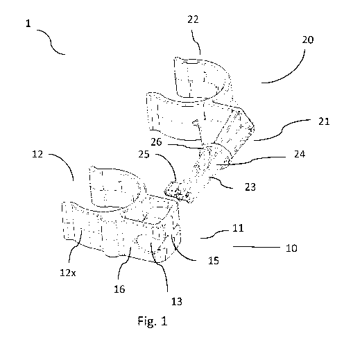
Fig. 1 is a perspective view of a clamp device according to one embodiment
with the first and second section separated.
Fig. 2a is a perspective view of the clamp device assembled in the direction
as
positioned in Fig. 1.
Fig. 2b is a front view of the clamp device as assembled in Fig. 2a with
clamped pipes.
Fig. 2c is a backside view of the clamp device with clamped pipes as shown in
Fig. 2b.
Fig. 3a is a perspective view of the clamp device as assembled in Fig. 2a, but
with one section rotated about 90 from the position in Fig. 2a.
Fig. 3b is a perspective view of the clamp device of like the one in Fig. 2a
with clamped pipes, but with one section rotated about 90 .
Fig. 4 is a perspective view of the clamp device of Fig. 2a, but with one
section rotated about 180 .
Fig. 5 is a perspective view of a clamp device of Fig. 1, but with one section
turned to be assembled from the other side of said section with the other
section.
Fig. 6a is perspective view of the clamp device assembled in the direction as
positioned in Fig. 5.
CA 02994646 2018-02-02
WO 2017/032764
PCT/EP2016/069869
8
Fig. 6b is a front view of the clamp device as assembled in Fig. 6a with
clamped pipes.
Fig. 7a is a perspective view of the clamp device as assembled in Fig. 6a, but
with one section rotated about 120 from the position in Fig. 6a.
Fig. 7b is a perspective view of the clamp device of Fig. 7a with clamped
pipes.
Fig. 8 is a cross-sectional view of a clamp device according to another
embodiment.
Fig. 9 is a perspective view of a fuel dispenser.
It is noted that the drawings are not necessarily to scale. The drawings are
intended to depict only typical aspects of the subject matter disclosed
herein, and
therefore should not be considered as limiting the scope of the disclosure. In
the
drawings, like numbering represent like elements between the drawings.
DETAILED DESCRIPTION
The present invention will now be described more fully hereinafter with
reference to the accompanying drawings, in which currently a preferred
embodiment
of the invention is shown. The present invention may, however, be embodied in
many
different forms and should not be construed as limited to the embodiments set
forth
herein; rather, these embodiments are provided for thoroughness and
completeness,
and to fully convey the scope of the invention to the skilled addressee. Like
reference
characters refer to like elements throughout.
Various methods and devices are provided for maintaining two structures in a
desired spatial relationship relative to one another. In particular, a
clamping device is
provided having first and second clamping members that are matable to one
another
in several configurations so as to allow the clamping device to couple between
two
structures that extend at various angular orientations relative to one
another. For
example, in one configuration the clamping device can couple between two
tubular
CA 02994646 2018-02-02
WO 2017/032764
PCT/EP2016/069869
9
structures that extend in a parallel orientation relative to one another. In
another
configuration, the clamping device can couple between two tubular structures
that
extend in a nonparallel configuration relative to one another. The clamping
device
can also selectively maintain the parallel and non-parallel structures at
various
distances from one another.
While the clamping device has applicability in various applications, in one
exemplary embodiment the clamping device is particularly suitable for use in a
fuel
dispenser. The hydraulics cabinet of a fuel dispenser often contains several
tubes/pipes extending therethrough for the delivery of fuel or other fluids.
These
tubes can contact one another at various locations, and such contact can cause
wear
which can result in potential damage or leakage. The clamping devices
disclosed
herein can be used to maintain two tubular structures at a fixed distance from
one
another so as to prevent contact between the structures. The modularity of the
clamping device allows a single clamping device to connect in various
orientations so
as to accommodate elongate structures extending at various angles relative to
one
another and at various distances from one another.
Figs. 1-7 show a clamp device 1 according to one embodiment. The illustrated
clamp device 1 has a first section 10 and a second section 20. The first and
second
sections 10, 20 are matable to one another in various configurations so as to
maintain
first and second structures at a desired orientation relative to one another.
The first section 10, e.g. a first clamping member, has a first receiver 12
which is configured to receive and clamp a first pipe 30, and a first base 11
for
meeting with the second section 20. In the embodiment shown in the figures the
first
receiver 12 has a C-shaped configuration for receiving and clamping a first
pipe 30.
The C-shaped configuration defines a central longitudinal axis extending
therethrough along which a first pipe will extend. While the illustrated
receiver has a
C-shaped configuration, other forms are also possible as long as it may
receive and
clamp an elongated component 30, 40, such as a pipe. In one embodiment the
receiver is manufactured in a material that will provide a resilient snap fit
with the
elongated component. The first section may in one embodiment optionally have
more
CA 02994646 2018-02-02
WO 2017/032764
PCT/EP2016/069869
than one receiver, such as two, three or more receivers arranged in parallel
positions
to one another (not shown), all being connected and arranged with the first
base 11.
As indicated above, the first base 11 can be in the form of a mating element
for mating with the second section 20. The illustrated first base 11 is in the
form of a
5 female housing having a bore or sleeve member 13 extending therethrough.
The first
base 11 is formed on the back side of the C-shaped receiver 12, such that a
pipe
seated in the receiver will be positioned on one side of the first section and
the sleeve
member 13 is positioned on an opposite side of the first section. As further
shown in
Fig. 1, the sleeve member 13 is arranged such that its longitudinal axis
extends
10 substantially perpendicular to the longitudinal axis of C-shaped first
receiver 12.
Moreover, the illustrated sleeve member 13 is offset relative to the first
receiver 12.
In particular, as shown in Fig. 1 an outer wall 16 is substantially aligned
along a plane
with an outer wall 12x of the first receiver 12, whereas the opposite outer
wall of the
base 11 is offset and out-of-plane relative to the outer wall of the first
receiver 12 that
is opposite to outer wall 12x.
The second section 20 has a second base 21 and a second receiver 22, which
second receiver 22 is configured to receive and clamp a second pipe 40. In the
embodiment shown in the figures the second receiver 22 has a C-shaped
configuration similar to that of the first receiver 11. However, as stated
above, other
forms are possible and different forms for the first and second receiver are
also
possible, as long as each receiver may receive and clamp an elongated
component 30,
40, such as a pipe. Again, the receiver is, in one embodiment, manufactured in
a
material allowing resilient snap fit with the elongated component. The second
section
20 may also, similar to the first section 10, have more than one receiver,
such as two,
three or more receivers arranged in parallel positions to one another (not
shown), all
being connected and arranged with the second base 21.
The illustrated second base 21 is in the form of a male mating member that is
configured to slidably mate with the sleeve 13 in the first base 11. As shown,
the
second base 21 includes a shaft member 23 having a longitudinal axis that
extends
perpendicular to a central longitudinal axis of a pipe seated in the second
receiver.
CA 02994646 2018-02-02
WO 2017/032764
PCT/EP2016/069869
11
The sleeve member 13 is arranged to receive the shaft member 23 such that
the first and second sections 10, 20 can rotate relative to one another. Such
a
configuration allows the first and second receivers 12, 22 to be radially
aligned with
one another, or to be radially offset from one another. In an exemplary
embodiment,
the first and second sections 10, 20 can freely rotate 360 degrees relative to
one
another, and rotation can occur without causing any contact between the tubes
seated
in the receivers 12, 22. For example, the tubes 30, 40 seated in the receivers
12, 22
can rotate within parallel planes relative to one another.
In the illustrated embodiment, as indicated above the sleeve member 13 on the
first portion is arranged off center from the first receiver 12. With such an
arrangement the first section 10 provides for two different distances, dmin,
dmax,
between the first and second receivers 12, 22, depending on in which direction
the
first section 10 is joined and assembled with the second section 20. For
example,
when the first section 10 is inserted into a first open end of the sleeve 13,
as
positioned and assembled in Fig. 1 - 4, a shorter fixed interlocked position,
dmin, is
provided between the two elongated components 30, 40. Conversely, when the
first
section 10 is inserted into a second, opposite open end of the sleeve 13, as
positioned
and assembled in Fig. 5 - 7, a longer fixed interlocked position, dmax, is
provide
between the two elongated components 30, 40.
In the illustrated embodiment, the shaft member 23 is also arranged off center
from the second receiver 22, which adds to the specific distance dmin, dmax
between
the first and second elongated members 30, 40. In particular, a first end of
the shaft
member 23 is connected to the second receiver 22 at a location that is offset
from a
mid-point of the second receiver 22.
Further, the shaft member 23 may have a stop seat 26 arranged to engage a
front edge surface 17 of the sleeve member 13 when the shaft member 23 has
been
inserted fully or to a predetermined extent into the sleeve member 13. The
stop seat
26 is in the form of a flange and it is positioned at a location that is a
distance apart
from an outer sidewall of the second receiver 22 to facilitate the offset
mating
arrangement between the first and second portions of the clamping device.
Other
CA 02994646 2018-02-02
WO 2017/032764
PCT/EP2016/069869
12
alternatives, limiting to what extent the shaft member 23 may be inserted into
the
sleeve member 13, are also possible.
The illustrated embodiment further has a locking arrangement for locking the
first section 10 and the second section 20 at a desired orientation relative
to one
another after assembling. Such a locking arrangement may be provided by a
friction
fit between the sleeve member 13 and the shaft member 23. Having a friction
fit
provides a continuous system which may compensate for any deviations or pipe
movements. One example of such a friction fit may be provided by a conical
shaped
shaft member 23 with a widening part towards end 24 arranged closest to the
second
receiver 22. Another example is a riffled or a fluted surface of the shaft
member 23
and/or on an inner sleeve surface, which will lock the two sections together
by a
friction fit between the surface of the shaft member and the inner sleeve
surface.
Another example of locking arrangement is a shaft member 23 having at least
two
different diameters and a sleeve member 13 having a corresponding key-hole fit
to
the shaft member 23. In yet another embodiment the shaft member 23 has a
splined
surface, and the inner wall of the sleeve member 13 has a corresponding
splined
surface for engaging fit.
The illustrated embodiment further has a keyed feature, shown in the form of
a protrusion 25, arranged on the shaft member 23 opposite the second receiver
22. A
corresponding slot or recess 15 is formed in the sleeve member 13 on the first
base 11
enabling insertion of the shaft member 23 with the protrusion 25 into the
sleeve
member 13, wherein the protrusion 25 passes in the recess 15 during insertion.
The
recess 15 extends along the length of the sleeve member 13 such that an inner
diameter of the sleeve member 13 is resilient. When the shaft member 23 has
been
fully inserted into the sleeve member 13 and the protrusion 25 has passed
through the
recess 15 and out on an opposite side of the sleeve member 13, the first and
second
sections 10, 20 are rotatable connected, and the shaft member 23 may be
rotated
within the sleeve member 13.
By rotating the first and/or the second section, the protrusion 25 is turned
away from the recess 15 to engage with an outer wall 16 on the opposite side
of the
CA 02994646 2018-02-02
WO 2017/032764
PCT/EP2016/069869
13
sleeve member 13, which will lock the first section 10 to the second section
20.
Depending on the rotation degree, the clamp device will provide a clamping and
locking of two elongated items in a parallel or an angulated interlocked
position, such
as is shown in Figs. 2a, 2b, 2c, 3a, 3b, 6a, 6b, 7a and 7b. In order to
facilitate locking,
the outer wall 16 can be chamfered on opposite sides of the recess 15 so as to
allow
the protrusion 25 to ride up along a slope on the sidewall 16 during rotation
away
from the recess 15, thereby pulling the two sections 10, 20 into closer
engagement
with one another.
In one embodiment, one or more recesses are arranged on the outer wall 16
for snap fit with an adjacent surface of the protrusion 25 (not shown). The
recesses
correspond to predetermined angulated interlocking position between the first
and the
second sections 10, 20.
In another embodiment, one or more recesses are arranged on the front surface
17 of the first section 10, and a protrusion to engage therewith are arranged
on the
seat surface 26 on the second section 20 (not shown).
However, the first section 10 and the second section 20 may also be locked to
each other without rotation of the first and/or the second section 10, 20. In
one
embodiment the protrusion 25 has a press fit with the recess 15 of the sleeve
member
13 in such a way that the recess 15 provides a resilient fit around the
protrusion 25
during insertion, and when the shaft member 23 has been fully inserted into
the sleeve
member 13 and the protrusion 25 has passed through the recess 15 and out on an
opposite side of the sleeve member 13, the recess 15 may spring back and the
protrusion 25 will engage with the outer wall edges 16 around the recess
opening on
the opposite side of the sleeve member 13. Such a coupling of the first and
second
section 10, 20 is shown in Fig. 4. The different disclosed locking arrangement
may be
combined with each other in different combinations.
Fig. 8 illustrates another embodiment of a clamping device 101 that is
configured to maintain two structures, such as two tubes/pipes, in a plurality
of
configurations. Clamping device 101 is similar to clamping device 1 shown in
Figs.
1-7 and is configured to selectively maintain two structures in a plurality of
angular
CA 02994646 2018-02-02
WO 2017/032764
PCT/EP2016/069869
14
orientations relative to one another, as well as at a plurality of distances
from one
another. As shown in Fig. 8, the clamping device 101 includes a first section
110,
e.g. a first clamping member, having a first receiver 112 which is configured
to
receive and clamp a first pipe, and having a first base 111 for mating with a
second
section 120. The second section 120 has a second receiver 122 which is
configured to
receive and clamp a second pipe, and a second base 121 that mates with the
first base
111. The first and second receivers 112, 122 are similar to the receivers 12,
22
described above and can thus have all of the same features described above.
In this embodiment, the first and second bases 111, 121 differ from the above
embodiment. In particular, in this embodiment the second base 121 has an
elongate
configuration with at least one bore extending therethrough and forming a
female
mating component. As shown in Fig. 8, the second base 121 has two bores 113,
115
formed thereon. A person skilled in the art will appreciate that the second
base 121
can have a single bore, or a plurality of bores, e.g., three bores, four
bores, etc. Each
bore can have a shape that is complementary to a shape of a male member on the
first
base 111, such as cylindrical, hexagonal, square, etc. The bores can be spaced
along
a longitudinal axis of the second base 121, and the distance between the bores
can be
configured to provide a desired preselected distance between the first and
second
receivers 112, 122. Each bore can also include a locking feature, e.g., such
as a taper
for frictionally engaging a male member on the first base 111, or any other
locking
feature as described herein or known in the art.
As indicated above, the first base 111 can be in the form of a male member,
e.g., a shaft, that is configured to be inserted into the bore in the second
base 121.
The first base 111 can have a length that allows the first base 111 to pass at
least
partially into one of the bores in the second base 121, and more preferably
that allows
the first base 111 to pass entirely through one of the bores in the second
base 121, as
shown in Fig. 8.
When passed fully through the bore, a locking feature can help retain the
first
and second bases 111, 121 in mating engagement with one another. The locking
feature can have various configurations, as previously disclosed herein. For
example,
CA 02994646 2018-02-02
WO 2017/032764 PCT/EP2016/069869
the bore 113, 115 in the second base 121 can include a slot extending
therethrough for
receiving a protrusion formed on the first base 111. Once passed through the
slot, the
first base 111 can be rotated, thereby rotating the protrusion so as to allow
the
protrusion to engage an outer wall of the second base 121 to lock the
components
5 together.
In another embodiment, the locking feature can provide a snap-fit between the
first and second bases 111, 121. For example, the first base 111 can be in the
form of
a split shaft having radially extending flanges formed on a terminal end
thereof. The
split configuration of the shaft will allow the flanges to be compressed
toward one
10 during insertion through the bore in the second base 121, and to expand
once fully
passed through the bore to thereby engage the outer sidewall of the second
base 121
so as to prevent removal of the first base 111 from the second base 121. The
first
base 111 can remain freely rotatable, or a friction fit can help prevent free
rotation.
Other locking features include, for example, threads formed on the first base
15 111 for mating with a threaded nut or other threaded locking element.
In other embodiments, the first base 111 can be in the form of a spline shaft,
having ridges or teeth that mesh with corresponding grooves formed in the bore
in the
second base 121. The number of ridges or teeth and grooves can correspond to a
desired number of rotational positions that the first section 110 can mate to
the second
section 120. When mated, the first base 111 will be prevented from rotating
relative
to the second base 121.
In use, clamping device 101 provides rotational adjustment between the first
base 111 and the second base 121, thereby allowing the first receiver 112 to
be
position at any angle as may be desired relative to the second receiver 121.
Such a
configuration allows a single clamping device to be used to clamp two
structures
extending at any angle relative to one another. The clamping device 101 also
allows
for use with two structures positioned at various distances from one another.
The first
base 111 can be selectively inserted into a desired hole 113, 115 in the
second base
121 so as to define a distance between the receivers 112, 122. In the
illustrated
embodiment, when mated to the first hole 113 the receivers will be positioned
at a
CA 02994646 2018-02-02
WO 2017/032764
PCT/EP2016/069869
16
minimum distance, whereas the first base 111 is mated to the second hole 115
the
receivers will be positioned at a greater maximum distance. Again, a person
skilled
in the art will appreciate that the second base 121 can include any number of
holes at
any position to allow the receivers 112, 122 to be maintained at a plurality
of
distances from one another.A skilled person will appreciate that a number of
modifications of the embodiments described herein are possible without
departing
from the scope of the invention, which is defined in the appended claims.
In use, in one embodiment one or more clamping devices can be coupled to
tubes extending within a hydraulics compartment on a fuel dispenser so as to
maintain the tubes at a fixed distance relative to one another. Fig. 9
illustrates one
embodiment of a fuel dispenser 300 that can include at least one clamping
device
located in the hydraulics compartment. As shown, the illustrated fuel
dispenser 300
generally includes an electronics module 310 that contains payment processing
components, and a hydraulics module 320 that forms the base of the dispenser
and
that contains fuel dispensing components, such as pumps and meters, as well as
various tubes/hoses for delivering the fuel. As further shown, the illustrated
fuel
dispenser 300 also includes a hose 330 having a nozzle 332 on a terminal end
thereof
for delivering fuel from the hydraulics compartment therethrough to a vehicle.
A
person skilled in the art will appreciate that the fuel dispenser can have
virtually any
configuration and should not be limited to the configuration shown in Fig. 9.
In one embodiment, one or more clamping devices as disclosed herein can be
used, for example, in the hydraulics compartment 320 to maintain two
tubes/hoses/pipes at a fixed position relative to one another. The modularity
of the
clamping device allows a single clamping device to connect to two tubes that
extend
parallel to one another or that extend non-parallel at various angular
orientations
relative to one another. The adjustability of the clamping device also allows
the same
clamping device to connect to tubes that are spaced apart at varying distances
from
one another.
For example, the first section 10 and second section 20 of a clamping device
can be mated as shown in Fig. 2a such that the receivers are aligned and the
distance
CA 02994646 2018-02-02
WO 2017/032764
PCT/EP2016/069869
17
between the receivers is at a minimum distance. In such a configuration, the
clamping
device will maintain the two parallel tubes at a fixed minimum distance
relative to
one another, as shown in Fig. 2b.
A second clamping device can be provided and the first and second sections
10, 20 can be mated to one another in a second configuration in which the
receivers
are likewise aligned, however the distance between the receivers is at a
maximum
distance. The second clamping device can maintain two parallel tubes at a
fixed
maximum distance relative to one another as shown in Fig. 2c.
Additional clamping devices can also be coupled to tubes that extend in a
nonparallel orientation relative to one another. For example, Figs. 3a-3b
illustrate a
configuration of a clamping device for maintaining two non-parallel tubes 30,
40 at a
minimum distance relative to one another, while Figs. 7a-7b illustrate a
configuration
of a clamping device for maintaining two nonparallel tubes 30, 40 at a maximum
distance relative to one another. Any number of clamping devices can be used
in a
fuel dispenser as needed.
A person skilled in the art will appreciate that the clamping devices
disclosed
herein can also be used in a variety of other applications, and are not
limited to use in
a fuel dispenser.
Below some further aspects of the invention are disclosed:
Aspect 1. A clamping device, comprising:
a first portion configured to engage a first elongate structure; and
a second portion configured to engage a second elongate structure;
wherein the first and second portions are selectively matable in a plurality
of
configurations such that the first and second portions can maintain first and
second
elongate structures in at least a parallel orientation relative to one
another, in a non-
parallel orientation relative to one another, and at at least two different
distances
relative to one another.
Aspect 2. The clamping device of aspect 1, wherein the first and second
portions
are rotatably matable relative to one another to allow the first and second
portions to
CA 02994646 2018-02-02
WO 2017/032764 PCT/EP2016/069869
18
selectively maintain first and second elongate structures in one of the
parallel and
non-parallel orientations.
Aspect 3. The clamping device of aspect 1, wherein the second portion is
insertable into the first portion in a first direction to maintain first and
second
elongate structures at a fixed distance apart, and wherein the second portion
is
insertable into the first portion in a second direction to maintain first and
second
elongate structures at a second distance apart that differs from the first
distance.
Aspect 4. The clamping device of aspect 1, wherein the second portion is
insertable into a first bore in the first portion to maintain first and second
elongate
structures at a first distance apart, and wherein the second portion is
insertable into a
second bore in the first portion to maintain first and second elongate
structures at a
second distance apart that differs from the first distance.
Aspect 5. The clamping device of aspect 1, wherein at least one of the
first and
second portions includes a locking element for locking the first and second
portions
together.
Aspect 6. A clamping device, comprising:
a first member having a receiver portion configured to receive and clamp a
first tube, and having a first mating portion;
a second member having a receiver portion configured to receive and clamp a
second tube, and having a second mating portion that is configured to mate
with the
first mating portion to hold first and second tubes in a fixed position
relative to one
another;
wherein the second mating portion is insertable into the first mating portion
in
a first direction in which first and tubes are held at a first distance, and
the second
mating portion is insertable into the first mating portion in a second
direction in
which first and second tubes are held at a second distance that is greater
than the first
distance.
Aspect 7. The device of aspect 6, wherein the first and second mating
portions
are rotatably matable such that a radial position of the receiver portion of
each of the
CA 02994646 2018-02-02
WO 2017/032764 PCT/EP2016/069869
19
first and second members about a longitudinal axis of the first mating portion
is
adjustable.
Aspect 8. The device of aspect 6, wherein the second mating portion
comprises a
male member and the first mating portion comprises a female member.
Aspect 9. The device of aspect 6, wherein the second mating portion
comprises
an elongate shaft and the first mating portion comprises a lumen configured to
receive
the elongate shaft.
Aspect 10. The device of aspect 9, wherein an inner diameter of the lumen
is
expandable and compressible.
Aspect 11. The device of aspect 9, wherein the elongate shaft includes a
protrusion formed on a terminal end thereof and configured to engage the first
mating
portion so as to lock the first mating portion to the second mating portion.
Aspect 12. The device of aspect 6, wherein the second mating portion is
held by a
friction fit within the first mating portion.
1 5 Aspect 13. The device of aspect 6, wherein the first receiver
portion has a central
longitudinal axis along which a first tube is configured to extend when mated
thereto,
and wherein the first mating portion has a lumen extending therethrough along
an
axis that is substantially perpendicular to the central longitudinal axis.
Aspect 14. The device of aspect 6, wherein the second receiver portion
has a
central longitudinal axis along which a second tube is configured to extend
when
mated thereto, and wherein the second mating portion extends along an axis
that is
substantially perpendicular to a central longitudinal axis.
Aspect 15. A fuel dispenser, comprising:
a hydraulics compartment having fuel dispensing components extending
therethrough, the hydraulics compartment having at least two tubes extending
therethrough, and the hydraulics compartment having a clamping device disposed
therein, wherein a first portion of the clamping device is coupled to the
first tube and
CA 02994646 2018-02-02
WO 2017/032764 PCT/EP2016/069869
a second portion of the clamping device is coupled to the second tube, the
first and
second portions of the clamping device being selectively matable to one
another in a
plurality of configurations to maintain the first and second tubes at a
plurality of
angular orientations relative to one another and at a plurality of distances
from one
5 another.
Aspect 16. The fuel dispenser of aspect 15, wherein the clamping device
has a
first configuration in which the first and second portions maintain the first
and second
tubes at a first distance, and wherein the clamping device has a second
configuration
in which the first and second portions maintain the first and second tubes at
a second
10 distance that is greater than the first distance.
Aspect 17. The fuel dispenser of aspect 15, wherein the clamping device
has a
first configuration in which the first and second portions maintain the first
and second
tubes in a parallel configuration, and wherein the clamping device has a
second
configuration in which the first and second portions maintain the first and
second
15 tubes in a non-parallel configuration.
Aspect 18. The fuel dispenser of aspect 15, further comprising a second
clamping
device coupled to a third tube and a fourth tube disposed within the
hydraulics
compartment for selectively maintaining the third and fourth tubes at one of a
plurality of angular orientations relative to one another, and for selectively
20 maintaining the third and fourth tubes at one of a plurality of
distances from one
another.