Note : Les descriptions sont présentées dans la langue officielle dans laquelle elles ont été soumises.
LAP WELDING METHOD OF STEEL SHEET AND LAP WELD JOINT OF STEEL
SHEET
[Technical Field of the Invention]
[0001]
The present invention relates to a lap welding method of a steel sheet and a
lap
weld joint of a steel sheet.
The present application claims priority on the basis of Japanese Patent
Application No. 2015-182846, filed on September 16, 2015 in Japan.
[Related Art]
[0002]
Recently, in the automotive field, there have been a demand for the weight
reduction of vehicle bodies in order for gas mileage improvement and the
reduction of
CO2 emission and a demand for the strengthening of vehicle body members in
order for
collision safety improvement. In addition, in order to meet such demands, high-
strength
steel sheets are used for vehicle body members, a variety of components, and
the like.
[0003]
In steps for manufacturing vehicle body members made of high-strength steel
sheets and steps for attaching components made of high-strength steel sheets,
mainly,
resistance spot welding (hereinafter, also simply referred to as spot welding)
is broadly
used. For example, as basic structural members constituting vehicle bodies,
lap weld
joints of steel sheets are used, and these lap weld joints are manufactured by
overlapping
two steel sheet members having a hat shape and spot-welding the overlapping
portions.
FIG. 16A is a horizontal cross-sectional view showing a lap weld joint 60 of a
steel sheet
of the related art and is a view for describing a lap welding method of a
steel sheet of the
related art. In addition, FIG. 16B is a partial enlarged view of FIG. 16A.
Meanwhile,
in FIG. 16B, one of a pair of welding electrodes 90 is not shown.
- 1 -
CA 2994926 2019-01-23
CA 02994926 2018-02-06
[0004]
As shown in FIG. 16A, in the lap welding method of the related art, two steel
sheet members 70 which respectively have a pair of flange portions 72 and a
pair of
standing wall portion 74 that stands from these flange portions 72 and have a
hat-like
cross-sectional shape are overlapped with each other, and then the flange
portions 72 of
these steel sheet members 70 are interposed between the pair of welding
electrodes 90
and are spot-welded, thereby forming solidified portions 80 (hereinafter,
referred to as
"nuggets") between the flange portions 72.
[0005]
As shown in FIG. 16A and FIG. 16B, the welding electrode 90 that is used for
the spot welding has a cylindrical main body portion 92 and a taper portion 94
that tapers
toward a tip end. Meanwhile, the diameter 4) of the main body portion 92 is,
for
example, 16 mm, and the diameter 4)' of a tip end surface 94a of the taper
portion is, for
example, 6 mm. In addition, the width w of the flange portion 72 of the steel
sheet
member 70 is, for example, 15 to 20 mm. In addition, the tip end surface 94a
of the
taper portion 94 comes into contact with the flange portion 72 of the steel
sheet member
70, whereby electric currents flow in the flange portion 72, and the nugget 80
is formed.
That is, the diameter 4)' of a tip end surface 94a of the welding electrode 90
determines
an electric conduction diameter and almost coincides with the maximum nugget
diameter
to be obtained.
[0006]
In a case in which two steel sheet members 70 are spot-welded using the
welding electrodes 90, when the standing wall portion 74 of the steel sheet
member 70
and the welding electrode 90 come into contact with each other, the standing
wall portion
74 and the welding electrode 90 are electrically conducted to each other, and
there is a
concern that it may not be possible to weld the flange portions 72 of the
steel sheet
members 70. Therefore, during the spot welding of the steel sheet members 70,
it is
necessary to provide a gap for avoiding interference between the standing wall
portion 74
and the welding electrode 90. Furthermore, as described above, the welding
electrode
90 has the taper portion 94 that tapers toward the tip end. Therefore, the
nugget 80 is
formed at a location a predetermined distance away from the standing wall
portion 74.
- 2 -
CA 02994926 2018-02-06
[0007]
In the lap weld joint 60 obtained by the lap welding method of the related
art,
the nuggets 80 are formed at locations away from the standing wall portion 74
as
described above, and thus, in a case in which a tensile stress acts thereon,
the flange
portions 72 of the two steel sheet members 70 easily deform in a direction in
which the
flange portions move away from each other (that is, torn-open deformation),
consequently, stress focuses on an end portion of the nugget 80, and the joint
strength
decreases. In addition, even in a case in which a torsional moment acts on the
surrounding of a central axis line CL of the lap weld joint 60, torn-open
deformation is
easily caused, and the torsional stiffness decreases.
[0008]
Here, Patent Document 1 discloses a technique in which a quenching treatment
is carried out on a portion 2 to 5 mm wide from the outer circumferential end
of a nugget
in order to increase the tensile shear strength of a spot welded joint. In
addition, Patent
Document 2 discloses a technique in which, when a weld bead is formed by
laser-welding flanges of two steel sheet members, a to-be-welded location at
which the
formation of the weld bead is expected is tacked by means of spot welding or
the like.
[Prior Art Document]
[Patent Documents]
[0009]
[Patent Document 1] Japanese Unexamined Patent Application, First
Publication No. 2013-223872
[Patent Document 2] Japanese Unexamined Patent Application, First
Publication No. 2008-178905
[Disclosure of the Invention]
[Problems to be Solved by the Invention]
[0010]
However, in Patent Document 1, the hardness in the vicinity of a nugget end
portion is increased by quenching the portion 2 to 5 mm wide from the outer
circumferential end of the nugget, and thus, in a lap weld joint that is
obtained by
spot-welding the overlapping portions of a flange portion of a hat-shaped
steel sheet
= 3 -
CA 02994926 2018-02-06
member and another steel sheet member, it is difficult to suppress the torn-
open
deformation. Therefore, in the technique of Patent Document 1, it is difficult
to
improve the joint strength and torsional stiffness of the lap weld joint.
In addition, in Patent Document 2, on a plurality of tacked places formed
along
the longitudinal direction of the flange, a weld bead is formed by laser
welding.
Therefore, in Patent Document 2, similar to Patent Document 1, it is difficult
to suppress
the torn-open deformation.
[0011]
The present invention has been made in consideration of the above-described
circumstance, and an object of the present invention is to provide a lap
welding method
of a steel sheet and a lap weld joint of a steel sheet which are capable of
improving joint
strength and torsional stiffness in lap weld joints that are obtained by
welding a steel
sheet member having flange portions and standing wall portions to another
steel sheet
member.
[Means for Solving the Problem]
[0012]
In order to achieve the above-described object, the present invention employs
the followings.
(1) According to an aspect of the present invention, there is provided a lap
welding method of a steel sheet for overlapping and welding a first steel
sheet member
and a second steel sheet member having a flange portion that is overlapped
with the first
steel sheet member and a standing wall portion that stands from the flange
portion, the
method including: spot welding in a state in which the flange portion is
overlapped with
the first steel sheet member, thereby forming a nugget between the first steel
sheet
member and the flange portion; and, after the spot welding, laser welding a
region
between an R stop of the standing wall portion and the nugget, thereby forming
a weld
bead, in which, in the weld bead, a dimension in a longitudinal direction of
the flange
portion is equal to or longer than a diameter of the nugget, and a width
dimension is 0.5
to 3.0 mm.
(2) In the aspect according to (1), when a shortest distance between the R
stop of
the standing wall portion and the nugget is represented by D1 (mm) and a
shortest
- 4 -
distance between the R stop of the standing wall portion and the weld bead is
represented
by D2 (mm), a ratio D2/D1 of D2 to D1 may be 1/2 or less.
(3) In the aspect according to (1) or (2), in the laser welding, the weld bead
may
be formed so that an end portion of the weld bead in a width direction is
formed in the R
stop of the standing wall portion.
(4) In the aspect according to any one of (1) to (3), a shape of the weld bead
may
be a linear shape, a U shape, or a wavy shape.
[0013]
(5) According to another aspect of the present invention, there is provided a
lap
weld joint of a steel sheet including: a first steel sheet member; a second
steel sheet
member having a flange portion that is overlapped with the first steel sheet
member and a
standing wall portion that stands from the flange portion; a nugget that joins
the first steel
sheet member and the flange portion; and a weld bead that joins the first
steel sheet
member and the flange portion and is formed in a region between an R stop of
the
standing wall portion and the nugget, in which, in the weld bead, a dimension
in a
longitudinal direction of the flange portion is equal to or longer than a
diameter of the
nugget, and a width dimension is 0.5 to 3.0 mm.
(6) In the aspect according to (5), when a shortest distance between the R
stop of
the standing wall portion and the nugget is represented by D1 (mm) and a
shortest
distance between the R stop of the standing wall portion and the weld bead is
represented
by D2 (mm), a ratio D2/D1 of D2 to D1 may be 1/2 or less.
(7) In the aspect according to (5) or (6), an end portion of the weld bead in
a
width direction may be formed in the R stop of the standing wall portion.
(8) In the aspect according to any one of (5) to (7), the weld bead may have a
linear, U-like, or wavy shape.
[0013a]
According to yet another aspect, the invention provides for a method of
producing a lap
weld joint between steel sheet members by overlapping and welding a first
steel sheet
member and a second steel sheet member having a flange portion that is
overlapped with
the first steel sheet member and a standing wall portion that stands from the
flange
portion. The method comprises: spot welding in a state in which the flange
portion is
overlapped with the first steel sheet member, thereby forming a plurality of
nuggets
- 5 -
CA 2994926 2019-12-20
between the overlapped portion of the first steel sheet member and the flange
portion,
along a longitudinal direction of the flange portion; and after the spot
welding, laser
welding a region between an R stop of the standing wall portion and at least
one nugget
of the plurality of nuggets, thereby forming a plurality of weld beads along
the
longitudinal direction of the flange portion. The R stop is a line that
defines multiple
points extending along a length of the flange portion on a portion of the
standing wall
portion that is connected to the flange of the steel sheet member and that has
a
predetermined curvature radius, and a distance from a straight line on the
surface of the
flange portion from an end of the flange portion toward the inside of the
plate member in
the width direction is 0.1 mm. The plurality of weld beads is formed at
intervals in the
longitudinal direction of the flange portion. In at least one weld bead of the
plurality of
weld beads, a dimension in the longitudinal direction of the flange portion is
equal to or
longer than a diameter of at least one nugget of the plurality of nuggets, and
a width
dimension is 0.5 to 3.0 mm. And at least one weld bead of the plurality of
weld beads is
located on an inside of at least one nugget of the plurality of nuggets in the
width
direction of the flange portion when viewed in a cross section that is
perpendicular to the
longitudinal direction of the flange portion and includes an end portion of at
least one
nugget of the plurality of nuggets.
[Effects of the Invention]
[0014]
According to the respective aspects of the present invention, it is possible
to
improve joint strength and torsional stiffness in lap weld joints that are
obtained by
welding a steel sheet member having flange portions and standing wall portions
to
another steel sheet member.
- 5a -
CA 2994926 2019-12-20
CA 02994926 2018-02-06
[Brief Description of the Drawings]
[0015]
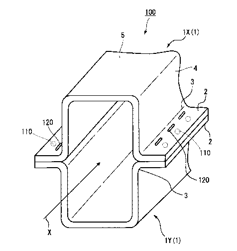
FIG. 1 is a perspective view showing a hat-shaped steel sheet member.
FIG. 2 is a perspective view showing a lap weld joint of a steel sheet
according
to a first embodiment of the present invention.
FIG. 3 is a view showing the lap weld joint and is a cross-sectional view of a
cross section that is perpendicular to a longitudinal direction and includes
an end portion
110a of a nugget 110.
FIG. 4A is an enlarged view of a portion indicated by reference symbol P in
FIG.
3.
FIG. 4B is an enlarged view of a portion indicated by reference symbol Q in
FIG. 4A.
FIG. 5 is a partial enlarged plan view of the lap weld joint.
FIG. 6 is an enlarged view of a portion indicated by reference symbol S in
FIG.
5.
FIG. 7 is a partial enlarged plan view showing a first modification example of
the lap weld joint.
FIG. 8 is a partial enlarged plan view showing a second modification example
of
the lap weld joint.
FIG. 9 is an enlarged view of the portion indicated by reference symbol S in
FIG.
and is a view showing a third modification example of the lap weld joint.
FIG. 10 is an enlarged view of the portion indicated by reference symbol S in
FIG. 5 and is a view showing a fourth modification example of the lap weld
joint.
FIG. 11 is an enlarged view of the portion indicated by reference symbol S in
FIG. 5 and is a view showing a fifth modification example of the lap weld
joint.
FIG. 12 is a perspective view showing a sixth modification example of the lap
weld joint.
FIG. 13 is a perspective view showing a seventh modification example of the
lap weld joint.
FIG. 14 is a perspective view showing an eighth modification example of the
lap
weld joint.
FIG. 15 is a partial cross-sectional view showing a lap weld joint of a steel
sheet
according to a second embodiment of the present invention.
- 6 -
CA 02994926 2018-02-06
FIG. 16A is a horizontal cross-sectional view showing a lap weld joint of a
steel
sheet of the related art and is a view for describing a lap welding method of
a steel sheet
of the related art.
FIG. 16B is a partial enlarged view of FIG. 16A.
[Embodiments of the Invention]
[0016]
Hereinafter, individual embodiments of the present invention will be described
in detail with reference to the drawings. Meanwhile, in the present
specification and the
drawings, constituent elements having substantially the same functional
constitution will
be given the same reference symbol and will not be described again.
[0017]
(First Embodiment)
FIG. 2 is a perspective view showing a lap weld joint 100 of a steel sheet
according to a first embodiment of the present invention (hereinafter, also
simply referred
to as the lap weld joint 100). The lap weld joint 100 is obtained by spot-
welding and
laser-welding a pair of steel sheet members I. In the following description,
first, the
steel sheet member 1 will be described.
[0018]
FIG. 1 is a perspective view showing the steel sheet member 1 in the lap weld
joint 100. As shown in FIG. 1, the steel sheet member 1 includes a pair of
flange
portions 2 that is long in a direction, has a hat-shaped cross section that is
perpendicular
to a longitudinal direction, and is parallel to each other, a pair of standing
wall portions 4
that substantially perpendicularly stands from the pair of flange portions 2,
and a
transverse wall portion 5 that connects the pair of standing wall portions 4
and is parallel
to the flange portions 2. The steel sheet member 1 is manufactured by, for
example,
bending a steel sheet by means of press forming. That is, in the steel sheet
member 1,
the flange portion 2 and the standing wall portion 4 are continuous with each
other, the
standing wall portion 4 and the transverse wall portion 5 are continuous with
each other,
and, particularly, there are no holes or the like formed on surfaces of the
flange portions 2,
and thus it is possible to prevent a decrease in strength.
- 7 -
CA 02994926 2018-02-06
Meanwhile, in FIG. 1, reference symbol X indicates a central axis line of the
steel sheet member 1. In addition, the direction of the central axis line X
coincides with
the longitudinal direction of the steel sheet member 1.
[0019]
The standing wall portion 4 of the steel sheet member 1 has an R portion 3
that
is connected to the flange portion 2 of the steel sheet member 1 and has a
predetermined
curvature radius. The curvature radius of the R portion 3 is, for example, 3
to 6 mm.
[0020]
The sheet thickness of the steel sheet member 1 is, for example, 0.5 to 3.2
mm.
In addition, the width (the length of the flange portion 2 perpendicular to a
sheet
thickness direction and the longitudinal direction) of the flange portion 2 of
the steel
sheet member I is, for example, 10 to 20 mm.
The component composition of the steel sheet member 1 is not particularly
limited and may be appropriately set so that mechanical characteristics
suitable for uses
can be obtained. Meanwhile, in a case in which the steel sheet member 1
contains 0.10%
by mass or more of carbon, the tensile strength significantly improves.
Therefore, the
content of carbon in the steel sheet member 1 is preferably 0.10% by mass or
more.
In addition, the steel sheet member 1 may have a surface-treated film(s)
formed
on both surfaces or on a single surface. The surface-treated film is, for
example, a
plated film, a coated film, or the like. Examples of the plated film include a
zinc plate,
an aluminum plate, a zinc/nickel plate, a zinc/iron plate, a
zinc/aluminum/magnesium
plate, and the like, and examples of a method for manufacturing plates include
hot-dip
plating, electroplating, and the like.
[0021]
Next, the lap weld joint 100 according to the present embodiment will be
described. FIG. 2 is a perspective view of the lap weld joint 100, and FIG. 3
is a
cross-sectional view of a cross section that is perpendicular to the
longitudinal direction
of the lap weld joint 100 and includes an end portion 110a of a nugget 110. As
shown
in FIG. 2 and FIG. 3, the lap weld joint 100 is long in the direction of the
central axis line
X and has a hollow cross section that is perpendicular to the central axis
line X
(longitudinal direction). In addition, the lap weld joint 100 includes a pair
of steel sheet
- 8 -
CA 02994926 2018-02-06
members 1 facing each other, a plurality of nuggets 110 that are formed by
spot-welding
flange portions 2 of the pair of steel sheet members 1, and a plurality of
weld beads 120
that are formed by laser-welding the flange portions 2 of the pair of the
steel sheet
members 1. Meanwhile, in FIG. 2 and FIG. 3, reference symbol IX indicates the
steel
sheet member 1 disposed on the upper side, and reference symbol lY indicates
the steel
sheet member 1 disposed on the lower side.
[0022]
FIG. 4A is an enlarged view of a portion indicated by reference symbol P in
FIG.
3. As shown in FIG. 3 and FIG. 4A, the nugget 110 is formed between the
flange
portions 2 by spot-welding the flange portion 2 of the steel sheet member IX
and the
flange portion 2 of the steel sheet member lY and joins the flange portion 2
of the steel
sheet member 1X and the flange portion 2 of the steel sheet member 1Y. In
other words,
the nugget 110 is formed on an overlapping surface of the flange portion 2 of
the steel
sheet member 1X and the flange portion 2 of the steel sheet member 1Y.
The weld bead 120 is formed between the flange portions 2 by welding the
flange portion 2 of the steel sheet member 1X and the flange portion 2 of the
steel sheet
member lY by radiating laser beams from the upper side of the flange portion 2
of the
steel sheet member 1X, and joins the flange portions 2 to each other. In other
words,
the weld bead 120 is formed from an external surface (among two surfaces in
the sheet
thickness direction, a surface facing the outside) of the flange portion 2 of
the steel sheet
member 1X to an inside of the flange portion 2 of the steel sheet member 1Y.
Meanwhile, the weld bead 120 may or may not penetrate the external surface of
the
flange portion 2 of the steel sheet member 1X and an external surface of the
flange
portion 2 of the steel sheet member 1Y.
[0023]
In addition, the weld bead 120 is formed in a region between an R stop 3a of
the
R portion 3 of the steel sheet member 1X and the nugget 110 as shown in FIG,
4A.
Specifically, an end portion 120a of the weld bead 120 on the inside of the
flange portion
2 in the width direction (an end portion of the weld bead 120 in the width
direction which
is closest to the R stop 3a) is located on the outside of the R stop 3a in the
width direction
in the flange portion 2. In addition, an end portion 120b of the weld bead 120
on the
- 9 -
CA 02994926 2018-02-06
outside of the flange portion 2 in the width direction (an end portion of the
weld bead
120 in the width direction which is farthest from the R stop 3a) is located on
the inside of
an end portion 110a of the nugget 110 on the inside of the flange portion 2 in
the width
direction (an end portion of the nugget 110 which is closest to the R stop 3a)
in the width
direction in the flange portion 2. Meanwhile, the end portion 120a of the weld
bead 120
may be located on the inside of the end portion 110a of the nugget 110 in the
width
direction in the flange portion 2, and the end portion 120b of the weld bead
120 may be
located on the outside of the end portion 110a of the nugget 110 in the width
direction in
the flange portion 2. That is, a part of the weld bead 120 may be formed on
the nugget
110.
[0024]
I fere, the R stop 3a will be described using FIG. 4A and FIG. 4B. Meanwhile,
FIG. 4B is an enlarged view of a portion indicated by reference symbol Q in
Fig. 4A.
As shown in FIG. 4A and FIG. 4B, the R stop 3a is a transition place from the
R portion
3 to the flange portion 2. Specifically, on a surface of the flange portion 2,
a straight
line Y1 is drawn from an end portion of the flange portion 2 toward the inside
of the steel
sheet member 1X in the width direction, and furthermore, a perpendicular line
is drawn
from an arbitrary point A on the R portion 3 of the steel sheet member 1X so
as to
intersect the straight line Yl. In addition, the point A on the R portion 3 at
which a
distance d between an intersection point B between the straight line Y1 and
the
perpendicular line and the point A reaches 0.1 mm is considered as the R stop
3a.
[0025]
As described above, the weld bead 120 is formed between the R stop 3a and the
nugget 110, and thus a distance DI (mm) between the R stop 3a and the nugget
110
becomes greater than a distance D2 (mm) between the R stop 3a and the weld
bead 120.
Meanwhile, the distance D1 refers to a distance between an intersection point
between a
perpendicular line drawn from the end portion 110a of the nugget 110 so as to
intersect
the straight line Y2 and the straight line Y2 and the R stop 3a. That is, the
distance D
is the shortest distance between the R stop 3a and the nugget 110.
In addition, the distance D2 refers to a distance between an intersection
point
between a perpendicular line drawn from the end portion 120a of the weld bead
120 so as
- 10 -
CA 02994926 2018-02-06
to intersect the straight line Y2 and the straight line Y2 and the R stop 3a.
That is, the
distance D2 is the shortest distance between the R stop 3a and the weld bead
120.
[0026]
In addition, as described above, in the lap weld joint 100, the end portion
120a
of the weld bead 120 is located on the outside of the R stop 3a in the width
direction in
the flange portion 2, and the end portion 120b of the weld bead 120 is located
on the
inside of the end portion 110a of the nugget 110 in the width direction in the
flange
portion 2, and thus the distance D1 is greater than the distance D2 (D1>D2)
and is
greater than the sum of the distance D2 and a width W (mm) of the weld bead
120
(D1>D2+W). Meanwhile, in a case in which the end portion 120a of the weld bead
120
is located on the outside of the R stop 3a in the width direction in the
flange portion 2,
and the end portion 120b of the weld bead 120 is located on the outside of the
end
portion 110a of the nugget 110 in the width direction in the flange portion 2,
the distance
D1 is greater than the distance D2 (D1>D2) and is less than the sum of the
distance D2
and the width W of the weld bead 120 (D1<D2+W).
[0027]
FIG. 5 is a plan view of the lap weld joint 100 and is a partial enlarged view
of
the flange portion 2 of the steel sheet member lx. In addition, FIG. 6 is an
enlarged
view of a portion indicated by reference symbol S in FIG. 5. As shown in FIG.
5 (that
is, in a case in which the flange portion 2 of the steel sheet member IX is
seen in a plan
view), a plurality of nuggets 110 and a plurality of weld beads 120 are
respectively
formed in series along the longitudinal direction of the flange portion 2 of
the steel sheet
member 1X. In addition, the plurality of weld beads 120 is located on the
inside of the
plurality of nuggets 110 in the width direction in the flange portion 2, and
faces the
plurality of nuggets 110 in the width direction of the flange portion 2.
[0028]
As shown in FIG. 6, in a plan view, the nugget 110 has, for example, a
circular
shape, an elliptical shape, an oval shape, or the like, and a diameter Dn
thereof is, for
example, 3-Nit to 5-Nit (mm). Meanwhile, the diameter Dn of the nugget 110
refers to the
length of the nugget 110 in the longitudinal direction of the flange portion
2. In
addition, the t (mm) represents a thinner sheet thickness between the sheet
thickness of
- 11 -
CA 02994926 2018-02-06
the flange portion 2 of the steel sheet member lx and the sheet thickness of
the flange
portion 2 of the steel sheet member 1Y.
[0029]
The weld bead 120 has a linear shape that extends along the longitudinal
direction of the flange portion 2 of the steel sheet member 1X, and a length L
(mm) (the
length in the longitudinal direction of the flange portion 2) is equal to or
greater than the
diameter Dn of the nugget 110. That is, the weld bead 120 is formed astride
both end
portions of the nugget 110 in the longitudinal direction of the flange portion
2.
Meanwhile, the length L of the weld bead 120 represents the total length of
the weld bead
120. In addition, the width W (the length in the width direction of the flange
portion 2)
of the weld bead 120 is 0.5 to 3.0 mm.
The upper limit of the length L of the weld bead 120 is not particularly
limited.
But, from the viewpoint of joint strength and torsional stiffness, the upper
limit of the
length L is preferably greater.
In addition, the width W of the weld bead 120 is preferably 0.8 to 1.5 mm, in
consideration of the efficiency of an operation for forming the weld beads.
[0030]
According to the lap weld joint 100 according to the present embodiment
described above, the weld bead 120 having the length L that is equal to or
greater than
the diameter Dn of the nugget 110 is formed in the region between the nugget
110 and
the R stop 3a of the R portion 3 of the standing wall portion 4, and thus it
is possible to
suppress torn-open deformation in the circumference of the nugget 110 against
torsional
moments around the central axis line X and tensile stress. In addition, the
width W of
the weld bead 120 is set to 0.5 to 3.0 mm, and thus it is possible to impart a
sufficient
strength for suppressing the torn-open deformation of the flange portion 2 to
the weld
bead 120. Therefore, it is possible to improve torsional stiffness and joint
strength.
[0031]
Meanwhile, regarding the distance Dl and the distance D2 shown in FIG. 4A
and FIG. 6, a ratio D2/D1 of the distance D2 to the distance D1 is preferably
1/2 or less.
In this case, the weld bead 120 comes close to the R stop 3a, and thus the
torn-open
deformation of the circumference of the nugget 110 is further suppressed, and
torsional
- 12 =
CA 02994926 2018-02-06
stiffness and joint strength can be further improved. In addition, from the
above-described viewpoint, the end portion of the weld bead 120 on the inside
in the
width direction is more preferably formed at the R stop 3a (that is, D2=0
(mm)). In this
case, it is possible to further improve torsional stiffness and joint
strength.
[0032]
Next, a lap welding method of a steel sheet according to the present
embodiment
will be described. The lap welding method of a steel sheet according to the
present
embodiment is a method for obtaining the lap weld joint 100 using the steel
sheet
members IX and 1Y. First, as shown in FIG. 2 and FIG. 3, the flange portion 2
of the
steel sheet member 1X and the flange portion 2 of the steel sheet member lY
are
overlapped with each other so that the steel sheet members 1X and lY face each
other.
[0033]
Subsequently, the flange portion 2 of the steel sheet member 1X and the flange
portion 2 of the steel sheet member lY are spot-welded in a state in which the
flange
portion 2 of the steel sheet member 1X and the flange portion 2 of the steel
sheet member
lY are overlapped with each other, thereby forming the plurality of nuggets
110 along
the longitudinal direction of the flange portion 2. At this time, the
conditions of the
spot welding and the like are not particularly limited, and, for example, it
is possible to
use a DR-type electrode having a diameter of approximately 16 mm and set the
welding
pressure to 300 to 500 kgf, the electric conduction time to 0.2 to 0.4 s, and
the electric
conduction current to 5 to 10 kA. In addition, currents may be any of direct
currents
and alternating currents, and the current waveform may be any of single-phase
current
and multi-phase current.
[0034]
In addition, regarding the diameter Dn of the nugget 110, by evaluating the
relationship between welding conditions and nugget diameters Dn to be obtained
in
advance using coupons (test pieces), it is possible to form the nuggets 110
having a
desired diameter in the steel sheet members lx and 1Y. Meanwhile, the diameter
Dn of
the nugget 110 can be evaluated by observing a cross section in the sheet
thickness
direction which includes the nugget 110.
- 13-
CA 02994926 2018-02-06
[0035]
After the flange portion 2 of the steel sheet member lx and the flange portion
2
of the steel sheet member 1Y are spot-welded together, these flange portions 2
are
laser-welded, thereby forming the plurality of weld beads 120 having the
length L that is
equal to or greater than the diameter Dn of the nugget 110 and the width W
that is 0.5 to
3.0 mm along the longitudinal direction of the flange portion 2 in the region
between the
R stop 3a of the R portion 3 of the steel sheet member lx and the nuggets 110.
[0036]
At this time, the conditions of the laser welding and the like are not
particularly
limited, but a remote laser welding apparatus is preferably used. This is
because the
remote laser welding apparatus moves the laser beam at a high speed among
welding
points using a galvanometer mirror attached to the tip end of a robot arm and
thus it is
possible to significantly shorten the operation time of welding. In addition,
as a laser
oscillator, for example, a laser such as a CO2 laser, a YAG laser, a fiber
laser, a DISK
laser, or a semiconductor laser can be used. In addition, the laser welding
can be carried
out under conditions of a laser output of 2 to 10 kW, a beam diameter on a
light focus
surface of 0.3 to 3.0 mm, and a welding rate of 0.1 to 20 m/min.
[0037]
In a case in which the steel sheet members 1X and lY are spot-welded together
as described above, due to the restrictions of the spot welding (restrictions
such as a
necessity of avoiding the contact between welding electrodes and the standing
wall
portions 4 of the steel sheet members 1X and 1Y), it is necessary to form the
nuggets 110
at locations a predetermined distance away from the R stop 3a. In contrast, in
the laser
welding, there are no restrictions as described above, and it is possible to
weld the flange
portion 2 of the steel sheet member 1X and the flange portion 2 of the steel
sheet member
lY at locations close to the R stop 3a. That is, since the flange portion 2 of
the steel
sheet member 1X and the flange portion 2 of the steel sheet member lY are
welded
together by means of laser welding, it is possible to form the weld beads 120
between the
R stop 3a of the R portion 3 of the standing wall portion 4 and the nuggets
110.
- 14 -
CA 02994926 2018-02-06
[0038]
In addition, as described above, when the steel sheet members 1X and lY are
welded together, first, spot welding is carried out. Additionally, as shown in
FIG. 4A,
in a state after spot welding and before laser welding, an uplift phenomenon
attributed to
the plastic flow of the steel sheet members 1X and lY (hereinafter, referred
to as "sheet
separation phenomenon") occurs in the circumference of the welding portion of
the
flange portion 2 of the steel sheet member 1X and the flange portion 2 of the
steel sheet
member 1Y, and, due to this sheet separation phenomenon, for example, a gap G
of 0.05
to 0.4 mm is generated between the flange portion 2 of the steel sheet member
1X and
the flange portion 2 of the steel sheet member 1Y. This gap G is relatively
uniformly
formed and thus contributes to the stabilization of welding conditions during
the laser
welding.
[0039]
That is, in a case in which the steel sheet members 1X and lY on which
galvanizing has been carried out are laser-welded together, there are cases in
which zinc
vapor generated by heating with laser beams causes the scattering (sputtering)
of molten
steel. However, even in a case in which the steel sheet members 1X and lY on
which
galvanizing has been carried out are used, during the laser welding, the gap G
of
approximately 0.05 to 0.4 mm is formed due to the sheet separation phenomenon,
and
thus the zinc vapor is discharged through the gap G, and it is possible to
suppress the
scattering (sputtering) of molten steel.
[0040]
Meanwhile, in the vicinity of the nuggets 110, the gap G is ensured due to the
sheet separation phenomenon; however, in places away from the nuggets 110,
there are
cases in which the flange portions 2 of the steel sheet members 1X and 1Y come
into
contact with each other or the gap G becomes small. Therefore, when the
distance
between the weld bead 120 and the nugget 110 is adjusted so as to be
approximately 4 to
mm, it is possible to suppress scattering, which is preferable. In other
words, in FIG.
4A, the distance D1 is preferably approximately 4 to 5 mm greater than the sum
of the
distance D2 and the width W.
- 15 -
CA 02994926 2018-02-06
[0041]
As described above, according to the lap welding method of a steel sheet
according to the present embodiment, the steel sheet members 1X and lY are
spot-welded together and then laser-welded, and thus it is possible to form
the weld
beads 120 between the nuggets 110 and the R stop 3a. In addition, the steel
sheet
members IX and lY are spot-welded together and then laser-welded, and thus,
even in a
case in which the steel sheet members 1X and lY on which galvanizing has been
carried
out are welded together, it is possible to suppress the scattering
(sputtering) of molten
steel due to the sheet separation phenomenon.
[0042]
[Modification Example of First Embodiment]
In the present embodiment, a case in which the plurality of weld beads 120 is
formed so as to face the plurality of nuggets 110 as shown in FIG. 5 has been
described.
However, as shown in FIG. 7, the weld beads 120 may be formed so as to face
every
other nugget 110. In other words, in a case in which the flange portion 2 is
seen in a
plan view, the nuggets 110 facing the weld bead 120, and the nuggets 110 not
facing the
weld bead 120 are alternately present in the longitudinal direction of the
flange portion 2.
In this case, the number of the weld beads 120 can be decreased, and thus it
is possible to
improve the efficiency of laser welding operation. Meanwhile, depending on the
number of the nuggets 110, the weld beads 120 may be formed so as to face
every two
other nuggets 110.
[0043]
In addition, as shown in FIG. 8, one weld bead 120 may be formed so as to face
all of the nuggets 110. However, compared with the modification example shown
in
FIG. 8, the present embodiment (refer to FIG. 5) is capable of further
decreasing the
thermal deformation of the steel sheet members 1X and lY caused by welding
since the
total volume of the weld beads 120 becomes smaller. In addition, in the
present
embodiment (refer to FIG. 5), in the case of being seen in the longitudinal
direction of
the flange portion 2, the plurality of weld beads 120 is formed at intervals,
and portions
having a high strength and portions having a low strength are alternately
present, and
thus it is possible to improve impact safety in a case in which the lap weld
joint 100 is
- 16 -
CA 02994926 2018-02-06
applied to automotive bodies. Therefore, from the above-described viewpoints,
the
plurality of weld beads 120 preferably faces the plurality of nuggets 110 as
in the present
embodiment (refer to FIG. 5). Furthermore, as the number of the weld beads
increases,
the stiffness of the member tends to be saturated, and thus, even when the
plurality of
weld beads 120 is provided at intervals as in the present embodiment (refer to
FIG. 5), it
is possible to obtain an effect of both joint strength improvement and member
stiffness
improvement as long as the weld beads have a length that is equal to or longer
than a
certain value.
[0044]
In addition, in the present embodiment, a case in which linear weld beads 120
are formed as shown in FIG. 5 has been described. However, as shown in FIG. 9,
a
weld bead 121 having a U shape in a plan view may be formed. In this case, it
is
possible to further relax stress concentration in end portions in which
welding begins and
ends.
In addition, as shown in FIG. 10, a weld bead 122 having a wavy shape in a
plan
view may be formed. In this case, it is possible to further increase the joint
area, and
thus it is possible to further improve joint strength.
In addition, as shown in FIG. 11, a weld bead 123 having an elliptical shape
in a
plan view may be formed. In this case, similar to the modification example of
FIG. 9, it
is possible to further relax stress concentration in end portions in which
welding begins
and ends.
[0045]
In addition, in the present embodiment, a case in which the steel sheet member
1X and the steel sheet member lY which have a hat-shaped cross section as
shown in
FIG. 2 and FIG. 3 are welded together has been described. However, as shown in
FIG.
12, the steel sheet member 1X and a planar steel sheet 10 may be welded
together.
In addition, as shown in FIG. 13, a steel sheet member 20 having one flange
portion 2, one standing wall portion 4, and one transverse wall portion 5
parallel to the
flange portion 2 may be welded to the steel sheet 10.
In addition, as shown in FIG, 14, the steel sheet member 1X and a steel sheet
member 1X' having a size different from that of the steel sheet member 1X may
be
= 17 =
CA 02994926 2018-02-06
welded together so that the flange portions 2, the standing wall portions 4,
and the
transverse wall portions 5 thereof overlap each other.
[0046]
(Second Embodiment)
Next, a lap weld joint 200 according to a second embodiment of the present
invention will be described.
[0047]
FIG. 15 is a horizontal cross-sectional view (a cross-sectional view
perpendicular to the longitudinal direction) showing the lap weld joint 200
according to
the present embodiment. In the first embodiment, a case in which the lap weld
joint
100 is constituted of two steel sheet members 1X and lY has been described. In
contrast, in the present embodiment, the lap weld joint 200 is constituted of
the steel
sheet members 1X and 1Y and, furthermore, a steel sheet member 30 having a hat-
liked
shape and a thinner sheet thickness than the steel sheet members 1X and lY as
shown in
FIG. 15.
[0048]
Regarding steel sheet components constituting automotive bodies, in steel
sheet
components made of three or more steel sheet members, there are cases in which
the
sheet thickness of the steel sheet member that is disposed on the outermost
side is thinner
than the sheet thicknesses of other steel sheet members (the case of a high
sheet thickness
ratio). In this case, nuggets that are formed by means of spot welding
propagate from
the center of the total sheet thickness, and thus, on the overlapping surface
between the
thin steel sheet member disposed on the outermost side and another steel sheet
member
disposed on the inside of the above-described thin steel sheet member, nuggets
are
incapable of easily propagating.
[0049]
As shown in FIG. 15, the lap weld joint 200 can be obtained by spot-welding
and laser-welding three steel sheet members lx, 1Y, and 30 in the same manner
as in the
lap welding method of a steel sheet according to the first embodiment. In
addition, as
shown in FIG. 15, in the lap weld joint 200, the flange portion 2 of the steel
sheet
- 18 -
CA 02994926 2018-02-06
member 1X, the flange portion 2 of the steel sheet member 1Y, and a flange
portion 32 of
the steel sheet member 30 are overlapped with one another, the nugget 110 is
formed by
spot welding, and the weld bead 120 is formed by laser welding between an R
stop 33a
of an R portion 3 and the nugget 110 on the R stop 33a side.
[0050]
In a case in which the steel sheet members having a high sheet thickness ratio
are welded together as shown in FIG. 15, there are cases in which the nuggets
110
formed by spot welding propagate from the center of the total sheet thickness
and the
nuggets do not propagate or barely propagate on the overlapping surface of the
flange
portion 32 of the steel sheet member 30 having a thin sheet thickness which is
disposed
on the outermost side and the flange portion 2 of the steel sheet member 1X
having a
sheet thickness that is thicker than the above-described sheet thickness.
However, for the lap weld joint 200, similar to the lap welding method of a
steel
sheet according to the first embodiment, spot welding and laser welding are
sequentially
carried out, and thus the weld beads 120 formed by laser welding are formed
astride the
steel sheet members 1X, 1Y, and 30. Therefore, in the lap weld joint 200, it
is possible
to obtain a sufficient joint strength even when there are portions in which
the nuggets 110
do not sufficiently propagate on the overlapping surfaces of the steel sheet
members 1X,
1Y, and 30.
[0051]
In addition, in the lap weld joint 200, similar to the case of the first
embodiment,
spot welding is firstly carried out, and thus the sheet separation phenomenon
attributed to
the plastic flow of the steel sheet members occurs in the circumferences of
the welding
portion of the flange portion 2 of the steel sheet member 1X, the flange
portion 2 of the
steel sheet member 1Y, and the flange portion 32 of the steel sheet member 30.
In
addition, a gap G is generated between these flange portions due to the sheet
separation
phenomenon. Therefore, even in the lap weld joint 200, in a case in which the
steel
sheet members 1X, 1Y, and 30 on which galvanizing has been carried out are
laser-welded together, gaps G of substantially 0.05 to 0.4 mm are formed due
to the sheet
separation phenomenon, and thus zinc vapor is discharged through these gaps G,
and it is
possible to suppress the scattering (sputtering) of molten steel.
- 19 -
CA 02994926 2018-02-06
[Examples]
[0052]
Next, examples carried out in order to confirm the effects of the present
invention will be described.
[0053]
Steel sheet members were prepared by forming steel sheets having a sheet
thickness of 1.2 mm and a tensile strength of 612 MPa into an L-like shape or
a hat shape.
In order to use as tensile test pieces, for two steel sheet members having an
L-like shape,
the flange portions thereof were overlapped with each other and spot-welded
together.
In addition, in order to use as torsional stiffness test pieces, as shown in
FIG. 2, for two
steel sheet members having a hat shape, the flange portions thereof were
overlapped with
each other and spot-welded together. In the spot welding, the flange portions
of the two
steel sheet members were interposed and pressed at a welding pressure of 4 kN
in a
DR-type electrode having a diameter of 16 mm so that nugget diameters reached
5.5 mm,
and the spot welding was carried out at an electric conduction current of 7.5
kA for an
electric conduction time of 14 cycles. In addition, the spot welding was
carried out at a
pitch of 40 mm.
[0054]
Next, the flange portions were welded together using a fiber laser in a remote
laser welding apparatus having a galvanometer mirror. In addition, regarding
the shape
and disposition of weld beads in the laser welding, the shape and disposition
of weld
beads shown in FIG. 5 were made. In addition, the width of the weld bead was
adjusted
by changing the welding rate while fixing the process point output of the
laser to 3 kW.
In Table 1, the distance D1 from an R stop to the nugget (refer to FIG. 4A),
the distance
D2 from the R stop to the weld bead, the length L of the weld bead, the pitch
P of the
spot welding, and the width W of the weld bead are shown. In addition, in each
of Test
Nos. 1 to 11, a tensile test piece and a torsional stiffness test were
produced.
- 20-
,
_______________________________________________________________________________
_____________________
Distance DI Distance 02
Length L I Pitch P t I Width W
Test from R stop from R stop to
DVD 1 of weld bead of spot welding 1-/P of weld bead
Note
No. to nugget weld bead
trnm; (mm)
(mm)
Cmm) (mm)
_______________________________________________________________________________
________________________ Cr Cli
"I
Fir '11
I 50 - - 40 -
- Comparative
a - i- ... .....,
_________________ Example -.
_
2 5.0 0 20 40
0.50 1.2 Example
.......... ... ... ______________________________ ,
3 50 .
1.0 0.20 20 40
0.50 1.2 Example
4 50 2.5 050 20 . 40
0.50 1.2 Example
,
_______________________________________________________________________________
___________________________________ 0
50 4.3 an : 20 ao 0.50! 1.2
Example .
...
6 5.0 6.0 1.20 ! 20 40
0.50 1.2 . Comparative .
.,
no
Example
,
.
7 5.0 1.0 0.20 5 40
0,13 1.2 Comparative 6'
Example
1
8 1 5.0 1.0 0.20 12 40
0.30 1.2 Example
____________________________________________________________ -I-
i
,
9 i 5.0 .
. 1.0 0.20 40 40
1.00 l
.
1.2 Example:
. ,
1., 10 50 1.0 0.20 20 40
0.50 t 0.4 Comparative
Example
t
.
1
11 5.0 1.0 0.20 20 40
0.50 1 0.8 Example
, ,
.. i
CA 02994926 2018-02-06
[0056]
In Table 1, Test No. 1 indicates a comparative example of a case in which only
the spot welding was carried out (that is, a case in which the laser welding
was not
carried out). Test No. 2 indicates an invention example of a case in which D2
was zero,
that is, the end portion of the weld bead closest to the R stop 3a was formed
on the R stop
3a. Test Nos. 3 and 4, 8 and 9, and 11 indicate invention examples of a
case in which
DI was greater than the sum of D2 and W (D1>D2+W) and the end portion 120b of
the
weld bead 120 was formed on the inside of the end portion 110a of the nugget
110 in the
width direction as shown in FIG. 4. Test No. 5 indicates an invention example
of a case
in which DI was greater than D2 (D1>D2) and was less than the sum of D2 and W
(Dl<D2+W) and a part of the weld bead was formed on the nugget.
[0057]
On the other hand, Test No. 6 indicates a comparative example of a case in
which D1 was less than D2 (DI <D2), that is, the weld beads were not formed in
a region
between the nuggets and the R stop. In addition, Test No. 7 indicates a case
in which
the diameter Dn (refer to FIG. 6) of the nugget was 5.5 mm, the length L of
the weld
bead was 5 mm, and thus L was less than Dn, that is, a comparative example. In
addition, Test No. 10 indicates a comparative example in which the width W of
the weld
bead was 0.4 mm and failed to satisfy the range (W=0.5 to 3.0 mm) of the
present
invention.
[0058]
In addition, the joint strength and the torsional stiffness of the produced
test
pieces were measured. The joint strength (the maximum load) was obtained by
pulling
out both ends of the tensile test piece using a tensile tester and breaking
the tensile test
piece. Meanwhile, the torsional stiffness was obtained by fixing one end of
the
torsional stiffness test piece and obtaining the relationship between the
torsional moment
loaded to the other end and the torsional angle measured at the other end.
[0059]
In Table 2, the joint strength, the joint strength ratio, the torsional
stiffness, and
the torsional stiffness ratio are shown. The joint strength ratio and the
torsional stiffness
22
Co CD
171-
Ch .= =
e+ 0
.
i 3'
I
Z 4
Joint strength Joint strength Torsional stiffness
Torsional stiffness `0). P co
Test No.
Note
(kN) ratio (Nm/cleg) ratio
, ,_õ-. c, -,
.
r7)3 8 .
,
--=-- i
i
KO
,
1 1.80 1.00 510 1.00
r"-Tamparative g; 573 g
Example
co ... -
2 3.39 2.12 602 1.18
Example
0 CD rm
cn
3 2.77 1.73 592 1,16
Example o., ep, 6a
- __________ _ *---- ,
__________________________________________________ .-- E.
= CO 0
V) '-`=
4 2.22 1.39 571 1.12
Example
0 ca E.
'
="^"
=.
c4
1.92 1.20 561 1.10 Example
...
co
Comparative
6 . 1.60 1.00 525 1.03
co,
Example
C-14 e- g g
_________________________________________________________________________ 7
0 0
7 1.89 1.18 551 1.08
Comparative ci.
0 ....., =-.
Example
Fo' = CD
--,,
8 2.37 1.48 = 571 1.12
Example i. 5 -6
PI) g. 3.
9 3.55 2.22 622 1.22
Example a -: =
5 u)
1.62 1.01 592
Comparative .izs L. p
, 1.16
; I
Example
___________ ---f-= ,
= P. VA
,
ci) o
11 2.42 1.51 ,
, 592 1.16
Example
= =
ye 0
EL. LI
-I
a) co
.....
_
(A
CA 02994926 2018-02-06
[0061]
In Test Nos. 2 to 5, 8, 9, and 11, the constitution of the present invention
was
fully satisfied, and thus the joint strength ratios and the torsional
stiffness ratios were
1.10 or higher. That is, it could be confirmed that, compared with Test No. 1
in which
only the spot welding was carried out, the joint strength and the torsional
stiffness could
be improved. Furthermore, in Test Nos. 2 to 4, 8, 9, and 11, it could be
confirmed that
D2/D1 was 0.5 or lower and the joint strength ratios and the torsional
stiffness ratios
became higher.
[0062]
On the other hand, in Test No. 6, the weld beads were not formed between the R
stop and the nuggets, and thus the joint strength ratio and the torsional
stiffness ratio
were lower than 1.10. In addition, in Test No. 7, the length L of the weld
bead was
shorter than the diameter Dn of the nugget, and thus the torsional stiffness
ratio was
lower than 1.10. In addition, in Test No. 10, the width W of the weld bead was
less than
0.5 mm, and thus the joint strength ratio was lower than 1.10.
[0063]
Hitherto, the embodiments of the present invention have been described, but
the
above-described embodiments are proposed as examples, and the scope of the
present
invention is not limited only to the above-described embodiments. The
above-described embodiments can be carried out in a variety of different forms
and can
be omitted, substituted, and modified in various manners within the scope of
the gist of
the invention. The above-described embodiments or modifications thereof are
included
in the scope of the invention described in the claims and equivalents thereof
as if being
included in the range or gist of the invention.
[0064]
For example, in the lap weld joints 100 and 200, the type, the component
composition, and the sheet thickness may be fully or partially identical among
the
respective steel sheet members or may be different among the respective steel
sheet
members.
24
CA 02994926 2018-02-06
[0065]
In addition, for example, in the lap weld joint 100, the disposition of the
nuggets
and the weld beads may vary in every flange portion, or it is also possible
to, in a flange
portion, divide the welding place into a plurality of sections and vary the
disposition of
nuggets and weld beads in every section.
[0066]
In addition, for example, in the modification example of the first embodiment,
a
case in which one weld bead 120 is formed astride a plurality of nuggets 110
has been
described (refer to FIG. 8). However, a plurality of weld beads 120 extending
astride a
plurality of nuggets 110 may be formed.
[0067]
In addition, for example, in the modification example of the first embodiment,
a
case in which the shape of the weld bead 123 is an elliptical shape in a plan
view has
been described (refer to FIG. 11). However, the shape of the weld bead 123 may
be a
circular shape.
[0068]
In addition, for example, in the modification example of the first embodiment,
a
case in which the steel sheet members 1X and 1X' which have a hat-shaped cross
section
are welded together has been described (refer to FIG. 14). However, a lap weld
joint
constituted of three steel sheet members may be produced by overlapping the
steel sheet
(refer to FIG. 13) to these steel sheet members 1X and 1X' from the lower side
of the
steel sheet member IX'.
[Industrial Applicability]
[0069]
According to the present invention, it is possible to provide a lap welding
method of a steel sheet and a lap weld joint which are capable of improving
joint strength
and torsional stiffness in lap weld joints that are obtained by welding a
steel sheet
member having flange portions and standing wall portions to another steel
sheet member.
[Brief Description of the Reference Symbols]
CA 02994926 2018-02-06
[0070]
1: steel sheet member
1X: steel sheet member
1Y: steel sheet member
3: R portion
3a: R stop
4: standing wall portion
5: transverse wall portion
100: lap weld joint of steel sheet
110: nugget
120: weld bead
Dn: diameter of nugget
G: gap
L: length of weld bead
W: width of weld bead
X: central axis line
26