Note : Les descriptions sont présentées dans la langue officielle dans laquelle elles ont été soumises.
CA 02995636 2018-02-14
IMPROVEMENT TO OPERATING SYSTEM OF MODULE FOR LOCKING
INJECTION DEVICES OF A SUBSYSTEM FOR APPLYING SUBSTANCES INTO
FERTILE EGGS
TERMINOLOGY
[1] Aiming at better understanding the subject matter disclosed and claimed in
the
present patent application, the meaning of some terms richly cited in the body
of the
descriptive report is shown, wherein:
[2] - Egg¨candling: is a procedure where it is checked whether the eggs are
actually
fertilized (fertile) and if they are not, they are removed from the process of
raising
chickens or the like;
[3] - Avian species: its concept refers to poultry farming that is the
breeding of
poultry for food production, especially meat and eggs. Among the species
raised in
poultry, chicken stands out. On a much smaller scale, birds are also raised
such as
turkeys, ducks, geese, quails, and ostriches.
[4] - PLC: Programmable Logic Controller is a specialized computer, based on a
microprocessor that performs control functions through software developed by
the user
(each PLC has its own software); and
[5] - HMI: Human Machine Interface.
APPLICATION FIELD
[6] The present invention patent with the title in epigraph and subject of
description
and claim in this application deals with an inventive solution with
outstanding benefits
in the segment of poultry, notably in the sector of poultry reproduction and
more
specifically in the stage of application of vaccines and or nutrients in
fertile eggs by
injection.
BACKGROUND OF THE INVENTION
[7] In view of the scope of application, the applicant, an expert in the
area of creation
and development of embryos for the creation of poultry species, after thorough
studies
of the entire classification procedure, vaccination and or nutrition and
suckling,
identified a list of emerging needs in the stage of vaccination and or
nutrition:
CA 02995636 2018-02-14
2
- optimizing the productivity of fertile eggs vaccinated and or with
nutritional
supplement;
- ensuring the efficiency of the individual intra¨egg inoculation
procedure, which is
directly related to the height of each egg in the niche of a tray;
- ensuring the operational reliability of the substance application module,
notably the
positioning matrix of the individualized height of each substance injector,
sustaining its
heights throughout the substance inoculation cycle;
- providing a significant reduction in the need for corrective maintenance
of the height
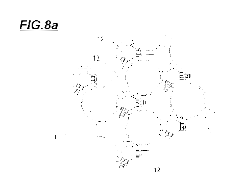
calibration device of substance injection devices, minimizing the productivity
compromise of the equipment that is dictated a priori by a production planning
and
control (PPC) routine;
- reducing maintenance costs, whether corrective or predictive, making it
faster
without compromising quality and reliability.
REQUIREMENTS OF THE INVENTION
[8] In line with the demand of the invention, the applicant has idealized the
"improvement to operating system of module for locking injector devices of a
subsystem
for applying substances into fertile eggs" provided with associated novelty of
inventive
activity, as it does not follow in an obvious or obvious way from other
anticipated
techniques by the state of the art, thus conferring advantages from the
industrial,
commercial and technical points of view.
[9] In addition, the "invention" is provided with industrial applicability,
being
economically feasible and therefore taking into account the strictness of
patentability
requirements, notably as an invention patent, according to the provisions of
articles 8
and 13 of the Law No. 9.279.
BACKGROUND OF THE TECHNIQUE
[10] In order to provide veracity, and to consolidate the explicit context in
the topics of
the introductory table, an explanation is shown on the state of the art for
the
conventional subsystems of vaccination inside fertile eggs, namely the locking
module
and stability of injection devices of substances, and, after a critical
analysis of these,
once evaluated by technicians with expertise in the subject of procedures and
operation
CA 02995636 2018-02-14
of inoculation of intra¨egg substances, will be able to identify its limiting
aspects, thus
consolidating the identification of the previously cited demand.
[11] a. Architecture of the macro system for breeding of poultry species: in
tight
synthesis, the selection, vaccination of fertile eggs and dispatch for
incubation is
performed by a non¨integrated, that is, the poultry farmer can make use of all
or only
part of its operational modules, and by acculturation, the said conventional
system is
formed by the following operational functional subsystems which are briefly
described
in the following paragraphs.
[12] a.1 Identification subsystem of fertile eggs: by which in close
understanding, the
operation of selecting fertile eggs can be done with equipment of a manual or
automated
nature. As for equipment of manual nature, the selection operation is done
with the aid
of a table that emits light under the eggs and the operator visualizes those
that allow
greater passage of light classifying them as infertile eggs. In automated
systems, there
are sensors provided with emitter and receiver of the light that passes
through the eggs.
In both situations, a human¨machine interface (HMI) management subsystem, or
alternatively a hand¨held equipment having only one table with a defined
light¨emitting
source, this subsystem acting on the incubation tray, and identifying the
niches provided
as "fertile eggs" and "non¨fertile eggs".
[13] In this way occurs the procedure of removal of the infertile eggs from
the
incubation tray, where this operation is carried out through a platform with
suction cups,
for example, and only the "fertile eggs" are kept in the incubation tray".
[14] a.2 Subsystem for the application of substances in fertile eggs: where
vaccination
and or nutrition are performed through injector devices provided with punches
and
needles for each egg housing niche defined in the incubation tray. From the
operational
point of view, once the incubation tray is positioned under the vaccination
module, the
injector matrix is activated, descending collectively and moving towards the
corresponding niches of the incubator tray, where at that moment the
computerized
system releases the dose of vaccine (or nutrients) to the needles; and
[15] a.3 Incubation subsystem of fertile eggs: after vaccination of the
fertile eggs
contained in the incubator tray, these fertile eggs are transferred to a
basket, said
delivery basket, the transfer being carried out by means of a matrix of
suction cups
disposed in matrix form, which descend simultaneously, and then vacuum is
applied
CA 02995636 2018-02-14
4
both to the suction cups corresponding to the fertile eggs and to the empty
housings.
The fertile eggs accommodated in the incubator tray are "sucked" by the
suction cups
and, in vertical movement, are transferred to the breeder's basket.
[16] b. The paradigm of the invention: After this brief introduction of the
architecture
on the selection system, vaccination of fertile eggs and incubation of fertile
eggs, for the
purpose of the present invention has chosen the subsystem of vaccination and
or
nutrition of fertile eggs.
[17] Research in patent databases reveals vaccination subsystems as
anticipated by the
state of the art, where the following patent documents deserve attention:
[18]
- US patent document US no. 6,286,455, entitled "AUTOMATED IN EGG
INJECTION APPARATUS", published on 11/09/2001, whose material reveals a
subsystem of simultaneous application of multiple substances by injection
applied to
eggs originating preferably from the egg¨candling stage.
[19] This prior art document is cited only in the light of the prior knowledge
of
subsystems for the application of substances in fertile eggs which have long
been
known, and the most commonly applied substances are vaccines, and more
recently,
nutrient administration.
[20] In a remissive way, the constructive concept of the subsystem for the
application
of substances to fertile eggs can be understood as being composed of an
accommodation
and transport device, notably a tray in which egg niches are defined in a
matrix form,
the tray is positioned immediately beneath the device with multiple injectors
of
substances, each positioned immediately above its respective egg accommodation
niche.
[21] Also, in a remissive way, each injector device has the function of
providing access
to the interior of the egg by means of a shell opening mechanism and an
injection
needle in the most varied configurations possible.
[22] In turn, from the operational point of view, once the niche parity
condition ¨
injector device is established, the module for application of substances is
actuated in
such a way that all the injecting devices are activated simultaneously,
causing activation
of the eggshell perforation mechanisms, and subsequently the injection needle
which is
the substance delivery element inside the fertile egg.
CA 02995636 2018-02-14
[23] It happens that the correct operation of the injector matrix depends on
its correct
positioning and stability in a certain Cartesian coordinate "Z", whereby for
this purpose,
an operational stability and locking module of the matrix of injecting devices
work with
two variables of control, namely:
5 [24] - the positioning on the Cartesian axis Z, which depends on the size
of the egg
disposal in the corresponding niche of each device;
[25] - the stability of the device at the position of defined Cartesian axis
Z.
[26] In order to establish this operational condition of adjustment and
stability of the
injection devices, operational modules developed for this purpose are known in
the state
of the art.
[27] Once again, research in patent databases reveal that this technology,
among
numerous patent documents, it is pertinent to mention US Patent No. 7,958,843
B2
entitled "IN EGG INJECTION MACHINE WITH TRANSVERSELY MOVABLE
EGG TRAY ASSEMBLY FOR MANUAL EGG TRANSFER AFTER INJECTION"
which, in a remissive way among so many devices, reveals a device that allows
the
adjustment of the Cartesian position Z and the lock of each injector device,
where its
constructive concept can be observed in Fig.. 7, where (...) a plurality of
injector devices
is positioned and supported in their respective plurality of openings (337) as
defined on
a support plate (332) to which inflatable elements (212) are accommodated. In
this way,
the injector device's body is passing through the inflatable elements (212)
which, once
actuated by the PLC of the equipment, begin to embrace and fix these devices
in the
Cartesian position Z previously defined by the height of the corresponding egg
niche of
the egg tray.
[28] Another document that reveals the fit and stability of the injection
devices is the
Brazilian patent document BR MU8401284 entitled "CONSTRUCTIVE PROVISION
INTRODUCED INTO AN AUTOMATIC EGG VACCINATOR", where it reveals that
(...) the injectors remain supported and guided by a platform (18) of conical
holes,
which allows the movement of the injectors in order to facilitate their
settlement on the
eggs to be vaccinated, where the injectors are fixed by means of compressed
air
bladders (16).
[29] In a remissive way, the conventional module for operating locking and
stability of
injector devices on the vertical displacement structural platform of a
functional egg
CA 02995636 2018-02-14
6
inoculation sub¨system can be described as being formed by the following
operational
modules:
- locking sub¨module, formed by the platform which has a matrix of openings
where
the respective matrix of injector devices is mounted, whereby these openings
inside the
platform are arranged diagonally or orthogonally in relation to these openings
as linear
inflatable elements, which once inflated interfere with the internal area of
the said
openings;
- a management sub¨module, formed by a PLC unit, which controls the sending of
a
signal to the control sub¨module for releasing compressed air supply to the
plurality of
inflatable elements;
- a control and release sub¨module for compressed air supply, in the form of a
3/2¨way
pneumatic valve;
- a safety sub¨module, formed by a quick release valve, so that the system can
rapidly
depressurize when necessary.
[30] In turn, from the operational point of view, this conventional system can
be
described by the PLC to send a signal to the pneumatic valve that releases the
compressed air to the locking platform, from that moment the PLC counts a time
for the
system to pressurize and release the signal to activate the injectors.
[31] c. Identification of problems: although the stability and locking modules
of
injectors disclosed in cited patent document US No. 7,958,843 B2 entitled
"IN¨EGG
INJECTION MACHINE WITH TRANSVERSELY MOVABLE EGG TRAY
ASSEMBLY FOR MANUAL EGG TRANSFER AFTER INJECTION" and BR
MU8401284 entitled CONSTRUCTIVE PROVISION INTRODUCED IN
AUTOMATIC VACCINATOR OF EGGS are effective in meeting their main objective,
the careful observation by experts in the area of fertilization and
development of poultry
embryos reveals a problem considered as critical, which can be outlined by the
occurrence of operational defects related to the locking and stabilization
sub¨module.
[32] When a defect occurs in the locking and stabilization sub¨module, the
module for
inoculation of substances continues to operate in its other functions, notably
in drilling
and injection operations; however, due to the positional instability caused by
said
defect, the substance begins to be incorrectly inoculated intra¨egg, thereby
CA 02995636 2018-02-14
7
compromising one or more inoculation cycles such as vaccination, for example,
thus
obtaining batches of poorly immunized and/or nourished fertile eggs.
[331 In turn, once the failure of the locking and stabilization sub¨module is
established,
it is also verified that the maintenance of the same is difficult to execute,
given the
constructive concept of inflatable elements that are mounted inside the
vertical
displacement platform, which means high dismantling time of the platform with
corresponding increased machine downtime and also high labor costs for repair
intervention.
[34] d. Cause for the identified problems:
[35] Defects in the locking and stabilization sub¨module with the constructive
concepts described in advance by the state of the art are due to insufficient
pressurizing
of the inflatable elements that embrace and stabilize the injection devices,
due to non¨
unusual leaks in the structure of these inflatable elements, and it is
possible to list a list
of causes for this to occur which deserves attention:
- its operation is dependent on the continuous and stable supply of compressed
air so as
to promote the activation of the inflatable elements and locking of the
injectors.
- there is no control ensuring that the necessary pressure is constant for the
correct
operation of the inflatable elements, especially in the case where air leakage
is detected
by the elements. Failure to obtain sufficient pressure on the inflatable
elements in order
to obtain the clamping effect of the injector devices will result in a gap in
the platform
housings and, consequently, the injector device will move during the drilling
leading to
non¨conformities such as cracking of the eggshell, deformation, and disuse of
the
injection needle and, further, death of the embryo by needle perforation of
its vital
organs.
[36] Finally, referring to the problem of complexity of the maintenance
activity, its
cause is explained by the complexity of the constructive concept of this
device that
confers difficulty in disassembling the same.
DESCRIPTION OF THE INVENTION
[37] a. Objective: it is an object of the present invention to solve the
causes of the
problems previously listed in the topic of technology fundamentals of the art
by
presenting an improvement in operating system, of the injector device locking
device of
CA 02995636 2018-02-14
8
a subsystem of application of substances in fertile eggs, which adds value to
the
conventional subsystem, wherein a remissive way such improvement confers the
following predicates:
- to control and define the measurement of the compressed air pressure
applied to the
inflatable elements;
- to adjust the injector devices operation only if the handling stability of
the injector
devices + [inflatable] handle elements couple is guaranteed, through the
correct supply
of compressed air;
- only if the injector devices are actuated after the stabilization of the
pressure in a
suitable range;
- to generate feedback to the parameter management system of "pressure
level"
parameter, allowing the control unit to block the operation in case of an
identified
defect, such as air leakage, for example; Facilitate the maintenance and
consequently
reduce the machine downtime.
[38] b. Distinctive feature
[39] b.1 Constructive concept:
[40] The locking and stability module of the substance injector devices
consists of:
- a sub¨module for locking injector devices, which in turn is composed of a
vertical
displacement platform which is to be manufactured from a single part, which
receives a
plurality of standard openings, through which is passing the body of each
substance
injector device, wherein adjacent to each opening is defined an assembly of at
least
three adjacent openings, which purpose is to provide the assembly of
inflatable
elements.
[41] All the inflatable elements are communicating with each other by means of
communication tubes, through which the compressed air is supplied.
- Management sub¨module, wherein the sending of the compressed air to the
plurality
of inflatable elements mounted on the vertical displacement platform is
defined by a
PLC controller.
- pressure recognition sub¨module, wherein the pressure reading in the
plurality of
inflatable elements is defined by a pressure transmitter;
- safety sub¨module, in order to provide a safe equipment operation a quick
release
valve is provided so that the system depressurizes quickly when necessary,
emptying
CA 02995636 2018-02-14
9
the cartridges or bladders as fast as possible to make the machine cycle fast
and it can
proceed to the next step;
- a control and release sub¨module for compressed air, where the release of
the supply
of compressed air to the matrix of inflatable elements mounted on the platform
of
vertical displacement is carried out by a 3/2¨way pneumatic valve;
[42] b.2 Functional concept: the improved injector device lockout module
operating
system of a sub¨system for applying substances to fertile eggs has operational
logic by
sending a signal via the operational management sub¨module, in the form of a
PLC
command to a sub¨module controlling the release of compressed air in the form
of a
3/2¨way valve, which in turn releases the compressed air to the vertical
displacement
platform where the injector devices of substances are mounted and stabilized,
and in
turn, a sub¨module identifying the compressed air supply stability is provided
in the
inflatable element matrix, in the form of a pressure transmitter, or
alternatively a flow
meter, which in turn sends a return signal to the sub¨module in the form of a
PLC
command where it waits for a certain level of pressure to be obtained to
ensure that all
injector devices are embraced by the inflatable elements, so that only this
condition
enables the operation of the plurality of devices injectors, thus ensuring its
operational
effectiveness.
DESCRIPTION OF THE FIGURES
[43] Complementing the present description in order to obtain a better
understanding
of the features of the present invention, and according to a preferred
practical
embodiment thereof, the attached description is accompanied by a set of
drawings,
wherein:
- Fig. 1 is an illustrative representation in perspective of the constructive
concept of the
fertilizing egg application module anticipated by the state of the art, with
reference to
Fig. 2 of U.S. Patent No. 6,286,455, showing the main component parts, notably
the
vertical movement platform where is located the improvement in operating
system of
the module for locking injecting devices of a sub¨system for application of
substances
in fertile eggs;
- Fig. 2 is an illustrative representation in late view of the constructive
concept of the
module for adding substances to fertile eggs anticipated by the state of the
art, with
CA 02995636 2018-02-14
reference to Fig. 1 of the U.S. patent document No. 6,286,455, showing the
main
components parts, namely the vertical movement platform where the improvement
of
the operative system of locking modules of injector devices of a sub¨system of
application of substances in fertile eggs is located;
5 - Fig. 3a is an illustrative representation of the architecture of the
conventional module
for activation and locking of injector devices in the vertical movement
platform of a
sub¨system of application of substances in fertile eggs, as anticipated by the
state of the
art;
- Fig. 3b is an illustrative representation of component parts of each
operating sub-
10 module from the conventional module for driving and locking injector
devices on the
vertical movement platform of a sub¨system for application of substances in
fertile
eggs, as anticipated by the state of the art;
- Fig. 4a is an illustrative representation of the architecture of the
improved drive and
locking module of injector devices in the vertical movement platform of a
subsystem of
application of substances in fertile eggs, as anticipated by the state of the
art;
- Fig. 4b is an illustrative representation of component parts of each
sub¨module of the
improved module for actuating and locking injector devices on the vertical
movement
platform of a sub¨system for applying substances in fertile eggs, as
anticipated by the
state of the art;
- Fig. 5a is an illustrative perspective view of the constructiveness of the
locking device
of the injector devices of the locking sub¨module of the improved drive and
locking
module, showing its component parts;
- Fig. 5b is an illustrative representation in view of raising the
constructiveness of the
locking device of the injector devices of the locking sub¨module of the
improved drive
and locking module, showing their component parts;
- Fig. 6a is an illustrative representation in view of the elevation of the
constructiveness
of the mounting platform part of the locking device of the injector devices,
showing
their component parts;
- Fig. 6b is an illustrative representation in elevation view of an enlarged
detail of the
mounting bracket part of the locking sub¨module of the improved locking drive
module, showing its constructiveness;
CA 02995636 2018-02-14
11
- Fig. 7a is an illustrative perspective view of the inflatable element
part of the locking
device of the locking sub¨module of the improved drive and locking module,
showing
its external constructiveness;
- Fig. 7b is an illustrative side view of the inflatable element part of
the locking device
of the locking sub¨module of the improved locking and drive module, showing
its
external constructiveness;
- Fig. 7c is an illustrative representation of longitudinal cross¨sectional
view of the
inflatable element part of the locking device of the locking sub¨module of the
improved
drive and locking module, evidencing its external constructiveness;
- Figs. 8a and 8b are enlarged detail representations of elevation and
perspective views
of the locking device of the locking sub¨module of the improved actuation and
locking
module, in a condition immediately prior to the activation of system
pressurization; and
- Figs. 9a and 9b are enlarged detail representations of elevation and
perspective views
of the locking device of the locking sub¨module of the improved actuation and
locking
module, in a condition immediately prior to system activation.
DETAILED DESCRIPTION
[44] The following detailed description should be read and interpreted with
reference
to the drawings shown and are not intended to limit the scope of the
invention, but only
limited to this explained in the claims.
[45] a. State of the art:
[46] a.1 Understanding the field of application: as shown in Figs. 1 and 2,
the
conventional application subsystem of substances in fertile eggs (Et) is
composed
essentially of the devices:
- displacement module of the egg tray: formed by a horizontal displacement
platform
(Ph) which has the function of providing the displacement and positioning of
the tray
(b), and aligned with the matrix of injector devices (d);
- egg accommodating module: in the form of a tray (b), provided with a
plurality of
niches (bl) where the fertile eggs are accommodated (0v);
- injector locking and stability module: in the form of a vertical
displacement platform
(Pv) which has the function of providing the assembly and stabilization of the
injector
matrix (I), also providing the vertical displacement of such matrix;
CA 02995636 2018-02-14
12
- injection module: in the form of a plurality of injector devices (I) for
the purpose of
providing an injection of substances, notably vaccines and nutrients;
[47] As previously defined, the locking and displacement module of
conventional
injectors were chosen as the development paradigm.
[48] a.2 Technological basis
[49] As shown in Figs. 3a and 3b, the locking and displacement module of
conventional
injectors shown in a remissive form displays the following architecture of
operating
sub¨modules:
- a locking sub¨module (ml), formed by the platform (11) having a matrix of
openings
(12) wherein the respective matrix of injector devices (I) is mounted, wherein
to these
openings (12), a set of linear inflatable elements within the platform is
disposed
diagonally or orthogonally to these openings, which once inflated interfere
with the
internal area of said openings (12);
- a management sub¨module (m2), formed by a PLC unit (21), which controls
the
sending of the signal to the control and release of compressed air sub¨module
(m3) to
the plurality of inflatable elements;
- a control and release of compressed air sub¨module (m3), in the form of a
3/2¨way air
valve (31); and
- a safety sub¨module (m4), formed by a quick release valve (41), so that
the system
will rapidly depressurize when necessary.
[50] b. Introduced improvements
[51] b.1 Operating system Improvement: As shown in Figs. 4a and 4b, the
improved
locking and displacement module of injectors shows, in a remissive manner, the
measured architecture of sub¨modules of the conventional module, by adding a
sub-
module identifying the compressed air supply stability (m5), which can be done
by
reading the pressure in the plurality of inflatable elements (12), wherein
this case it is
defined by a pressure transmitter (51).
[52] Alternatively, the sub¨module identifying the compressed air supply
stability
(m5) may be specified by performing the reading of the compressed air flow in
the
circuit, wherein this case it is defined by an air flow meter (52).
[53] b.2 Improvement of the locking sub¨module (m1): as shown in Figs. 5a and
5b, it
is composed of: a platform (11) onto which a plurality of inflatable elements
(12) is
CA 02995636 2018-02-14
13
mounted which in turn are connected by segments of connector tubes (13) to
configure
a closed loop system.
[54] b.21 Platform (11): which detail is shown in Figs. 6a and 6b, composed of
a single
body (I la) receiving a plurality of standard openings (11c) through which the
body of
each substance injector device (I) passes and, adjacent to each opening (11
c), a set of at
least three adjacent openings (11b) is defined, which has the function of
providing the
assembly of inflatable elements (12);
1551 b.22 Inflatable elements (12): as shown in Figs. 7a, 7b and 7c
respectively,
wherein in a form of embodiment is defined a flexible tubular body (12c) whose
upper
and lower ends receive covers (12b) and (12a) respectively, the latter of
which receives
connecting terminals (12d) with the function of assembling where segments of
connector tubes (13) are attached.
[56] In turn, the inflatable elements (12) are mounted in the respective
adjacent
openings (1 1 b) defined in the platform (11).
[57] b.23 Connector tubes (13): all the inflatable elements (12) are
communicating
with each other by means of connector tubes (13), through which compressed air
is
supplied.
[58] c. Operating logics: By means of a PLC command (21) of the operational
management sub¨module (m2) a signal is sent to the 3/2¨way valve (31) of the
control
and release of compressed air sub¨module (m3) which in turn releases the
compressed
air in a constant and stabilized way through the connector tubes (13), which
fill the
plurality of inflatable elements (12), creating internal pressure leading to
the expansion
of the flexible tubular body (12c), which in turn starts to compress the body
of the
injector device (I), promoting its locking and stability, as shown in Figs. 9a
and 9b.
[59] Once the condition for locking and stability of the injector device (I)
is obtained,
the internal pressure of the system formed by the plurality of connector
elements (12) is
measured by the pressure transmitter (51) of the pressure recognition
sub¨module (m5),
which sends the data obtained, in a signal form, to the PLC command (21) of
the
operational management sub¨module (m2), which in turn, makes the comparative
parity
of that value with a predetermined pressure value (or a range of values)
previously
defined at the time the operating system of the locking and displacement
module of
injectors was calibrated. If the measured pressure value is lower than the
previously
CA 02995636 2018-02-14
14
measured standard value, the PLC command (21) of the operational management
sub¨
module (m2) truncates the operational initiation of the substance inoculation
module,
thus avoiding erroneous vaccination and/or nutrition procedures previously
described in
the topic of principles of the technique.
[60] If the pressure value measured by the pressure transmitter (51) of the
pressure
recognition sub¨module (m5) is equal to or greater than the specified value,
the PLC
command (21) of the operational management sub¨module (m2) initiates the
operation
of the substance inoculation module.
[61] d. The obtained technical effect:
[62] d.1 Locking and stabilization guarantee: as shown in Figs. 8a and 8b in
an
accommodating condition of the injector devices (I) in their respective
standard
openings (11c) further showing the assembly of the inflatable elements (12),
showing
that there is a gap (F) in a condition immediately prior to receiving
compressed air by
these inflatable elements (12).
[63] In turn, once the locking and stability module of the injectors is
activated, the
technical effect is revealed through Figs. 9a and 9b, where it is visible the
expansion of
the walls of the flexible tubular body (12c), configuring the locking of the
injectors (I),
which guarantees the operational integrity of the subsystem of application of
substances
in fertile eggs.
[64] d.2 Ease of maintenance of the locking sub¨module: in the case of
perforation of
any one of the inflatable elements (12), the exchange operation of the same is
easy to
perform, by locating those non¨conforming elements, disconnecting the ends of
the
connector tubes (13), withdraw them from the adjacent openings (1 1 b) which
support
them in the body (11 a) of the platform (11), and then replace them with a
functional
inflatable element (12).
[65] The choice of the preferred embodiment of the subject invention in this
carton,
described in this detailing topic, is provided by way of example only.
Changes,
modifications, and variations can be made to any other embodiment of the
operating
system with the introduction of a pressure recognition sub¨module (m5), and
the
improvement of the locking module (m1) of the subsystem for the application of
substances to fertile eggs, whereby such changes may be designed by those
skilled in
CA 02995636 2018-02-14
the art, however, without departing from the disclosed object in the present
patent
application, which is defined exclusively by the appended claims.
1661 It is seen from what has been described and illustrated that the
"IMPROVEMENT
TO OPERATING SYSTEM OF MODULE FOR LOCKING INJECTOR DEVICES OF
5 A SUBSYSTEM FOR APPLYING SUBSTANCES INTO FERTILE EGGS" herein
claimed conforms to the norms governing the patent of invention in light of
the
Industrial Property Law, deserving of what was exposed and as a consequence,
the
respective privilege.