Note : Les descriptions sont présentées dans la langue officielle dans laquelle elles ont été soumises.
CA 02996815 2018-02-27
SEED DRILL COULTER ARRANGEMENT OF AN
AGRICULTURAL MACHINE AND SEED DRILL COULTER
THEREFOR
The present invention relates to a sowing coulter arrangement of an
agricultural
machine for soil tillage and/or for spreading materials to be distributed,
such as seeds, fertilizer,
or the like, the arrangement having the features of the independent claim 1.
Seed drill coulters or sowing coulters, such as double-disk coulters, single-
disk coulters,
or tine coulters, are known from the prior art in the most diverse of
embodiment forms. Such a
sowing coulter is disclosed in EP 2 022 307 B1, for example. The disclosed
sowing coulter is
used with an agricultural single-grain sowing machine. Arranged at a coulter
frame, there is at
least one coulter disk to serve as furrow-opening unit and therebehind is a
seed tube with an
associated catching roller and a subsequent pressure roller. In order to
facilitate assembly and
maintenance of the seed tube, it is provided that the seed tube, the catching
roller, and the
pressure roller are disposed as a unit on a coulter frame in a detachable
and/or swing-away
manner. In order to ensure that the material to be distributed is optimally
dispensed from a seed
tube into a seed furrow, the outlet of the seed tube is moreover disposed such
that the seed
flow is aligned tangentially to the circumference of the catching roller. The
catching roller is
followed by a pressure roller, by means of which the distributed material is
pressed into the
soil. The catching roller and the pressure roller are affixed together on one
common pivotable
carrier, resulting in the disadvantage that shocks and impacts or vibrations
acting upon the
sowing coulter and being caused by bumpy ground, for example, are in each
instance
transmitted from the catching roller onto the pressure roller and vice versa,
thereby impairing
the required even dispensing of the material to be distributed.
DE 2 934 121 C2 shows another sowing coulter. This coulter consists of a
furrow opener
with a following pressure roller. The furrow opener can be designed, for
example, as a tine
coulter or the like. The pressure roller moreover serves both for depth
control and as a catching
element. Following a metering device or a separating device, the material to
be distributed is
dispensed into a seed tube. The material to be distributed is subsequently
pneumatically
accelerated in the seed tube. The outlet of the seed tube is disposed in such
a manner that the
CA 02996815 2018-02-27
- 2 -
seed flow forms an angle bisector between a ground surface and a tangent to
the pressure
roller. In this way, it is intended that the material to be distributed, which
has been accelerated
by the seed tube, is slowed down and that the distributed material is
prevented from undesired
bouncing or undesired rolling in the seed furrow. However, the pressure roller
can move
independently of the seed tube outlet, thus partly impairing the desired
arrangement and the
described effect.
WO 2011 119 095 Al shows a further seed drill coulter for a single-grain
sowing
machine. This seed drill coulter or sowing coulter has a pneumatically
operated seed tube
arranged on the side of at least one coulter disk. The outlet of the seed
tube, or, as the case
may be, the seed flow at the outlet of the seed tube, is directed such that it
forms a tangent to
a circumference of a catching element, preferably of a catching roller. The
catching roller and
a pressure roller following it are affixed together on one common coulter
frame, with the
pressure roller in turn being mounted to be pivotable in relation to the
coulter frame. The
catching roller and the pressure roller are thus decoupled from one another.
The seed tube or,
as the case may be, the metering device, is likewise decoupled from the
catching roller, which
in turn leads to the tangential arrangement not being permanently ensured, and
thus to a
negative influence on the dispensing of the material to be distributed. The
dispensing quality
can be moreover improved or impaired depending on the nature of the ground or,
more
precisely, on impacts and vibrations, which lead to the distribution precision
not being steadily
and evenly ensured.
Therefore, although numerous diverse sowing coulters are known from the prior
art that
in each instance have a seed tube, a catching element, and a pressure roller,
they nevertheless
do not permanently ensure a defined arrangement of a seed tube in relation to
a catching roller,
and thus it is not possible to achieve a consistent distribution precision.
The sowing coulters with a metering device for single-grain metering as have
become
known from the prior art are usually affixed to an agricultural machine via a
so-called
parallelogram linkage. The advantage thereof is that the sowing coulter can
move parallel to a
ground surface at all times, independently of its working depth. Moreover,
such sowing coulters
are generally designed as so-called double-disk coulters, that is to say that
in each case two
cutting disks disposed at an angle in relation to one another create one seed
furrow. Such
parallelogram linkages, however, require an elaborate and costly input of
parts. In addition,
CA 02996815 2018-02-27
- 3 -
each of the parallelogram linkages has very many pivot points, resulting in
very high-
maintenance sowing coulters. Furthermore, such double-disk coulters are only
suitable to a
limited extent for direct drilling in particular, since great forces are
required for the two cutting
disks to penetrate into the soil.
So-called single-disk coulters present an alternative to such double-disk
coulters with
parallelogram linkage. EP 0 956 755 Al, for example, describes a single-disk
coulter. Single-
disk coulters are generally affixed to an agricultural machine via a central
pivot point. Also, the
seed furrow is created by only one cutting disk that is disposed at an angle
to the driving
direction. Suchlike sowing coulters are, in particular, used for direct
drilling, that is, for placing
the seeds into unprepared soil. It is not yet possible, however, to mount a
metering device for
single-grain metering on such sowing coulters with a central pivot point. This
is due to the fact
that even a slight depth adjustment of these sowing coulters has a great
impact on the position
between seed tube and seed furrow and accordingly on the position between seed
tube and
catching roller. Particularly the angle positions are greatly influenced in
this context so that
precise seed placement cannot be ensured with different sowing depths.
The underlying task of the invention is therefore seen in creating a sowing
coulter or, as
the case may be, a sowing coulter arrangement, of an agricultural machine with
an improved
arrangement of a metering device, a seed tube, and a catching element relative
to each other
as well as in relation to a pressure roller or to a furrow-closing element,
whereby an
arrangement of a seed tube outlet relative to a catching element is at all
times kept largely
constant. The improved arrangement according to the invention is intended for
ensuring that
the material to be distributed is steadily and evenly dispensed from a seed
tube into a seed
furrow.
This task is fulfilled by the teachings of claim 1, with features that further
the
development of the invention in an advantageous manner being presented in the
following
claims.
The present invention thus proposes a sowing coulter arrangement, for example
with a
single-disk coulter or a double-disk coulter, for soil tillage and/or for
spreading materials to be
distributed, such as seeds, fertilizer, or the like. The sowing coulter
arrangement has at least a
suspension device for mounting the sowing coulter arrangement on a frame
structure. The
sowing coulter arrangement according to the invention further comprises a
coulter frame, on
CA 02996815 2018-02-27
- 4 -
which the components of the sowing coulter or, as the case may be, the
components of the
arrangement, can be mounted. For the purpose of creating a seed furrow, at
least a rotatably
disposed coulter disk or a tine implement is mounted on the coulter frame. The
particular
material to be distributed is placed in the seed furrow. Furthermore, a
rotatably disposed depth
control roller can be mounted on the coulter frame, by means of which depth
control roller the
depth adjustment of the coulter disk and accordingly of the seed furrow is
carried out. A
pressure roller for pressing the distributed material into the soil and for
closing the seed furrow
can be pivot-mounted and/or tandem-mounted on the coulter frame and arranged
so as to
follow the coulter disk that is at least present, or, as the case may be, the
tine implement. For
the purpose of closing the seed furrow, it is also conceivable that, for
example, a harrow or the
like broaching tool is or, as the case may be, are affixed to the coulter
frame to serve as furrow-
closing element/s.
The sowing coulter arrangement according to the invention further comprises a
metering device for the at least to a large extent separated or, as the case
may be, evenly
dispersed dispensing of the material to be distributed, as well as a seed tube
arranged
downstream of or associated with said metering device. The seed tube can be
disposed
laterally from a coulter disk or, as the case may be, centrally between two
coulter disks, or
behind the tine implement. The seed tube outlet preferably ends in an area
immediately above
a ground surface or, as the case may be, above the seed furrow. A catching
element is
preferably arranged downstream of the seed tube outlet. Said catching element
is preferably
located next to at least one coulter disk or, as the case may be, between the
two coulter disks,
or behind the tine implement and in front of the pressure roller or, as the
case may be, in front
of the furrow-closing element. The seed tube outlet is directed such that a
seed flow is
generated that can form, for example, a tangent to a circumference of the
catching element or,
as the case may be, of the catching roller. In this manner, the catching
element is intended to
slow down the distributed material in the seed furrow and to protect it
against undesired rolling
and undesired bouncing, thereby achieving an improved dispensing of the
distributed material
in the seed furrow. In order to ensure at all times that this is carried out
independently of
movements of the catching element and/or of the pressure roller, as well as
independently of
the working depth, at least the metering device, the seed tube, and the
catching roller form a
unit and are mounted together on one common carrier, with the carrier being
preferably pivot-
mounted or, as the case may be, pivotably connected to a coulter frame or to a
frame structure
of an agricultural machine via an axle or by means of a parallelogram linkage.
The carrier can
CA 02996815 2018-02-27
- 5 -
thus move independently of the pressure roller. On the one hand, for example,
a tangential
arrangement between seed flow and catching element is at all times ensured in
this way, and
on the other hand, it is ensured that movements of the catching element are
not transmitted to
the coulter frame or to the pressure roller and vice versa. Shocks,
vibrations, or the like thus
no longer have an influence on the dispensing of material to be distributed.
The mentioned unit formed by at least the metering device, the seed tube, and
the
catching roller, can, in particular, refer to an assembly or to a unit that is
structurally integrated
and/or to a unit the elements of which form an operative connection between
each other, with
the unit being mounted on the common carrier.
Particularly with sowing coulters that are connected to an agricultural
machine via a
central pivot point, it is thus possible to achieve a permanently constant
distribution precision,
since changes of the angle position of the sowing coulter no longer have an
influence on the
position between seed tube and catching element. This can be further improved,
in particular,
if the carrier of the metering device, the seed tube, and the catching element
is connected to
the coulter frame or to the agricultural machine via a parallelogram linkage.
Besides the metering device, the seed tube, and the catching roller, it is
moreover
conceivable in a further embodiment that the furrow opener, which is likewise
present on a
sowing coulter, in particular on a single-disk coulter, also forms a part of
said unit and is also
mounted to the carrier or, as the case may be, to the seed tube.
In addition to a seed flow alignment that is tangential to the circumference
of the
catching element, it is also conceivable that the seed flow forms an angle
bisector or a line
disposed between the ground surface and a tangent to the circumference of the
catching
element. In this instance, the tangent to the circumference of the catching
element encloses an
angle in relation to the ground surface, with said angle being less than 75 ,
in particular less
than 60 , and preferably less than 45 . This in turn results in slowing down
the material to be
distributed and in preventing undesired bouncing or undesired rolling.
The arrangement of the seed flow is preferably aligned such that the seed flow
is cut off
or, as the case may be, interrupted by means of the catching element, whereby
the material to
be distributed is slowed down and undesired rolling and undesired bouncing of
the distributed
material in the seed furrow is prevented.
CA 02996815 2018-02-27
- 6 -
Connecting the carrier to, for example, the coulter frame or the frame
structure of an
agricultural machine by means of a parallelogram linkage or a four-joint
arrangement moreover
has the advantage that an angle between seed flow and ground surface is at all
times largely
constant, independently of the working depth. It is likewise conceivable that
the suspension
device of the sowing coulter forms a parallelogram linkage. It is further
conceivable that both
the suspension device and the connection between coulter frame and carrier
form a
parallelogram linkage. Generally, the most diverse of suspension devices and
connections are
thus conceivable, with these being in each case designed such that a relative
arrangement
between a seed tube outlet and a catching element can be at all times kept
constant
independently of movements of the sowing coulter.
In a further embodiment variant, it is conceivable that the coulter disk and
the carrier
are pivot-mounted together on one common pivot point or, as the case may be,
on one common
axle.
The carrier can be preloaded by way of a spring element in relation to the
ground
surface or, as the case may be, in relation to the seed furrow. For example, a
pressure spring,
a hydraulic or pneumatic actuator, or the like can be used as a spring
element. Other spring
elements are also conceivable. The preload is intended for guiding the unit of
seed tube and
catching element in a constant manner in the seed furrow. Preferably, however,
the preload is
selected such that a movement of the carrier is still possible, for instance
when driving over
stones. Said preload or, as the case may be, said spring option additionally
has the advantage
that the catching element can be made from, for example, a hard material, such
as a metallic
material or a synthetic material or a composite material, which materials are
substantially more
durable and cheaper than elastic materials. Elastic materials are, however,
also conceivable,
for example elastic synthetic materials or composite materials or rubber
materials, with the
effect that preloading the carrier could be omitted when using such materials.
Designing the
catching element from elastic material would moreover have the advantage that
a further
cushioning against shocks and impacts would be carried out by means of the
elastic catching
element, thereby in turn preventing a negative influence on the entire
dispensing process of
the material to be distributed. It is also conceivable to preload only the
catching element toward
the seed furrow by means of a spring.
CA 02996815 2018-02-27
- 7 -
A metering device is associated with the sowing coulter. This metering device
makes it
possible to separate, at least to a large extent, the particular material to
be distributed, for which
separation it is possible to use different separating methods that are known
from the prior art.
The metering device can operate based on the principle of differential
pressure and/or on the
principle of centrifugation, for example. Preferably, the metering device can
operate based on
the principle of positive pressure, and it can have, in particular, the
features as described in the
German patent application 10 2015 101 253.7. The metering device could equally
operate
based on the principle of centrifugation and have the features as described in
the German
patent application 10 2012 105 081.3 or in the German patent application 10
2012 105 048.1.
Mechanical metering devices are conceivable as well.
The material to be distributed can undergo an active acceleration in the
metering device
and/or in the seed tube. This can be carried out, for example, by means of a
separating disk
rotating inside the metering device, or by means of a differential pressure
prevailing between
the housing of the metering device and the seed tube outlet. Pneumatic
nozzles, for example
a ring nozzle or the like, can be applied, too. The material to be distributed
is conveyed through
the seed tube by the acceleration at a speed that is preferably greater than
the acceleration of
gravity. The intention behind this acceleration is that shocks and vibrations
do not influence the
transport of the material to be distributed that is located in the seed tube.
It is also conceivable that the seed tube includes a conveyor belt, that is to
say that the
material to be distributed is not conveyed through the seed tube by means of
gravity or airflow,
but that a conveyor belt receives the material to be distributed from the
metering device and
transports it downward to the seed furrow.
The coulter frame can be designed either in one piece or in multiple pieces.
The coulter
frame could thus have a coulter tube, for example, to which various different
mounting plates
or mounting elements or the like can be affixed. In addition, the coulter tube
could be
manufactured by casting or forging. Bearing elements or parts of the
suspension device could
also be integrated into the coulter tube or, as the case may be, into the
coulter frame.
Said suspension device can likewise be designed in various different ways,
while said
suspension device in each case serves to connect the coulter frame or, as the
case may be,
the sowing coulter, to a frame structure of an agricultural machine. The
suspension device
could thus be pivotably connected to the frame structure by way of a swivel
axle or, as the case
CA 02996815 2018-02-27
- 8 -
may be, by way of a central pivot point. For this purpose, the swivel axle
could also be equipped,
for example, with a rubber cord bearing as known from the prior art. The
suspension device
could have a parallelogram linkage, too. A rigid or fixed connection between
sowing coulter and
frame structure is conceivable, while pivotable or movable connections are,
however,
preferably used.
The pressure roller and/or the catching element and/or the depth control
roller could
furthermore each be realized with the same roller, with the result that not
three rolls or elements
would be required, but only one roll or element, thus substantially reducing
the input of parts.
That is to say that when the components of the sowing coulter arrangement
according to the
invention are listed and several functional elements are referred to, these
are not necessarily
to be understood to imply separate components. In fact, it is possible to
combine several
functions and to have them fulfilled by one or two components.
The depth control roller can moreover be mounted on the sowing coulter in many
different positions. For example, it can be mounted, at least in sections,
next to the coulter disk
or, as the case may be, next to the tine coulter and/or, at least in sections,
next to the catching
element. It can equally be mounted behind the coulter disk or, as the case may
be, behind the
tine coulter, and behind the catching element, in which embodiment the depth
control roller can
also form the pressure roller.
The present invention is particularly suitable for use in so-called single-
disk coulters.
These sowing coulters are usually used for direct drilling, that is to say
that they are used for
spreading the material to be distributed in unprepared soil. For achieving an
adequate
distribution precision, however, this type of sowing makes high demands on the
sowing
coulters, since the unprepared ground can lead to particularly pronounced
vibration effects.
Only by arranging the seed tube and the catching element according to the
invention together
on one common carrier does it thus become realizable to use a metering device
in a single-
disk coulter and achieve a consistent distribution quality at the same time.
Mostly, the "sowing coulter arrangement" according to the invention is
referred to in the
context of the present description of the invention. In some places, the
arrangement according
to the invention is referred to as "seed drill coulter" or as "sowing coulter"
for short. These terms
are generally intended as synonyms and they can be optionally substituted for
each other.
CA 02996815 2018-02-27
- 9 -
In the following passages, the attached figures further illustrate exemplary
embodiments
of the invention and their advantages. The size ratios of the individual
elements in the figures
do not necessarily reflect the real size ratios. It is to be understood that
in some instances
various aspects of the invention may be shown exaggerated or enlarged to
facilitate an
understanding of the invention.
Fig. 1 shows a schematic perspective view of an embodiment variant of a sowing
coulter
of an agricultural machine.
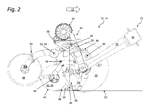
Fig. 2 shows an embodiment variant of a sowing coulter in a side view, with
metering
device, seed tube, catching element, and pressure roller.
Fig. 3 shows a detailed view of an embodiment variant of the unit including a
metering
device, seed tube, and catching element on a carrier.
Fig. 4 shows further embodiment variants of sowing coulters in different
possible
embodiments of carriers and their arrangement in five schematic side views
(Fig. 4a to Fig. 4e).
The same or equivalent elements of the invention are each designated by the
same
reference characters in the Figures 1 to 4e. Furthermore, and for the sake of
clarity, only the
reference characters relevant for describing the individual figures are
provided. It should be
understood that the detailed description and specific examples of the sowing
coulter according
to the invention, while indicating preferred embodiments, are intended for
purposes of
illustration only and are not intended to limit the scope of the invention.
Fig. 1 shows an embodiment variant of a sowing coulter arrangement 10
according to
the invention in a schematic perspective view, which sowing coulter
arrangement 10 can be
used, for example, with an agricultural machine for spreading agricultural
materials to be
distributed, such as seeds, fertilizer, or the like. Fig. 2 shows the
identical embodiment of the
sowing coulter arrangement 10 according to Fig. 1 in a side view. In each
case, the sowing
coulter arrangement 10 is represented opposite to the driving direction 12.
Such sowing coulter
arrangements 10 can be mounted, for example, at regular spacings to each other
on the frame
structure of an agricultural machine. The exemplary embodiment of the sowing
coulter
arrangement 10 according to Fig. 1 and 2 is a so-called single-disk coulter
14. The arrangement
according to the invention could, however, likewise be used for a double-disk
coulter or a tine
coulter or the like, with single-disk coulters, however, being preferentially
used.
I
CA 02996815 2018-02-27
- 10 -
The sowing coulter arrangement 10 is pivotably connected to a frame structure,
which
is not illustrated here, by way of a suspension device 16 or, as the case may
be, by way of a
rubber cord bearing as known from the prior art that is guided via a central
axis of rotation.
Other suspension devices 16 are, however, equally conceivable, such as flange
sheets or weld-
on plates or a parallelogram linkage (cf. Fig. 4) or the like. By means of the
suspension device
16, it is possible to radially swivel the entire sowing coulter arrangement 10
about the frame
structure and to thus move the sowing coulter arrangement 10, for example
between a lowered
position for driving in a field and a raised position for driving on the road.
Furthermore, a coulter
frame 20 is affixed to a bearing housing 18 of the suspension device 16 by
means of welding,
with other types of mounting being conceivable here as well. The appropriate
coulter
implements are mounted on the coulter frame 20. The coulter frame 20 is
disposed
asymmetrical to the bearing housing 18, but a symmetrical arrangement is also
possible. The
coulter frame is designed in multiple pieces and consists of a coulter tube
and mounting plates
affixed thereto. A one-piece design is equally conceivable.
A pivot-mounted coulter disk or cutting disk 22 is affixed to the coulter
frame 20. Said
coulter disk or cutting disk 22 is used to form a seed furrow in a ground
surface 23, where the
material to be distributed is subsequently placed. In order to ensure that the
seed furrow is
sufficiently large, the coulter disk 22 is preferably disposed at an angle
transverse to the driving
direction, with this angle being, for example, between approximately 4 and 8
. In the exemplary
embodiment, however, this angle is approximately 6 . Additionally, associated
with the coulter
disk 22 is a furrow opener 24 or, as the case may be, a so-called sowing skid
24, on the one
hand for preventing soil from adhering to the coulter disk 22, and on the
other hand for keeping
the seed furrow open until seed placement.
It is, however, also conceivable that in each case two oppositely positioned
coulter disks
,
22 are disposed on the coulter frame 20, thus forming a double-disk coulter.
By means of said
coulter disks 22 disposed at an angle in relation to each other, it is
likewise possible to create
a sufficiently large seed furrow. The wedge formed by the two coulter disks 22
is, for example,
at least 4 , preferably however, at least 8 or more.
A seed tube 26 is disposed laterally next to the at least one coulter disk 22
or, as the
case may be, behind the furrow opener 24 or between the two coulter disks 22.
The inlet 28 of
said seed tube 26 leads into a metering device 32, which is also located at
the sowing coulter
,
CA 02996815 2018-02-27
- 1 1 -
arrangement 10. The material to be distributed is at least to a large extent
separated or, as the
case may be, evenly dispersed by means of the metering device 32, for which
purpose various
principles of separation as known from the prior art can be applied. It is
possible to use such
metering devices as operate, for example, based on the principle of
differential pressure or
such as operate based on the principle of centrifugation. The metering device
32 according to
the exemplary embodiments of Figures 1 to 4 is a metering device 32 that
operates based on
the principle of centrifugation. For this purpose, a seed-air mixture is fed
to the metering device
32 via a spout 34. Located within the metering device 32 is a rotating
separating disk, which
has at least one pocket or opening at its outer circumference for the purpose
of receiving grains
of the material to be distributed. Grains are received from the pocket, they
are separated, and
they are conveyed to a dispensing area by a rotation of the separating disk
acting in connection
with a housing wall. The top end of the seed tube 26 ends in said dispensing
area. By way of
the rotation of the separating disk and by an airstream present in the
housing, the separated
material to be distributed undergoes an active acceleration, whereby the
grains are transported
through the seed tube 26 at a speed that is greater than the acceleration of
gravity. It would
also be possible, however, that the acceleration of the material to be
distributed is carried out
in a purely pneumatic manner. The material to be distributed could also be
transported through
the seed tube 26 without being accelerated.
In the exemplary embodiments of Figures 1 to 4, the seed tube 26 is in each
case
disposed perpendicular to the driving direction 12, and it bends into a curved
form 36 toward
the outlet 30 of the seed tube 26. Also conceivable, however, is a seed tube
26 that has varying
radiuses and shapes along its length. In particular, crescent-shaped or the
like seed tube
shapes are also conceivable.
Furthermore, the seed tube 26 is in each case mounted behind a furrow opener
24. It
is, however, also conceivable that the seed tube 26 ends in the furrow opener
24 or, as the
case may be, that it is guided through the furrow opener 24. It is likewise
conceivable for the
seed tube 26 to end in the furrow opener 24 and the furrow opener 24 to thus
form the
continuation of the seed tube 26. In particular, it is thus conceivable that
the seed tube 26 is
disposed between the at least one coulter disk 22 and the furrow opener 24. It
is moreover
conceivable that the furrow opener 24 is likewise disposed on the carrier 62.
It would thus be
conceivable for a unit composed of the metering device 32, the seed tube 26,
the catching
element 42, and the furrow opener 2, to be mounted to the sowing coulter
arrangement 10.
CA 02996815 2018-02-27
- 12 -
The outlet 30 of the seed tube 26 is inclined opposite to the driving
direction 14. This
results in a seed flow 38 that is, for example, at least largely tangential to
an outer contour or,
as the case may be, to a circumference 40, of a catching element 42 downstream
of the outlet
30 of the seed tube 26. After being dispensed from the seed tube 26, the
grains are slowed
down or, as the case may be, caught, by means of the catching element 42,
which is designed
as catching roller 44 in the exemplary embodiment. In this way, the
distributed material is
largely prevented from undesired rolling and undesired bouncing in the seed
furrow. The
catching element 42 can be depth-adjusted in relation to the coulter disk 22
or, as the case
may be, in relation to the carrier 62, by way of a connecting plate 46, for
example. The catching
element 42 is followed by a pressure roller 48 that is movably mounted via a
pivot point 50 and
that is preloaded by means of a spring 52. Via a latch 54, the preload force
of said spring 52
can be readjusted as well. The distributed material is pressed into the soil
by means of the
pressure roller 48, and the previously cut seed furrow is closed such that the
distributed material
is covered with soil.
The depth adjustment of the sowing coulter arrangement 10 is carried out by
means of
a depth control roller 56, which is mounted on the coulter frame 20 in a
rotatable manner as
well, and which is located on the opposite side of the coulter disk 22 or, as
the case may be, of
the furrow opener 24. For the purpose of depth adjustment, the height or, as
the case may be,
the position of the depth control roller 56 can be readjusted in relation to
the coulter disk 22 or,
as the case may be, in relation to the furrow opener 24, by means of an
adjustment lever 58
and gear teeth 60, whereby in turn the depth of the seed furrow can be
correspondingly
readjusted. The depth control roller 56 is moreover disposed in relation to
the coulter disk 22
such that, in addition to serving for depth control, the depth control roller
56 also serves as a
wiper for one side of the coulter disk 22.
As is clear from the Figures 1 and 2 and, in particular, from Fig. 3, the
metering device
32, the seed tube 26, and the catching element 42 are mounted as a unit on a
carrier 62. Said
carrier 62 is mounted on the coulter frame 20 in a rotatable manner via an
axle 64. Preferably,
said carrier 62 is preloaded in relation to a ground surface 23, for example
by means of a spring
or by means of a hydraulic cylinder or a pneumatic cylinder or the like. An
arrangement between
seed flow 38 or, as the case may be, an outlet 30 of the seed tube 26, in
relation to a
circumference 40 of the catching element 42 is at all times kept at least
largely constant,
independently of the sowing depth or, as the case may be, independently of the
working depth,
CA 02996815 2018-02-27
- 13 -
by means of the unit of seed tube 26 and catching element 42. This arrangement
is a tangential
arrangement in the Figures 2 and 3. Other arrangements are, however, also
conceivable.
If the seed tube 26 is part of the furrow opener 24, for example, then said
furrow opener
24 can also be mounted together with the seed tube 26, the catching element
42, and the
metering device 32 on the carrier 62.
In the exemplary embodiment, the carrier 62 is formed as a metal sheet, and
mounting
elements 66 for attaching the catching element 42 and the metering device 32
are associated
with it.
The carrier 62 in the exemplary embodiments of Figures 1 to 3 is in each case
connected to the coulter frame 20 in a rotatable manner via an axle 64.
Depending on the
particular working depth, such an arrangement results in different angles a
between a seed
flow 38 and a ground surface 23. It is also conceivable, however, that the
carrier 62 is
connected to the coulter frame 20 via a parallelogram linkage 68 or four-joint
arrangement, with
the result that an angle between a seed flow 38 and a ground surface 23 is at
all times largely
constant, independently of the working depth. This can be further improved by
connecting both
the carrier 62 and the suspension device 16 in each case by means of a
parallelogram linkage
68 to the coulter frame 20 or, as the case may be, to the frame structure.
Sowing coulter
arrangements 10 with such parallelogram linkages 68 are illustrated in the
Figures 4a to 4e.
Fig. 4a in this context shows a sowing coulter arrangement 10 with the
suspension
device 16 designed as parallelogram linkage 68. The parallelogram linkage 68
consists of an
upper link 70 and a lower link 72, which are each connected to a coulter frame
20 and to a
frame structure, which is not illustrated here, by means of coupling points
74. A coulter disk 22
and a pressure roller 48 are mounted on the coulter frame 20, as well as a
carrier 62 that is
pivotable via an axle 64, with in turn a metering device 32, a seed tube 26,
and a catching
element 42 being disposed on the carrier 62 such that they form a unit,
whereby the
arrangement of an outlet 30 of the seed tube 26 in relation to the catching
element 42 is at all
times kept largely constant.
Furthermore, Fig. 4b shows a sowing coulter arrangement 10 that is mounted in
a
pivotable manner via a swivel axle 76 and by means of a coulter frame 20 on a
frame structure,
which is not illustrated here. A coulter disk 22 and a pressure roller 48 are
mounted on the
CA 02996815 2018-02-27
- 14 -
coulter frame 20, as well as a carrier 62 that is pivotable via a
parallelogram linkage 68, with in
turn a metering device 32, a seed tube 26, and a catching element 42 being
disposed on the
carrier 62 such that they form a unit, whereby the arrangement of an outlet 30
of the seed tube
26 in relation to the catching element 42 is at all times kept largely
constant. The parallelogram
linkage 68 consists of an upper link 70 and a lower link 72, which each
establishes a pivotable
connection between the carrier 62 and the coulter frame 20 via coupling points
74.
Beyond that, Fig. 4c shows a combination of embodiment variants of the sowing
coulter
arrangement 10 according to the Figures 4a and 4b. In this instance, the
suspension device 16
of the sowing coulter arrangement 10 is designed as a parallelogram linkage
68, and it consists
of an upper link 70 and a lower link 72, which are each connected to a coulter
frame 20 and to
a frame structure, which is not illustrated here, by means of coupling points
74. A coulter disk
22 and a pressure roller 48 are mounted on the coulter frame 20, as well as a
carrier 62 that is
pivotable via a further parallelogram linkage 68, with in turn a metering
device 32, a seed tube
26, and a catching element 42 being disposed on the carrier 62 such that they
form a unit,
whereby the arrangement of an outlet 30 of the seed tube 26 in relation to the
catching element
42 is at all times kept largely constant. The parallelogram linkage 68
consists of an upper link
70 and a lower link 72, which each establishes a connection between the
carrier 62 and the
coulter frame 20 via coupling points 74.
Furthermore, Fig. 4d shows a sowing coulter arrangement 10 that is mounted in
a
pivotable manner via a swivel axle 76 and by means of a coulter frame 20 on a
frame structure,
which is not illustrated here. A coulter disk 22 and a pressure roller 48 are
mounted on the
coulter frame 20. A carrier 62 is mounted in a pivotable manner via a
parallelogram linkage 68
on a frame structure of an agricultural machine, which are not illustrated
here, with in turn a
metering device 32, a seed tube 26, and a catching element 42 being disposed
on the carrier
62 such that they form a unit, whereby the arrangement of an outlet 30 of the
seed tube 26 in
relation to the catching element 42 is at all times kept largely constant. The
parallelogram
linkage 68 consists of an upper link 70 and a lower link 72, which each
establishes a pivotable
connection between the carrier 62 and the frame structure via coupling points
74.
A further embodiment variant is illustrated in Fig. 4e. The suspension device
16 of the
sowing coulter arrangement 10 together with the carrier 62 forms a
parallelogram linkage 68.
Said parallelogram linkage 68 consists of an upper link 70 and a lower link
72, which are each
CA 02996815 2018-02-27
- 15 -
connected to a frame structure via swivel axles 76. The upper link 70 has a
coupling point 74,
via which the carrier 62 is guided. The coulter frame 20 has a further
coupling point 74, via
which the carrier 62 is also guided, whereby in turn a parallelogram linkage
68 is formed. That
is to say that the sowing coulter arrangement 10 is, on the one hand,
connected to the frame
structure via a central swivel axle 76. On the other hand, the carrier 62,
that is to say the unit
of metering device 32, seed tube 26, and catching element 42, is guided via a
parallelogram
linkage 68, with the result that a depth adjustment of the sowing coulter
arrangement 10 has
no influence on an angle position of the seed flow in relation to the ground
surface. This
arrangement, too, is at all times kept largely constant. A coulter disk 22 for
creating a seed
furrow and a pressure roller 48 for closing the seed furrow are furthermore
mounted on the
coulter frame 20.
In general, the "sowing coulter arrangement" 10 according to the invention is
referred
to in the context of the above description of the figures. In some places, the
arrangement 10
according to the invention is also referred to "seed drill coulter" or as
"sowing coulter" for short.
It should be noted here that these terms are generally intended as synonyms
and they can be
optionally substituted for each other.
The invention has been described with reference to a preferred embodiment.
Those
skilled in the art will appreciate that numerous changes and modifications can
be made to the
preferred embodiments of the invention and that such changes and modifications
can be made
without departing from the spirit of the invention. It is therefore intended
that the appended
claims cover all such equivalent variations as fall within the true spirit and
scope of the
invention.
CA 02996815 2018-02-27
- 16 -
List of Reference Characters
Sowing coulter arrangement, seed drill coulter arrangement
12 Driving direction
14 Single-disk coulter
16 Suspension device
18 Bearing housing
Coulter frame
22 Coulter disk, cutting disk
23 Ground surface
24 Furrow opener
26 Seed tube
28 Inlet
Outlet
32 Metering device
34 Spout
36 Curved form
38 Seed flow
Circumference
42 Catching element
44 Catching roller
46 Connecting plate
48 Pressure roller
Pivot point
52 Spring,
54 Latch
56 Depth control roller
58 Adjustment lever
Gear teeth
62 Carrier
64 Axle
66 Mounting elements
68 Parallelogram linkage
Upper link
72 Lower link
74 Coupling points
76 Swivel axle