Sélection de la langue

Search

Sommaire du brevet 2998033 

Énoncé de désistement de responsabilité concernant l'information provenant de tiers

Une partie des informations de ce site Web a été fournie par des sources externes. Le gouvernement du Canada n'assume aucune responsabilité concernant la précision, l'actualité ou la fiabilité des informations fournies par les sources externes. Les utilisateurs qui désirent employer cette information devraient consulter directement la source des informations. Le contenu fourni par les sources externes n'est pas assujetti aux exigences sur les langues officielles, la protection des renseignements personnels et l'accessibilité.

Disponibilité de l'Abrégé et des Revendications

L'apparition de différences dans le texte et l'image des Revendications et de l'Abrégé dépend du moment auquel le document est publié. Les textes des Revendications et de l'Abrégé sont affichés :

  • lorsque la demande peut être examinée par le public;
  • lorsque le brevet est émis (délivrance).
(12) Demande de brevet: (11) CA 2998033
(54) Titre français: DISPOSITIF DE RECOLTE DE PRODUITS A TIGE SUR PIED
(54) Titre anglais: DEVICE FOR HARVESTING OF STALK MATERIAL
Statut: Réputée abandonnée et au-delà du délai pour le rétablissement - en attente de la réponse à l’avis de communication rejetée
Données bibliographiques
(51) Classification internationale des brevets (CIB):
  • A01D 45/02 (2006.01)
  • A01D 34/835 (2006.01)
(72) Inventeurs :
  • BAYE, DIETRICH (Allemagne)
  • HANSKOTTER, WERNER (Allemagne)
  • TIESSEN, REIMER (Allemagne)
  • HEMMESMANN, ANDRE (Allemagne)
(73) Titulaires :
  • CARL GERINGHOFF GMBH & CO. KG
(71) Demandeurs :
  • CARL GERINGHOFF GMBH & CO. KG (Allemagne)
(74) Agent: MARKS & CLERK
(74) Co-agent:
(45) Délivré:
(86) Date de dépôt PCT: 2016-09-07
(87) Mise à la disponibilité du public: 2017-03-16
Licence disponible: S.O.
Cédé au domaine public: S.O.
(25) Langue des documents déposés: Anglais

Traité de coopération en matière de brevets (PCT): Oui
(86) Numéro de la demande PCT: PCT/EP2016/001507
(87) Numéro de publication internationale PCT: EP2016001507
(85) Entrée nationale: 2018-03-08

(30) Données de priorité de la demande:
Numéro de la demande Pays / territoire Date
10 2015 115 100.6 (Allemagne) 2015-09-08

Abrégés

Abrégé français

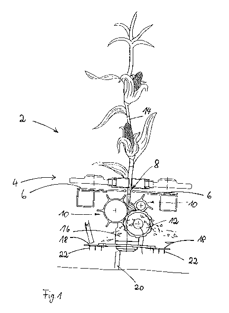
L'invention concerne un dispositif (2) de récolte de produits à tige sur pied, comportant une zone d'introduction, un dispositif de transport (4), un dispositif de cueillage et un dispositif de coupe des tiges agencé dans un plan situé au-dessous du dispositif de cueillage et présentant au moins un couteau tournant dans un plan horizontal ou au moins à peu près horizontal. L'invention vise à créer un dispositif qui permette que les morceaux de chaume, en plus de la coupe, soient également détériorés quant à leur structure végétale de telle manière que les bactéries et l'humidité puissent pénétrer plus facilement à l'intérieur d'un morceau de tige, en particulier dans un chaume restant sur le champ. À cet effet, au moins un élément de percussion (22) qui s'élève au-delà de l'épaisseur de la lame du couteau est réalisé au niveau du couteau tournant (18).


Abrégé anglais

The invention relates to a device (2) for harvesting stalk material, comprising a feed region, a conveyor device (4), a picking device, and a device which is arranged on a plane below the picking device for cutting stalks and has at least one cutter that rotates in a circulating manner on a horizontal or at least approximately horizontal plane. The aim of the invention is to provide a device with which the vegetable structure of the stubble pieces are damaged in addition to being cut such that bacteria and moisture can more easily penetrate the interior of a stalk piece, in particular stubble standing on the field. This is achieved in that at least one impact element (22) is formed on the cutter (18) which rotates in a circulating manner, said impact element rising over the thickness of the cutter blade.

Revendications

Note : Les revendications sont présentées dans la langue officielle dans laquelle elles ont été soumises.


Claims
1. A device (2) for harvesting of stalk material, with a feed area, a
conveyor device (4), a picking device and a device arranged in a plane below
the picking device for cutting of stalks, which has a circulating rotating
blade
in a horizontal plane or at least an approximately horizontal plane,
characterized in that on the circulating rotating cutter (18) at least one
impact element (22) is configured, which extends beyond the thickness of the
cutter blade plate.
2. The device (2) of claim 1, characterized in that the cutter (18) is
driven
at an r.p.m. of at least 1500.
3. The device (2) of claim 1 or 2, characterized in that the impact element
(22) has a cylindrical shape with a rounded tip.
4. The device (2) of one of the foregoing claims, characterized in that the
impact element (22) is configured as a solid, made from a metallic material,
the outer layer of which additionally is hardened.
5. The device (2) of one of the foregoing claims, characterized in that the
impact elements (22) are arranged only on the cutter side facing the ground.
6. The device (2) of one of the foregoing claims, characterized in that the
at least one impact element (22) is arranged in the middle area of the cutter
width.
7. The device (2) of one of the foregoing claims, characterized in that the
at least one impact element (22) is screwed into the cutter (18) with a
countersunk screw.
8. The device (2) of one of the foregoing claims, characterized in that
beneath the picking plates (6) at least two picking rollers (10) are arranged
8

along the picking gap (8), the minimum circumscribed circles of which
overlap at least in some areas.
9. The device (2) of
claim 8, characterized in that at intervals along the
length of the picking gap (8), fixed or rotating blades (12) are arranged that
extend into the minimum circumscribed circles of the picking rollers (10).
9

Description

Note : Les descriptions sont présentées dans la langue officielle dans laquelle elles ont été soumises.


CA 02998033 2018-03-08
Device for Harvesting of Stalk Material
The present invention relates to a device for harvesting of stalk material,
with
a feed area, a conveyor device, a picking device and a device situated in a
plane below the picking device for cutting of stalks, which has at least one
rotating circulating cutter in a horizontal, or at least approximately
horizontal,
plane.
A generic device is known from the publication DE 203 03 819 U1. After a
stalk of the stalk material, such as that of a corn plant, has, in this
device,
entered into the harvester, been pulled downwards by picking rollers and the
targeted harvest material, such as ears from the corn plant, have been
separated by the picking device from the cornstalk by picker plates, the
remaining cornstalk is conveyed on downwards. A stalk pulled downward
can be cut by fixed or rotating cutters, which are arranged in the area of the
picking rollers. However, the stalk is cut off from the root system remaining
in
the ground, close to the ground, by a separate cutter device with at least one
cutter that circulates in rotating fashion in a horizontal plane. The
circulating
cutter can additionally cut stalk pieces conveyed downwards by the picking
rollers into shorter stallk pieces, which then are ejected onto the field.
There
the stalk pieces can decay. The ears of corn separated from the stalk are
brought by the conveyor device to a threshing machine.
Since the cut surfaces of the stalk pieces are smoothly cut by the chaff
cutter
rotating in the horizontal plane, some time must pass until moisture and
bacteria penetrate from without into the interior of a stalk piece and
accelerate the decay process. This holds up the rotting process. This
especially holds true for the stubble, which remains erect on the field. Often
the still standing stubble is occupied by corn borers, whose caterpillars
later
cause considerable damage in corn stocks. To prevent this, the stubble
needs to be more severely damaged.
REPLACEMENT PAGE (RULE 26)
1

CA 02998033 2018-03-08
Accordingly, it is the object of the present invention to create a device by
which the stubble pieces, in addition to being cut, are so additionally
damaged in their plant structure that bacteria and moisture can penetrate
more easily into the interior of a stalk piece, especially into stubble
standing
in the field.
The object is attained for a generic device in that on the cutter rotating in
circulating fashion, at least one impact element is configured which projects
over the thickness of the cutter blade plate.
The cutter blade plate is the part of the cutter that carries the cutter
blade.
The cutter blade has a sharpened cutting edge that cuts through a plant at
the interface in a section. The cutter blade plate per se is normally
configured
to be flat, in order that the blade can get through the cut material with as
little
force as possible. Acc:ording to the invention, the blade additionally has one
or more impact elements, which project over the thickness of the cutter blade
plate and, when the blade rotates and a stalk is cut, hit the stubble body.
Upon impact, the outer layers of the stem axis are torn off, the attachment
tissue of the stalk found beneath is defibered and spliced along the
longitudinal axis of the stubble. By this means, considerable damage is
inflicted on the stubble hit by the impact element. The smooth surface is
destroyed. The surface is considerably enlarged by the destruction, through
which bacteria and moisture can more easily penetrate into the stubble. The
stubble decays more quickly thereby. The destructive effect on the stubble
can be increased if multiple impact elements are configured on one blade.
The energy which needs to be expended to get the blade to rotate with the
impact element or elements is increased by the impact elements in
comparison to a traditional cutter. Since an impact element or elements can
only be attached at separate places on a cutter, the additional energy
expended does remain comparatively small. This especially holds true if the
contour of the blade, apart from the impact element or elements, remains
unchanged and favorable in energy terms.
REPLACEMENT PAGE (RULE 26)
2

CA 02998033 2018-03-08
The degree of destruction to the stubble attainable by the impact elements is
so great, that depending on the harvested material, subsequent mulching
can be dispensed with.
It is also advantageous that the stubble destruction be possible before
stubble is rolled upon by the wheels of a harvester, and undamaged stubble
is compressed into the ground. Such stubble would not be reachable for
subsequent stubble treatment and could likely damage subsequent growth
through insect infestation and fusarium fungi.
According to one embodiment of the invention, the cutter is driven at an
r.p.m. of at least 1,500. With such an r.p.m of a rotating blade in a picker
attachment, the result would be the impact element hitting the stubble at a
very high impact speed. The energy acting on the stubble acts beyond the
direct zone of contact of the impact element with the stubble and also
damages neighboring stubble areas that the impact element itself does not
directly reach. Due to this distant action of the impact element, the
harvester
no longer needs to be run so close to the ground that the stubble is cut to a
length of 5 cm that is viewed as critical for corn borers. The harvester can
rather run at a greater distance over the ground, through which damage by
contact with foreign objects is reduced. At such a cutter r.p.m., an
individual
stalk of stubble is also impacted multiple times by an impact element, which
additionally increased its degree of destruction.
According to one embodiment of the invention, the impact element has a
cylindrical shape with a rounded tip. The cylindrical shape is ideal to absorb
the impact energy into the material of the impact element and to distribute
it,
without the impact element itself being deformed or destroyed. Material
ablation caused by usage on the side of the impact element pointing in the
rotational direction is evenly distributed over the surface, so that the
impact
element has a long service life. The same holds true for the rounded form of
the impact element tip.
REPLACEMENT PAGE (RULE 26)
3

CA 02998033 2018-03-08
According to one embodiment of the invention, the impact element is
produced to be solid, made of a metallic material, with its outer layer
additionally hardened. A metallic material such as steel has a high resistance
capacity, resulting in long service life for the impact element. The service
life
is additionally increased by being produced as a solid. The hardening of the
outer layer reduces material ablation through constant contact with the
stubble.
According to one embodiment of the invention, the impact elements are
situated only on the cutter side facing the ground. Since especially the
stubble is to be damaged, with an arrangement of impact elements only on
the side of the blade facing the ground, additional energy expenditure
remains limited.
According to one embodiment of the invention, at least one impact element is
situated in the center area of the blade width. This arrangement is
advantageous, because in this area, the blade has its greatest strength.
According to one embodiment of the invention, the at least one impact
element is screwed into the blade with a countersunk screw. The
countersunk screw can be countersunk in the material of the blade, so that it
does not project over the profile of the blade and can be abraded by material
contact. The screw remains capable of functioning. If the first side of the
blade should be worn, without large expense the impact element can be
screwed onto the other side of the blade, so that even with a reversed blade
when the blade rotational direction is not changed it is arranged with the
second blade side in the turning direction on the underside of the blade.
According to one embodiment of the invention, beneath the picking plates at
least two picking rollers are arranged along the picking gap, the minimum
circumscribed circles of which overlap at least in some areas. In combination
with the previously described impact elements, through the use of at least
two picking rotors beneath the picking plates, there results a very efficient
comminution system, which securely grips the cornstalks, conveys them
REPLACEMENT PAGE (RULE 26)
4

CA 02998033 2018-03-08
downward, and not only comminutes and defibers the cut-off stalk parts, but
also the upper ends of the stubble still standing in the field.
According to one embodiment of the invention, at intervals along the length
of the picking gap, fixed or rotating blades are arranged, projecting into the
minimum circumscribed circles of the picking rollers. The fixed or rotating
blades cause a very effective comminution of the plant residues, which are
drawn downward through the picking gap. By the use of fixed or rotating
blades, which extend into the minimum circumscribed circles of the picking
rotors, rapid forward speeds can be achieved during the harvest, without
having to accept comminution performance that remains at the same good
level, and simultaneous damage and defibering of the stubble ends standing
on the ground.
Express attention is drawn to the fact that the previously explained
embodiments of the invention can be per se, or also combined in any
combination with each other with the subject of the main claim.
Further variations and configurations of the invention can be gleaned from
the following subject-matter specification and the drawings.
The invention will now be explained in greater detail using the embodiment
example. Shown are:
Figure 1: a sectional view of a part of the harvester.
Figure 2: a view of the assembly shown in figure 1 from in front
Figure 3: a view of the underside of the assembly shown in figure 2 with
the impact elements on the blades.
Figure 1 shows a section of a device 2 for harvesting of stalk material. The
device has available conveyor device 4, which in the embodiment consists of
two opposite-placed conveyor chains, which on their outer side have a
REPLACEMENT PAGE (RULE 26)

CA 02998033 2018-03-08
number of followers, by which ears of corn can be conveyed away from the
cornstalk 14.
The ears of corn are separated from cornstalk 14 by a picking device which
in the embodiment consists of two picking plates 6, which with their sides
facing each other delimit a picking gap 8. Cornstalk 14 glides through the
length of picking gap 8, while the picking rollers 10 situated below picking
gap 8 grasp cornstalk 14 and pull it downwards. In the embodiment shown in
figure 1, additionally one more blade 12 acts together with picking rollers 10
to comminute cornstalk 14 grasped by picking rollers 10.
Down into the area below picking rollers 10 extends a rotor shaft 16, on the
lower end of which in the embodiment example two cutters 18 are attached.
The two blades 18 rotate in a horizontal plane. With a rotary motion of the
cutters 18, these separate the cornstalk from the stubble 20 remaining in the
ground. The cutters 18 can with a rotational motion in addition also encounter
parts of the cornstalk which fall down from picking rollers 10 and cutter
blade
12.
In the embodiment example, the two cutters 18 are equipped with three
additional impact elements 22. Impact elements 22 are on the underside of
cutters 22 facing the ground. Impact elements 22 project over the cross-
sectional surface of the two cutters 18, Thus they extend closer to the ground
than the blades of the two cutters 18.
In figure 1, stubble 20 is shown in its still intact form. When stubble 20 has
in
fact had multiple encounters with impact elements 22, stubble 20 in its upper
area has lost its cylindrical shape. It then is severely damaged and spliced.
Figure 2 is a view of the assembly shown in figure 1, seen from the front. As
can be gleaned from figure 2, impact element 22 has a cylindrical shape with
a rounded tip 24. Impact element 22 consists of a metallic material and is
designed to be solid.
REPLACEMENT PAGE (RULE 26)
6

CA 02998033 2018-03-08
From the enlarged view from below in figure 3 of the assembly shown in
figure 2, it is perceived that the impact elements 22 are arranged in the
center area of the width of cutter 26.
The embodiment example described above serves only for explanation of the
invention. The invention is not limited to the embodiment example shown. It
will pose no difficulties for one skilled in the art to alter the embodiment
example in a way he finds suitable, to adapt it to a specific application.
REPLACEMENT PAGE (RULE 26)
7

Dessin représentatif
Une figure unique qui représente un dessin illustrant l'invention.
États administratifs

2024-08-01 : Dans le cadre de la transition vers les Brevets de nouvelle génération (BNG), la base de données sur les brevets canadiens (BDBC) contient désormais un Historique d'événement plus détaillé, qui reproduit le Journal des événements de notre nouvelle solution interne.

Veuillez noter que les événements débutant par « Inactive : » se réfèrent à des événements qui ne sont plus utilisés dans notre nouvelle solution interne.

Pour une meilleure compréhension de l'état de la demande ou brevet qui figure sur cette page, la rubrique Mise en garde , et les descriptions de Brevet , Historique d'événement , Taxes périodiques et Historique des paiements devraient être consultées.

Historique d'événement

Description Date
Demande non rétablie avant l'échéance 2022-03-08
Le délai pour l'annulation est expiré 2022-03-08
Réputée abandonnée - omission de répondre à un avis relatif à une requête d'examen 2021-11-29
Lettre envoyée 2021-09-07
Réputée abandonnée - omission de répondre à un avis sur les taxes pour le maintien en état 2021-03-08
Représentant commun nommé 2020-11-07
Lettre envoyée 2020-09-08
Représentant commun nommé 2019-10-30
Requête pour le changement d'adresse ou de mode de correspondance reçue 2019-07-24
Inactive : Réponse à l'art.37 Règles - PCT 2018-06-20
Inactive : Page couverture publiée 2018-04-18
Inactive : CIB en 1re position 2018-03-26
Inactive : Notice - Entrée phase nat. - Pas de RE 2018-03-26
Inactive : CIB attribuée 2018-03-22
Inactive : Demande sous art.37 Règles - PCT 2018-03-22
Inactive : CIB attribuée 2018-03-22
Demande reçue - PCT 2018-03-22
Exigences pour l'entrée dans la phase nationale - jugée conforme 2018-03-08
Demande publiée (accessible au public) 2017-03-16

Historique d'abandonnement

Date d'abandonnement Raison Date de rétablissement
2021-11-29
2021-03-08

Taxes périodiques

Le dernier paiement a été reçu le 2019-07-12

Avis : Si le paiement en totalité n'a pas été reçu au plus tard à la date indiquée, une taxe supplémentaire peut être imposée, soit une des taxes suivantes :

  • taxe de rétablissement ;
  • taxe pour paiement en souffrance ; ou
  • taxe additionnelle pour le renversement d'une péremption réputée.

Les taxes sur les brevets sont ajustées au 1er janvier de chaque année. Les montants ci-dessus sont les montants actuels s'ils sont reçus au plus tard le 31 décembre de l'année en cours.
Veuillez vous référer à la page web des taxes sur les brevets de l'OPIC pour voir tous les montants actuels des taxes.

Historique des taxes

Type de taxes Anniversaire Échéance Date payée
TM (demande, 2e anniv.) - générale 02 2018-09-07 2018-03-08
Taxe nationale de base - générale 2018-03-08
TM (demande, 3e anniv.) - générale 03 2019-09-09 2019-07-12
Titulaires au dossier

Les titulaires actuels et antérieures au dossier sont affichés en ordre alphabétique.

Titulaires actuels au dossier
CARL GERINGHOFF GMBH & CO. KG
Titulaires antérieures au dossier
ANDRE HEMMESMANN
DIETRICH BAYE
REIMER TIESSEN
WERNER HANSKOTTER
Les propriétaires antérieurs qui ne figurent pas dans la liste des « Propriétaires au dossier » apparaîtront dans d'autres documents au dossier.
Documents

Pour visionner les fichiers sélectionnés, entrer le code reCAPTCHA :


Pour visualiser une image, cliquer sur un lien dans la colonne description du document. Pour télécharger l'image (les images), cliquer l'une ou plusieurs cases à cocher dans la première colonne et ensuite cliquer sur le bouton "Télécharger sélection en format PDF (archive Zip)" ou le bouton "Télécharger sélection (en un fichier PDF fusionné)".

Liste des documents de brevet publiés et non publiés sur la BDBC .

Si vous avez des difficultés à accéder au contenu, veuillez communiquer avec le Centre de services à la clientèle au 1-866-997-1936, ou envoyer un courriel au Centre de service à la clientèle de l'OPIC.


Description du
Document 
Date
(aaaa-mm-jj) 
Nombre de pages   Taille de l'image (Ko) 
Description 2018-03-07 7 263
Abrégé 2018-03-07 1 44
Dessins 2018-03-07 3 123
Revendications 2018-03-07 2 41
Dessin représentatif 2018-03-07 1 18
Avis d'entree dans la phase nationale 2018-03-25 1 195
Avis du commissaire - non-paiement de la taxe de maintien en état pour une demande de brevet 2020-10-19 1 539
Courtoisie - Lettre d'abandon (taxe de maintien en état) 2021-03-28 1 552
Avis du commissaire - Requête d'examen non faite 2021-09-27 1 532
Avis du commissaire - non-paiement de la taxe de maintien en état pour une demande de brevet 2021-10-18 1 553
Courtoisie - Lettre d'abandon (requête d'examen) 2021-12-28 1 551
Modification - Description 2018-03-07 9 343
Modification - Dessins 2018-03-07 3 85
Modification - Abrégé 2018-03-07 2 95
Rapport de recherche internationale 2018-03-07 2 58
Modification - Revendication 2018-03-07 2 55
Demande d'entrée en phase nationale 2018-03-07 3 118
Requête sous l'article 37 2018-03-21 1 55
Réponse à l'article 37 2018-06-19 1 26