Note : Les descriptions sont présentées dans la langue officielle dans laquelle elles ont été soumises.
1/12
CENTERLINE AND ANGLE FINDER LAYOUT TOOL FOR CYLINDRICAL AND
= RADIAL SURFACES
Priority Claim
[0001] This application claims priority to U.S. Provisional Patent App. No.
62/472,677,
filed on March 17, 2017, the contents of which are herein incorporated by
reference.
Field of the Invention
[0002] The current invention is generally directed to an improved type of
portable
geometrical instrument for angular measurements. In particular, it is a hand
tool or
instrument apparatus and method for the purpose of producing, for example,
accurately-
placed indication marks, reference points, center-punch marks, and drilled
holes or pilot
holes as may be preferred, into or upon generally cylindrical surfaces at
predetermined
orientations or desired angels with respect to an imaginary, generally
vertical or horizontal
reference plane, as defined by a central axis and the directional force of
gravity. Practical
applications for this invention are directed toward various cylindrical or
radial surfaces in a
variety of applications. Such surfaces may include, for example, metal or
plastic plumbing
and piping, structural and mechanical round tubing, round tubular electrical
conduit, circular
ductwork, machinist operations, round woodwork, or otherwise practically any
rounded object
including a surface defined as having a generally constant radius from a
single imaginary
reference line or central axis. Preferably and ideally, a point coincident
with an imaginary
central axis at the outer cylindrical or radial surface will be permanently
marked, and will at
least be temporarily indicated when the geometrical instrument is properly
used. It is
preferable that the central line of the axis of the cylinder or radial surface
is as close to
horizontal as possible when angle reference measurements or reference points
are being
taken or established. However, this preference is not critical to the intent
and effective use of
the invention. This inherent aspect of the current invention is of
significance due to the fact
that the force of gravity itself is employed as a primary reference for the
geometrical
instrument's measurements and indicating capabilities. The accuracy of the
improved
CA 2998237 2018-03-15
2/12
angular measurement tool or geometrical instrument apparatus tends to
significantly and
progressively improve as its own ideal vertical axis of operation becomes more
closely
aligned with the true vertical force of gravity.
[0003] The essential and primary scope and purpose of the current invention
represents a
simple and improved hand layout tool, apparatus, and method directed toward
skilled and
industrial trades, or for use within other similar mechanical layout and user
applications. The
current invention allows the trades technician or user to quickly and
accurately determine or
otherwise identify the outer or inner centerline of a radial or cylindrical
surface feature at a
selected or desired angle. Alternately, the current invention can allow the
user to quickly,
easily, and accurately measure or otherwise determine the included angle
between two
imaginary planes, with a first plane defined as being coincident with the
central axis of the
cylindrical or radial surface and a first out on an outer or inner cylindrical
or radial surface,
and a second plane defined as being coincident with the central axis of the
cylindrical or
radial surface and a second pout on an outer or inner cylindrical or radial
surface. For
example, the included angel or difference between these two imaginary plane-
angle
measurements may be the desired resulting angle of interest to the user or
technician.
Additionally, the ease and speed at which the invention may be adjusted to
either interior or
external cylindrical or radial surfaces as desired, and the speed at which
relative angle
measurements may be applied and otherwise indicated with respect to inner or
outer
cylindrical or radial surfaces represents at least one of the key and primary
advantages of the
current invention.
Backoround of the Invention
[0004]
The application and use of the current invention generally relates to skilled
trades,
machinists, plumbing and piping, woodworking, general industry, and user in
particular
specific applications where it becomes necessary to accurately measure,
layout, locate, and
other indicate, mark, center-punch, or drill a point at the center of an inner
or outer cylindrical
shape at a desired angle for any number or variety of reasons. Apart from the
current
invention, the exact ways and means to accomplish the desired results may vary
widely and
depend entirely upon the particular common tools that may be readily
available, as well as
the particular skill, experience, and ingenuity of the particular user or work
group, as well as
CA 2998237 2018-03-15
3/12
the levels of experience, knowledge, know-how, and established types of
processes
involved.
[0005] Conventional hand measurement tools may be typically employed for such
tasks
and used in various ways or combinations, ultimately producing an uncertain
range of
difficulty and potential outcomes leading to various degrees of failure or
success through
inconsistent means and methods. Conventional hand tools, for example, may
include, but
not be limited to: marking pencils and pens, flexible measuring tapes,
protractors, spirit
levels, straight-edges, rulers, squares, string and chalk-lines, plumb-bobs,
dividing
compasses, scribes, punches, hammers, drills, various types of paper,
cardboard, and
adhesive tapes. As already state, the various ways and means that such common
tools,
materials, and know-how can be incorporated and employed can vary
dramatically,
producing equally mixed expectations and results. It is the object of this
invention to provide
a solution to this problem by providing a unique and specialized, yet
versatile, hand tool and
measurement apparatus that simplifies the processes of determining or laying
out a particular
point or position at a specific angle on a cylindrical or radial surface.
Further, it is the object
of this invention to provide an accurate, concise, simplified, and consistent
means and
method for determining, defining, and measuring a specific point or position
at a specific
angle on a cylindrical or radial surface of interest. The current invention
provides a
significant level of simplicity, advantages, and benefits beyond that of
existing tools and
methods currently known to the various skilled trades and industries.
Summary of the Invention
[0006] The current geometrical instrument, apparatus, and method offers to
provide a
number of improvements, advantages, and benefits over that of existing methods
and known
processes involving a variety, and combinations of, common measurement
instruments and
hand tools.
Brief Description of the Drawings
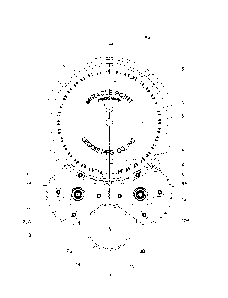
[0007] FIG. 1A illustrates a front or plan view of the current invention,
including hidden
lines, where the improved geometrical instrument or center-finder measurement
tool is
engaged for generally two-point contact at the outer surface of a cylindrical
object at the
CA 2998237 2018-03-15
4/12
respective flat surfaces of two rotatably operated and intermeshed gear
wheels, and where
the instrument is being held (operator's hands not shown) at a desired
vertical position, as
indicated by the needle on the dial of the instrument indicating zero degrees
with respect to
the vertical in the downward direction.
[0008] FIG. 1B illustrates a front or plan view of the current invention,
including fewer
hidden lines, where the improved geometrical instrument or center-finder
measurement tool
is engaged for generally two-point contact at the outer surface of a
cylindrical object at the
respective flat surfaces of two rotatably operated and intermeshed gear
wheels, and where
the instrument is being held (operator's hands not shown) at a desired
vertical position, as
indicated by the needle on the dial of the instrument indicating zero degrees
with respect to
the vertical in the downward direction.
[0009] FIGS. 2A and 2B illustrate perspective views of a first embodiment of
the current
invention where the center-finder invention apparatus is engaged with a round
object (e.g., a
metal pipe or tube), for example, and where the center axis of the tube is
generally
horizontal. As shown previously in FIG. 1, the respective and opposing flat
faces of the two
rotatably intermeshed gear wheels are held in firma and simultaneous contact
(operator's
hands not shown) with the surface of the cylindrical object. A pointed and
hardened steel
punch slidably engaged through a close-fitting central hole through the body
of the
instrument can then be struck at the uppermost head end with a hammer, thus
providing a
small indentation or indication mark on the surface of the cylindrical object
or tube at the
desired angle as indicated by the needle and marked graduations on the face of
the dial of
the instrument.
[0010] FIGS. 3A and 3B illustrates perspective views of a second embodiment of
the
current invention, where the center-finder invention apparatus is engaged with
a round object
(e.g. a metal tube or pipe), for example, and where the center axis of the
tube is generally
horizontal. As shown previously in FIGS. 1 and 2, the respective and opposing
flat faces of
the two rotatably intermeshed gear wheels are held in firm and simultaneous
contact
(operator's hands not shown) with the surface of the cylindrical object. In
this second
embodiment, a long and close-fitting metal twist drill is inserted for free
rotating contact
through the body of the instrument. In this example, a cordless electric drill
is used to spin
and drive the metal twist drill into the surface and/or through the
cylindrical object, as desired.
CA 2998237 2018-03-15
5/12
The precise angle of the hole to be produced is provided by means of holding
the instrument
apparatus at the desired angle, as indicated by the needle and marked
graduations on the
face of the dial of the instrument.
Detailed Description
[0011] The purpose and function of the current geometrical instrument tool
invention and
apparatus and method is to produce indication marks, punch marks, or drilled
holes and pilot
holes at a desired angle upon or through a cylindrical or radial surface.
[0012] As shown in FIGS. 1A and 1B, the current geometrical instrument tool 1
is
comprised of a structural frame plate 2, which provides primary structural
support and
mechanical location for the remaining associated components of the device. A
mechanical
dial indicating protractor 3 (currently available from Cullen-Legois
Manufacturing, Inc., 2850
Wisconsin Street, Sturtevant, WI 53177) is securely mounted and affixed to
structural frame
plate 2. While the essential function of the mechanical dial indicating
protractor 3 is to
determine precise angels with respect to gravity, the internal construction,
operation, and
mechanics of the mechanical dial indicating protractor 3 itself may be
generally disclosed in
greater detail through published manufacturer information and through U.S.
Pat. No. 2,822m
623 to R.J. Legois, titled Marking Gauge Having Means for Securing Said Gauge
to
Workpieces, issued February 11, 1958, the contents of which are hereby
incorporated by
reference. As such, the dial indicating protractor 3 will not be described in
greater detail
within this disclosure.
[0013] The items of particular interest for this particular component are
the indicating
needle 4 and the graduated face of the dial 5, calibrated to 360 degrees and
marked in
quadrants of 0 to 90 degree graduations, respectively, at its outer periphery.
Additionally, a
center position indicating through-hole 6 (shown in FIG. 1A) is disposed
through the body of
the indicating protractor 3, and is oriented and calibrated for precise
alignment coincident
with respect to an imaginary central axis 15 of a cylindrical object 14 and
with respect to the
remaining geometry and dimensional characteristics of the tool 1. At the lower
portion of the
structural frame plate 2 are opposing left sets 7,9, and right sets 8,10, of
gear-wheels,
respectively, which are pivotably attached to the structural frame plate 2 for
rotation about an
axis of generally free rotation at pivot bolts 11, 12, respectively. See also
FIGS. 2A and 2B.
CA 2998237 2018-03-15
6/12
[0014] Gear teeth 7A of left gear-wheel 7 and gear teeth 8A of right gear-
wheel 8 are
intermeshed for engagement such that the respective flat contact portions 7B,
8B of each
respective gear-wheel are able to rotate in precisely equal but opposite
directions at the
same time. The purpose of this is to allow the flat contact portions 7B, 8B to
be ideally
adjusted with respect to a variety of either external or internal cylindrical
or round radial
surfaces of various diameters and radii. When in firm contact with a
cylindrical object 14 (a
tube or pipe in this example) at flat contact portions 7B, 8B, the orientation
provided to the
overall geometrical instrument 1 is such that the centerline axis 6A of the
center position
indicating through-hole 6 is in close and approximately precise practical
alignment with the
centerline axis 15 of the cylindrical object 14.
[0015] It should be noted that the advantage and purpose of having two pairs
of gear
wheels, the left side set 7,9 securely fastened together by four bolts 13, and
the right side set
8, 10 securely fastened together by another set of four bolts 13 engaged
through slightly
over-sized holes within the aforementioned gear wheels is that it provides a
means of slight
index adjustment between the respective gear set pairs. The purpose of this is
to reduce or
otherwise eliminate gear tooth backlash between the respective left and right
gear sets as
much as practical or possible. This design feature accounts for, and
significantly reduces,
slack or backlash between the teeth of the gear wheel sets that might
otherwise exist if only
two (one right and one left) gear wheels were utilized as the primary
bisecting angle
mechanism of the improved geometrical instrument and invention.
[0016] Once the desired points of contact with a cylindrical surface are met
and the
desired orientation angle of the apparatus is achieved, a pointed, hardened
steel punch 16 is
slidably engaged through the center position indicating through-hole 6 through
the body of
the instrument 1, as shown in FIGS. 2A and 2B. The punch 16 can then be struck
at the
uppermost head end 16A with a hammer 17, thus providing a small indentation or
indication
mark (not currently shown) on the surface at the center of the cylindrical
object or tube 14.
The result is that the small indentation or indication mark will be produced
at the center of the
surface of the cylindrical object or tube 14 at the desired angel from
vertical (or horizontal),
as indicated during this operation by the needle 4 and the marked graduations
on the face of
the dial 3 of the instrument 1.
CA 2998237 2018-03-15
7/12
[0017] Using the procedure previously described above for FIGS. 2A and 2B
using a
pointed, hardened steel punch, a second embodiment of the invention provides
for the use of
a steel twist drill 18 and a cordless electric drill 19, as shown in FIGS. 3A
and 3B. In this
second embodiment of the invention, a small through hole or pilot hole (not
currently shown)
having the same basic diameter of the body of the hardened steel punch 16 may
be drilled
into and/or through the center of the cylindrical object or tube 14 at the
desired orientation or
angle from vertical (or horizontal), as indicated by the needle 4 and the
marked graduations
on the face of the dial 3 of the instrument 1.
[0018] In a third embodiment of the invention, wet paint may be applied to
the pointed tip
of the pointed, hardened steel punch 16 prior to insertion into the center
position indicating
through-hole 6 of the body apparatus instrument 1. Alternately, any similar
marking too, for
example, a Sharpie permanent ink marker, having a correct close fitting
diameter may be
employed to indicate and mark the center of the cylindrical object or tube 14
without
mechanically disrupting the surface of the cylindrical feature for later
reference, as may be
desired.
CA 2998237 2018-03-15