Note : Les descriptions sont présentées dans la langue officielle dans laquelle elles ont été soumises.
CA 02998310 2018-03-09
DESCRIPTION
Title of the invention: ROBOT
Technical Field
[0001]
The present invention relates to a robot that determines its own state.
Background Art
[0002]
Heretofore, various robots have been proposed.
[0003]
PTL 1 discloses a multi-legged walking robot having four legs (for example,
page 8, lines 15 to 17). The multi-legged walking robot disclosed in PTL 1
includes an acceleration sensor that detects acceleration in three-axis (X-
axis, Y-
axis, and Z-axis) directions, and an angular velocity sensor that detects
rotation
angular velocity in three-angle (R-angle, P-angle, and Y-angle) directions
(for
example, page 8, line 26 to page 9, line 8). When detecting that a user lifts
up the
robot based on detection results of the acceleration sensor and the angular
velocity sensor (for example, page 9, lines 5 to 14), the robot stops the
motion of
its legs (for example, page 10. lines 13 to 20). This can prevent the robot
from
injuring the user (for example, page 6, lines 11 to 12).
Citation List
Patent Literature
[0004]
PTL 1: International Publication No. W02000/032360
Summary of Invention
Technical Problem
[0005]
The above-mentioned conventional technique needs to be further improved.
Solution to Problem
[0006]
To solve the above-mentioned problem, a robot according to an aspect of
the present disclosure includes:
a spherical housing;
a frame disposed in the housing;
a display unit that is provided on the frame, and that displays at least a
1
P0466206
CA 02998310 2018-03-09
portion of a face of the robot;
a set of drive wheels that are provided on the frame, and that rotate and
move the housing while being in contact with an inner circumferential face of
the
housing;
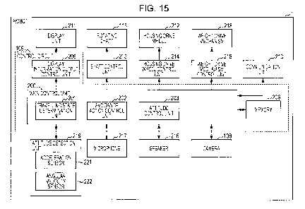
a weight drive mechanism that is provided on the frame, and that
reciprocates a weight in a predetermined direction;
an angular velocity sensor that detects angular velocity about a crosswise
direction that is perpendicular to a travelling direction of the housing; and
a control circuit that, if the control circuit determines, while the housing
is
being rotated and moved, that a rotational angle of the housing when viewed
from
front in the travelling direction changes upward beyond a predetermined angle
based on a change in the angular velocity about the crosswise direction, moves
the weight frontward in the travelling direction of the housing by a distance
corresponding to the rotational angle.
Advantageous Effects of Invention
[0007]
From the above-mentioned aspect, further improvement can be achieved.
Brief Description of Drawings
[0008]
[Fig. 1] Fig. 1 is a perspective view illustrating the external appearance of
a
robot according to an embodiment of the present disclosure.
[Fig. 2] Fig. 2 is a perspective view illustrating the inside of the robot
according to the embodiment of the present disclosure.
[Fig. 3] Fig. 3 is a side view illustrating the inside of the robot according
to
the embodiment of the present disclosure when viewed from A in Fig. 2.
[Fig. 4] Fig. 4 is a side view illustrating linear movement of the robot
according to the embodiment of the present disclosure when viewed from A in
Fig.
2.
[Fig. 5] Fig. 5 is a plan view illustrating rotation of the robot according to
the
embodiment of the present disclosure when viewed from B in Fig. 2.
[Fig. 6] Fig. 6 is a perspective view illustrating rotation of the robot
according
to the embodiment of the present disclosure.
[Fig. 7] Fig. 7 is a view illustrating a weight drive mechanism in the side
view
of Fig. 3.
2
P0466206
CA 02998310 2018-03-09
[Fig. 8A] Fig. 8A is a perspective view illustrating the operation of the
drive
mechanism for the counterweight to drive the counterweight in a predetermined
linear direction.
[Fig. 8B] Fig. 8B is a side view illustrating the operation of the
counterweight
drive mechanism to drive the counterweight in the predetermined linear
direction.
[Fig. 8C] Fig. 8C is a side view illustrating the state where the
counterweight
reciprocates in the predetermined linear direction in the side view of Fig. 3.
[Fig. 9A] Fig. 9A is a perspective view illustrating the operation of the
counterweight drive mechanism to rotate the swing arm.
[Fig. 9B] Fig. 9B is a side view illustrating the operation of the
counterweight
drive mechanism to rotate the swing arm.
[Fig. 9C] Fig. 9C is a plan view illustrating the state where the swing arm of
the robot according to the embodiment of the present disclosure rotates when
viewed from B in Fig. 2.
[Fig. 10] Fig. 10 is a side view illustrating the robot's attitude in which
the
counterweight is located to the front when viewed from A in Fig. 2.
[Fig. 11] Fig. 11 is a side view illustrating the robot's attitude in which
the
counterweight is located to the rear when viewed from A in Fig. 2.
[Fig. 12] Fig. 12 is a front view illustrating the robot's attitude in which
the
counterweight is located to the right when viewed from C in Fig. 2.
[Fig. 13] Fig. 13 is a front view illustrating the robot's attitude in which
the
counterweight is located to the left when viewed from C in Fig. 2.
[Fig. 14] Fig. 14 is a view illustrating an example of overall configuration
of a
robot system using the robot according to the embodiment of the present
disclosure.
[Fig. 15] Fig. 15 is a block diagram illustrating the robot according to the
embodiment of the present disclosure.
[Fig. 16] Fig. 16 is a flow chart illustrating an example of a main routine of
the robot according to the embodiment of the present disclosure.
[Fig. 17] Fig. 17 is a flow chart illustrating details of travelling state
determination processing (S103 in Fig. 16).
[Fig. 18] Fig. 18 is a flow chart illustrating details of moving state
determination processing (S201 in Fig. 17).
[Fig. 19] Fig. 19 is a flow chart illustrating details of attitude
determination
3
P0466206
CA 02998310 2018-03-09
processing (S203 in Fig. 17).
[Fig. 20] Fig. 20 is a view illustrating of attitude angle of the robot.
[Fig. 21] Fig. 21 is a graph illustrating the attitude determination
processing.
[Fig. 22] Fig. 22 is a flow chart illustrating details of frictional surface
travelling determination processing (S205 in Fig. 17).
[Fig. 23A] Fig. 23A is a schematic view illustrating the state of the robot
during "normal travelling" as the travelling state.
[Fig. 23B] Fig. 23B is a schematic view illustrating the state of the robot
during "frictional surface travelling" as the travelling state.
[Fig. 23C] Fig. 23C is a schematic view illustrating the state of the robot
during "uphill travelling" as the travelling state.
[Fig. 24A] Fig. 24A is a graph illustrating a shift of acceleration Az in the
vertical direction, which is exerted on the robot according to the travelling
state.
[Fig. 24B] Fig. 24B is a graph illustrating a shift of acceleration Az'
exerted
on the robot according to the travelling state.
[Fig. 25] Fig. 25 is a flow chart illustrating details of idling control
processing
(S105 in Fig. 16).
[Fig. 26A] Fig. 26A is a view illustrating the idling control processing.
[Fig. 26B] Fig. 26B is a view illustrating the idling control processing.
[Fig. 26C] Fig. 26C is a view illustrating the idling control processing.
[Fig. 26D] Fig. 26D is a view illustrating the idling control processing.
[Fig. 26E] Fig. 26E is a view illustrating the idling control processing.
[Fig. 27] Fig. 27 is a flow chart illustrating details of attitude direction
control
processing (S106 in Fig. 16).
Description of Embodiment
[0009]
(Underlying Knowledge Forming Basis of Aspect of the Present Disclosure)
As described above, PTL 1 discloses a multi-legged walking robot with four
legs, which includes an acceleration sensor and an angular velocity sensor. In
PTL 1, using two threshold values (61, 62), variances of outputs detected by
the
acceleration sensor and the angular velocity sensor are classified to three
categories to determine whether the robot acts on the ground, the robot is
lifted up,
or the robot is lifted down (for example, page 9, lines 5 to 14).
[0010]
4
P0466206
CA 02998310 2018-03-09
In contrast to this, the Inventor examines a robot having a spherical housing
and a set of drive wheels provided in contact with the inner circumferential
face of
the housing and configured to rotate the housing. A frame is provided inside
the
robot, and a display unit that displays at least a portion of the face of the
robot is
provided to the frame. The robot has no hands or legs because they may
obstruct
rotation.
[0011]
During examination of the robot, the Inventor found that the position of the
face of the travelling robot, that is, the attitude of the robot changed
depending on
the material for a floor surface on which the robot travels. For example, when
the
robot travels on a wood flooring floor having a low friction coefficient, the
robot's
face is oriented forward. Meanwhile, when the robot travels on a carpet having
a
high friction coefficient, the robot's face is oriented upward. Hence, the
Inventor
found that, even though the robot was moved by the same travel processing, the
position of the robot's face, that is, the attitude of the robot varied
depending on
the material for the floor surface rather than internal processing of the
robot.
[0012]
Such problem is not mentioned in PTL 1, and seems to have never been
addressed before.
[0013]
To solve the problem, the Inventor devised following aspects of the
invention.
[0014]
A robot according to an aspect of the present disclosure is a robot including:
a spherical housing;
a frame disposed in the housing;
a display unit that is provided on the frame, and that displays at least a
portion of a face of the robot;
a set of drive wheels that are provided on the frame, and that rotate and
move the housing while being in contact with an inner circumferential face of
the
housing;
a weight drive mechanism that is provided on the frame, and that
reciprocates a weight in a predetermined direction;
an angular velocity sensor that detects angular velocity about a crosswise
P0466206
CA 02998310 2018-03-09
direction that is perpendicular to a travelling direction of the housing; and
a control circuit that, if the control circuit determines, while the housing
is
being rotated and moved, that a rotational angle of the housing when viewed
from
front in the travelling direction changes upward beyond a predetermined angle
based on a change in the angular velocity about the crosswise direction, moves
the weight frontward in the travelling direction of the housing by a distance
corresponding to the rotational angle.
[0015]
While the housing is being rotated and moved, when it is determined that,
based on a change in the angular velocity about the crosswise direction, the
rotational angle of the housing when viewed from the front in the travelling
direction changes upward beyond a predetermined angle, it can be assumed that
the position of the display unit is moved upward as the movement of the
housing in
the travelling direction when viewed in the travelling direction is restricted
by
friction between the housing and the floor surface.
[0016]
In the aspect, in such case, the weight is moved forward in the travelling
direction of the housing by a distance corresponding to the rotational angle.
[0017]
Thereby, even when the movement of the housing in the travelling direction
is restricted by friction between the housing and the floor surface, the
display unit
oriented upward due to the restriction can be turned downward.
[0018]
As a result, the position of the robot's face, that is, the attitude of the
robot
can be prevented from unnaturally changing due to the material for the floor
surface rather than internal processing of the robot, irrespective of the same
travelling processing.
[0019]
(Embodiment)
(Overall configuration)
Fig. 1 is a perspective view illustrating the external appearance of a robot 1
according to an embodiment of the present disclosure. As illustrated in Fig.
1, the
robot 1 includes a spherical housing 101. The housing 101 is formed of a
transparent or translucent member, for example.
6
P0466206
CA 02998310 2018-03-09
[0020]
Fig. 2 is a perspective view illustrating the inside of the robot 1 according
to
the embodiment of the present disclosure.
[0021]
In Fig. 2, a frame 102 is disposed in the housing 101. The frame 102 has a
first rotating plate 103 and a second rotating plate 104. The first rotating
plate 103
is located above the second rotating plate 104. The first rotating plate 103
and the
second rotating plate 104 correspond to an example of a base.
[0022]
As illustrated in Fig. 2, a first display unit 105 and a second display unit
106
are provided on the upper face of the first rotating plate 103. A third
display unit
107 is provided on the upper face of the second rotating plate 104. For
example,
the first display unit 105, the second display unit 106, and the third display
unit 107
each are configured of a plurality of light emitting diodes. The first display
unit 105,
the second display unit 106, and the third display unit 107 can display
information
of facial expressions of the robot. Specifically, the first display unit 105,
the
second display unit 106, and the third display unit 107 individually control
lighting
of the plurality of light emitting diodes to display a portion of the face of
the robot 1
such as an eye and a mouth as illustrated in Fig. 1. In the example
illustrated in
Fig. 1, the first display unit 105 displays an image of the left eye, the
second
display unit 106 displays an image of the right eye, and the third display
unit 107
displays an image of the mouth. The images of the left eye, the right eye, and
the
mouth penetrate the main housing 101 made of a transparent or translucent
member, and are emitted to the outside.
[0023]
As illustrated in Fig. 2, a camera 108 is provided on the upper face of the
first rotating plate 103. The camera 108 acquires an image of environment
around
the robot 1. As illustrated in Fig. 1, the camera 108 constitutes a portion of
the
face of the robot 1, such as a nose. Thus, an optical axis of the camera 108
is
oriented to the front of the robot 1. Therefore, the camera 108 can take an
image
of an object to be recognized presented to the front of the robot.
[0024]
As illustrated in Fig. 2, a control circuit 109 is provided on the upper face
of
the first rotating plate 103. The control circuit 109 controls various
operations of
7
P0466206
CA 02998310 2018-03-09
the robot 1. Details of the control circuit 109 will be described later with
reference
to Fig. 15.
[0025]
A first drive wheel 110 and a second drive wheel 111 each are provided on
the lower face of the second rotating plate 104, and are in contact with the
inner
circumferential face of the housing 101. The first drive wheel 110 has a first
motor
112 that drives the first drive wheel 110. Similarly, the second drive wheel
111
has a second motor 113 that drives the second drive wheel 111. That is, the
first
drive wheel 110 and the second drive wheel 111 are driven by the respective
independent motors. Details of the operation of the robot 1 driven by the
first drive
wheel 110 and the second drive wheel 111 will be described later. The first
drive
wheel 110 and the second drive wheel 111 constitute a pair of drive wheels.
[0026]
Fig. 3 is a side view illustrating the inside of the robot 1 according to the
embodiment of the present disclosure when viewed from A in Fig. 2. In Fig. 3,
a
counterweight 114 (an example of a weight) is provided between the first
rotating
plate 103 and the second rotating plate 104. The counterweight 114 is located
somewhat below the center of the housing 101. Accordingly, the center of
gravity
of the robot 1 is located below the center of the housing 101. This can
stabilize
the operation of the robot 1. Viewing from A means that the robot 1 is viewed
from
right toward left.
[0027]
As illustrated in Fig. 3, to drive the counterweight 114, the robot 1 includes
a
guide shaft 115 that specifies the moving direction of the counterweight 114,
a
swing arm 116 that specifies the position of the rotating direction of the
counterweight 114, a rotational motor 117 that rotates the swing arm 116, a
rotating shaft 118 that connects the swing arm 116 to the rotational motor
117, a
belt 119 used to drive the counterweight 114 (Figs. 8A and 8B), a motor pulley
120
that is in contact with the belt 119 (Figs. 8A and 8B), and a weight drive
motor not
illustrated that rotates the motor pulley 120. In this embodiment, the drive
motor is
built in the counterweight 114. Details of the operation of the robot 1 driven
by the
counterweight 114 will be described later.
[0028]
The rotating shaft 118 extends perpendicular to a drive axis of the first
drive
8
P0466206
CA 02998310 2018-03-09
wheel 110 and the second drive wheel 111. The rotating shaft 118 corresponds
to
an example of a shaft provided on the frame 102. When viewed from front, the
first drive wheel 110 and the second drive wheel 111 get gradually away from
each other toward the ground. In this case, the drive axis of the first drive
wheel
110 and the second drive wheel 111 is, for example, a virtual axis connecting
the
centers of the first drive wheel 110 and the second drive wheel 111 to each
other.
When the first drive wheel 110 and the second drive wheel 111 are provided in
parallel to each other when viewed from front, the actual drive axis becomes
the
drive axis of the first drive wheel 110 and the second drive wheel 111.
[0029]
The robot 1 further includes a power source not illustrated and a
microphone 217 (Fig. 15). The robot 1 is charged by a charger not illustrated.
The microphone 217 acquires sound of environment around the robot 1.
[0030]
Next, the operation of the robot 1 using the first drive wheel 110 and the
second drive wheel 111 will be described with reference to Figs. 4 to 6.
[0031]
Fig. 4 is a side view illustrating linear movement of the robot 1 according to
the embodiment of the present disclosure when viewed from A in Fig. 2. Fig. 5
is
a plan view illustrating the rotation of the robot 1 according to the
embodiment of
the present disclosure when viewed from B in Fig. 2. Fig. 6 is a perspective
view
illustrating the rotation of the robot 1 according to the embodiment of the
present
disclosure. Looking from B means that the robot is viewed from above.
[0032]
As illustrated in Fig. 4, when the first drive wheel 110 and the second drive
wheel 111 are rotated forward, the housing 101 rotates forward due to the
motive
power. Thereby, the robot 1 moves forward. Conversely, when the first drive
wheel 110 and the second drive wheel 111 are rotated rearward, the robot 1
moves rearward.
[0033]
As illustrated in Figs. 5 and 6, when the first drive wheel 110 and the second
drive wheel 111 are rotated in opposite directions, the housing 101 rotates
about a
vertical axis passing through the housing due to the motive power. That is,
the
robot 1 rotates clockwise or counterclockwise at the spot. In this manner, the
9
P0466206
CA 02998310 2018-03-09
robot 1 moves forward, moves rearward, or rotates.
[0034]
Next, the basic operation of the robot 1 using the counterweight 114 will be
described with reference to Figs. 7 to 9C.
[0035]
Fig. 7 is a view illustrating the weight drive mechanism in the side view of
Fig. 3. Fig. 8A is a perspective view illustrating the operation of the drive
mechanism for the counterweight 114 to drive the counterweight 114 in a
predetermined linear direction. Fig. 8B is a side view illustrating the
operation of
the drive mechanism for the counterweight 114 to drive the counterweight 114
in a
predetermined linear direction. Fig. 8C is a side view illustrating the state
where
the counterweight 114 reciprocates in a predetermined linear direction in the
side
view of Fig. 3. Fig. 9A is a perspective view illustrating the operation of
the drive
mechanism for the counterweight 114 to rotate the swing arm 116. Fig. 9B is a
side view illustrating the operation of the weight drive mechanism to rotate
the
swing arm 116. Fig. 9C is a plan view illustrating the state where the swing
arm
116 of the robot 1 according to the embodiment of the present disclosure
rotates
when viewed from B in Fig. 2.
[0036]
As illustrated in Fig. 7, the center of the swing arm 116 is a default
position
of the counterweight 114. When the counterweight 114 is located at the center
of
the swing arm 116, the first rotating plate 103 and the second rotating plate
104
become substantially parallel to a floor surface, to form the face of the
robot 1, for
example, eyes, a nose, and mouth are oriented in a default direction.
[0037]
As illustrated in Figs. 8A and 8B, the weight drive motor not illustrated
built
in the counterweight 114 rotates the motor pulley 120 coupled to the weight
drive
motor. The rotated motor pulley 120 rolls on the belt 119, such that the
counterweight 114 moves in the swing arm 116. The counterweight 114
reciprocates in the linear direction in the swing arm 116 by changing the
rotating
direction of the motor pulley 120, that is, the driving direction of the
weight drive
motor.
[0038]
As illustrated in Fig. 8C, the counterweight 114 reciprocates in the swing
P0466206
CA 02998310 2018-03-09
arm 116 along the guide shaft 115 in the linear direction.
[0039]
As illustrated in Figs. 9A and 9B, the rotational motor 117 rotates the
rotating shaft 118 to rotate the swing arm 116 connected to the rotating shaft
118
(Fig. 3).
[0040]
As illustrated in Fig. 9C, the swing arm 116 can be rotated clockwise and
counterclockwise.
[0041]
Details of the operation of the robot 1 using the counterweight 114 will be
described with reference to Figs. 10 to 13. Fig. 10 is a side view
illustrating the
attitude of the robot 1 in which the counterweight 114 is located to the front
when
viewed from A in Fig. 2. Fig. 11 is a side view illustrating the attitude of
the robot 1
in which the counterweight 114 is located to the rear when viewed from A in
Fig. 2.
Fig. 12 is a front view illustrating the attitude of the robot 1 in which the
counterweight 114 is located to the right when viewed from C in Fig. 2. Fig.
13 is a
front view illustrating the attitude of the robot 1 in which the counterweight
114 is
located to the left when viewed from C in Fig. 2. Looking from C means that
the
robot 1 is viewed from the front.
[0042]
As illustrated in Fig. 10, in the state where the swing arm 116 is
perpendicular to the front of the robot 1, when the counterweight 114 is moved
from the default position toward one end (left end in Fig. 10) of the swing
arm 116,
that is, the front, robot 1 leans to the front as represented by an arrow 121.
As
illustrated in Fig. 11, in the state where the swing arm 116 is perpendicular
to the
front of the robot 1, when the counterweight 114 is moved from the default
position
toward the other end (right end in Fig. 11) of the swing arm 116, that is, the
front,
the robot 1 leans to the rear as represented by an arrow 122. Therefore, in
the
state where the swing arm 116 is perpendicular to the front of the robot 1,
when
the counterweight 114 reciprocates from one end to the other end of the swing
arm 116, the robot 1 alternately tilts forward and rearward as represented by
the
arrow 121 and the arrow 122, respectively. That is, the robot 1 rotates with a
predetermined angle in the vertical direction.
[0043]
11
P0466206
CA 02998310 2018-03-09
As described above, the first display unit 105, the second display unit 106,
and the third display unit 107 express a portion of the face of the robot 1,
such as
eyes and a mouth. For example, the robot 1 can be alternately tilted forward
and
rearward using the counterweight 114, as if the robot 1 is short of breath or
sleepy.
By performing this control when remaining power of the power source reaches a
predetermined value or less, the robot 1 can notify the user that remaining
power
of the power source is small, without displaying information on the remaining
power, which is unrelated to the face, on the first display unit 105, the
second
display unit 106, and the third display unit 107.
[0044]
As illustrated in Fig. 12, in the state where the swing arm 116 is parallel to
the front of the robot 1, when the counterweight 114 is moved from the default
position toward one end (right end in Fig. 12) of the swing arm 116, that is,
the
right, robot 1 leans to the right as represented by an arrow 123. As
illustrated in
Fig. 13, in the state where the swing arm 116 is parallel to the front of the
robot 1,
when the counterweight 114 is moved from the default position toward the other
end (left end in Fig. 13) of the swing arm 116, that is, the left, the robot 1
leans to
the left as represented by an arrow 124. Therefore, in the state where the
swing
arm 116 is parallel to the front of the robot 1, when the counterweight 114
reciprocates from one end to the other end of the swing arm 116, the robot 1
alternately tilts right and left as represented by the arrow 123 and the arrow
124,
respectively. That is, the robot 1 swings side-to-side with a predetermined
angle.
[0045]
As described above, the first display unit 105, the second display unit 106,
and the third display unit 107 express a portion of the face of the robot 1,
such as
eyes and a mouth. For example, the robot 1 can be alternately tilted rightward
and
leftward using the counterweight 114, as if the robot 1 feels good or is
thinking
deeply.
[0046]
Fig. 14 is a view illustrating an example of overall configuration of a robot
system 1500 using the robot 1 according to the embodiment of the present
disclosure. The robot system 1500 includes a cloud server 3, a portable
terminal 4,
and the robot 1. The robot 1 is connected to the Internet via Wifi (registered
trademark), and to the cloud server 3. The robot 1 is also connected to the
12
P0466206
CA 02998310 2018-03-09
portable terminal 4 via Wifi (registered trademark), for example. As an
example, a
user 1501 is a child, and users 1502, 1503 are parents of the child.
[0047]
For example, an application cooperating with the robot 1 is installed on the
portable terminal 4. The portable terminal 4 can issue various instructions to
the
robot 1 using the application, and display the image recognition result
described
referring to Fig. 14.
[0048]
When receiving a request to read a picture book to the child from the
portable terminal 4, the robot 1 reads the picture book aloud to the child.
When
accepting a question during reading of the picture book, the robot 1 transmits
the
question to the cloud server 3, receives an answer to the question from the
cloud
server 3, and makes the answer.
[0049]
As described above, the user 1501 can treat the robot 1 like a pet, and learn
language through communication with the robot 1.
[0050]
Next, details of an internal circuit of the robot 1 according to the
embodiment of the present disclosure will be described with reference to Fig.
15.
Fig. 15 is a block diagram illustrating the robot 1 according to the
embodiment of
the present disclosure.
[0051]
As illustrated in Fig. 15, the robot 1 includes the control circuit 109, a
display
unit 211, a shaft control unit 213, the rotating shaft 118, a housing drive
wheel
control unit 214, a housing drive wheel 212, a weight drive mechanism control
unit
215, a weight drive mechanism 218, an attitude detection unit 219, the
microphone
217, a speaker 216, the camera 108, and a communication unit 210.
[0052]
The control circuit 109 is configured of a computer including a memory 206,
a main control unit 200 configured of a processor such as a CPU, a display
information output control unit 205, and a timer not illustrated that checks
the time.
[0053]
The memory 206 is configured of, for example, a nonvolatile rewritable
storage device that stores a program for controlling the robot 1 and so on.
13
P0466206
CA 02998310 2018-03-09
[0054]
The main control unit 200 executes the control program for controlling the
robot 1, which is stored in the memory 206. Thereby, the main control unit 200
functions as a travelling state determination unit 201, an avoidance action
control
unit 202, and an attitude control unit 203.
[0055]
The attitude detection unit 219 includes an acceleration sensor 221 and an
angular velocity sensor 222.
[0056]
For example, the acceleration sensor 221 is configured of a three-axis
acceleration sensor attached to the first rotating plate 103. As illustrated
in Fig. 2,
the acceleration sensor 221 detects an acceleration (an example of a first
acceleration) in a vertical direction (Z direction), an acceleration in a
crosswise
direction (X direction), and an acceleration (an example of second
acceleration) in
a front-rear direction (Y direction). The vertical direction is orthogonal to
the
principal plane of the first rotating plate 103. The crosswise direction is a
right-left
direction when the robot 1 is viewed from the front. The front-rear direction
is
orthogonal to the vertical direction and the crosswise direction. Accordingly,
the
front-rear direction is parallel to the principal plane of the first rotating
plate 103.
[0057]
The acceleration sensor 221 outputs the detected acceleration in the three
directions to the main control unit 200. The acceleration sensor 221 and the
angular velocity sensor 222 may be attached to the lower face of the first
rotating
plate 103, or the upper or lower face of the second rotating plate 104, rather
than
the upper face of the first rotating plate 103.
[0058]
The angular velocity sensor 222 detects the angular velocity of the robot 1
about the crosswise direction, that is, the angular velocity of the robot 1 in
a pitch
direction. Further, the angular velocity sensor 222 detects the angular
velocity of
the robot 1 about the vertical direction, that is, the angular velocity of the
robot 1 in
a yaw direction. Further, the angular velocity sensor 222 detects the angular
velocity of the robot 1 about the front-rear direction, that is, the angular
velocity of
the robot 1 in a roll direction.
[0059]
14
P0466206
CA 02998310 2018-03-09
The microphone 217 is provided on the frame 102, converts sound into an
electric signal, and outputs the electric signal to the main control unit 200.
For
example, the microphone 217 may be attached to the upper face of the first
rotating plate 103, or may be attached to the upper face of the second
rotating
plate 104. The main control unit 200 recognizes whether or not the user's
voice is
present in the sound acquired by the microphone 217, and stores voice
recognition results in the memory 206 to manage the voice recognition results.
The main control unit 200 compares voice recognition data stored in the memory
206 with the acquired sound, and recognizes speech contents and the user who
spoke.
[0060]
The speaker 216 is provided on the frame 102 such that an output face is
oriented to the front, and converts the electric signal of sound into physical
vibrations. The main control unit 200 outputs predetermined vice via the
speaker
216 to enable the robot 1 to speak.
[0061]
As described above with reference to Fig. 2, the camera 108 takes an
image in front of the robot 1 (Y direction), and outputs the image
(hereinafter
referred to as taken image) to the main control unit 200. The main control
unit 200
recognizes presence/absence, position, and size of the user's face from the
taken
image acquired by the camera 108, and stores face recognition results in the
memory 206 to manage the face recognition results.
[0062]
The main control unit 200 generates a command based on the voice
recognition result and the face recognition result, and outputs the command to
the
display information output control unit 205, the shaft control unit 213, the
housing
drive wheel control unit 214, the weight drive mechanism control unit 215, and
the
communication unit 210.
[0063]
According to the command from the main control unit 200, the display
information output control unit 205 displays information on facial expression
of the
robot 1 on the display unit 211. The display unit 211 is configured of the
first
display unit 105, the second display unit 106, and the third display unit 107,
which
are described with reference to Fig. 2.
P0466206
CA 02998310 2018-03-09
[0064]
According to the command from the main control unit 200, the shaft control
unit 213 rotates the rotating shaft 118 described with reference to Figs. 9A
and 9B.
The shaft control unit 213 is configured of the rotational motor 117 described
with
reference to Figs. 9A and 9B.
[0065]
According to the command from the main control unit 200, the housing drive
wheel control unit 214 operates the housing drive wheel 212 of the robot 1.
The
housing drive wheel control unit 214 is configured of the first motor 112 and
the
second motor 113, which are described with reference to Fig. 2. The housing
drive wheel 212 is configured of the first drive wheel 110 and the second
drive
wheel 111, which are described with reference to Fig. 2. The housing drive
wheel
212 corresponds to an example of a set of drive wheels.
[0066]
According to the command from the main control unit 200, the weight drive
mechanism control unit 215 operates the weight drive mechanism 218 of the
robot
1. The weight drive mechanism control unit 215 is configured of a weight drive
motor not illustrated built in the counterweight 114. The weight drive
mechanism
218 is configured of the guide shaft 115, the swing arm 116, the rotational
motor
117, the belt 119, the motor pulley 120, and the weight drive motor not
illustrated,
which are described with reference to Figs. 3, 8A, and 8B.
[0067]
The communication unit 210 is configured of a communication device
capable of connecting the robot 1 to the cloud server 3 (Fig. 14). Examples of
the
communication unit 210 include, but are not limited to, a wireless LAN
communication device such as Wifi (registered trademark). According to a
command from the main control unit 200, the communication unit 210
communicates with the cloud server 3.
[0068]
(Main routine)
Fig. 16 is a flow chart illustrating an example of a main routine of the robot
1
according to the embodiment of the present disclosure.
[0069]
The flow chart in Fig. 16 is periodically performed at sampling interval At.
16
P0466206
CA 02998310 2018-03-09
First, the main control unit 200 checks whether or not the first motor 112 and
the
second motor 113 rotate (S101). Here, for example, the main control unit 200
differentiates rotational angles of the first motor 112 and the second motor
113,
which are detected by respective encoders of the first motor 112 and the
second
motor 113 to find rotational rates of the first motor 112 and the second motor
113.
The main control unit 200 may determine that the robot 1 is "not rotating",
that is,
"suspended" when both of the found rotational rates of the first motor 112 and
the
second motor 113 are substantially 0, and determine that the robot 1 is
"rotating",
when at least one of the rotational rates of the first motor 112 and the
second
motor 113 is not substantially 0.
[0070]
Next, if it is determined that the robot is "rotating" in S101 (YES in S102),
the main control unit 200 proceeds the processing to S103. Meanwhile, if it is
determined that the robot is "not rotating" in S101 (NO in S102), the main
control
unit 200 finishes the processing.
[0071]
In S103, the travelling state determination unit 201 executes travelling state
determination processing. Details of the travelling state determination
processing
will be described later with reference to Fig. 17.
[0072]
In 8104, the processing branches depending on the result of the travelling
state determination processing (S103). That is, if the result of the
travelling state
determination processing indicates "idling" ("idling" in S104), the avoidance
action
control unit 202 executes idling control processing (S105), and finishes the
processing. Details of the idling control processing will be described later
with
reference to Fig. 25. If the result of the travelling state determination
processing
indicates "uphill travelling" ("uphill travelling" in S104), the main control
unit 200
finishes the processing.
[0073]
If the result of the travelling state determination processing indicates
"frictional surface travelling" (frictional surface travelling" in S104), the
attitude
control unit 203 executes attitude control processing (S106), and finishes the
processing. Details of the attitude control processing will be described later
with
reference to Fig. 27.
17
P0466206
CA 02998310 2018-03-09
[0074]
The travelling state refers to the travelling state of the robot 1 while the
first
motor 112 and the second motor 113 are rotating, and includes "idling",
"uphill
travelling", "frictional surface travelling", and "normal travelling".
[0075]
Given that the friction coefficient of the wood flooring floor is a typical
friction
coefficient, the "frictional surface travelling" refers to the state where the
robot 1 is
travelling on the floor surface having a friction coefficient higher than the
typical
friction coefficient by a certain value (for example, carpet). In this
embodiment, the
robot 1 is designed such that the Y direction becomes parallel to the
travelling
direction in Fig. 2 when the robot 1 is travelling on the wood flooring floor
having
the typical friction coefficient at a predetermined target rate. Given that
the
position of the first to third display units 105 to 107 at this time is a
reference
position of the face of the robot 1, during the frictional surface travelling,
the angle
that forms the Y direction with the travelling direction due to friction
increases,
turning the face of the robot 1 above the reference position. In the attitude
control
processing (S106), the face orientation is returned to the reference position.
[0076]
If the result of the travelling state determination processing is "normal
travelling" ("normal travelling" in S104), the main control unit 200 finishes
processing. The "normal travelling" refers to the state where the robot 1 is
travelling on a flat floor surface having the typical friction coefficient.
The "uphill
travelling" refers to the state where the robot 1 is going uphill. The
"idling" refers
to the state where the first motor 112 and the second motor 113 are rotating,
but
the robot 1 is static.
[0077]
(Travelling state determination processing)
Fig. 17 is a flow chart illustrating details of the travelling state
determination
processing (S103 in Fig. 16). First, the travelling state determination unit
201
executes moving state determination processing (S201). Details of the moving
state determination processing will be described later with reference to Fig.
18.
[0078]
If the result of the moving state determination processing is "moving state"
(YES in S202), the travelling state determination unit 201 executes attitude
change
18
P0466206
CA 02998310 2018-03-09
determination processing (S203). Details of the attitude change determination
processing will be described later with reference to Fig. 19. Meanwhile, if
the
result of the moving state determination processing does not indicate "moving
state" (NO in S202), the travelling state determination unit 201 determines
the
travelling state of the robot 1 as "idling" (S210), and the processing returns
to
8104 in Fig. 16.
[0079]
If the result of the attitude change determination processing indicates
"attitude change" (YES in S204), the travelling state determination unit 201
executes frictional surface travelling determination processing (S205).
Details of
the frictional surface travelling determination processing will be described
later
with reference to Fig. 22. Meanwhile, if the result of the attitude change
determination processing indicates "no attitude change" (NO in S204), the
travelling state determination unit 201 determines the travelling state of the
robot 1
as "normal travelling" (S209), and the processing returns to S104 in Fig. 16.
[0080]
If the result of the frictional surface travelling determination processing
does
not indicate "frictional surface travelling" (YES in S206), the travelling
state
determination unit 201 determines the travelling state as "uphill travelling"
(S207),
and the processing returns to S104 in Fig. 16.
[0081]
Meanwhile, if the result of the frictional surface travelling determination
processing indicates "frictional surface travelling" (NO in S206), the
travelling state
determination unit 201 determines the travelling state of the robot 1 as
"frictional
surface travelling" (S208), and the processing returns to S104 in Fig. 16.
[0082]
(Moving state determination processing)
Fig. 18 is a flow chart illustrating details of moving state determination
processing (S201 in Fig. 17). First, the travelling state determination unit
201
acquires acceleration A from the acceleration sensor 221 (S301).
[0083]
Next, the travelling state determination unit 201 differentiates acceleration
Ay in the Y direction among the acceleration A acquired in S301 to calculate
current rate Vy of the robot 1 in the Y direction (S302).
19
P0466206
CA 02998310 2018-03-09
[0084]
Next, if the current rate Vy of the robot 1 in the Y direction is larger than
0
(YES in S303), the travelling state determination unit 201 determines that the
robot
1 is "moving state" (S304). The "moving state" refers to the state where the
first
motor 112 and the second motor 113 do not idle and the robot 1 is actually
travelling. Specifically, "moving state" includes the above-mentioned "uphill
travelling", "frictional surface travelling", and "normal travelling".
Meanwhile, if the
current rate Vy of the robot 1 in the Y direction is 0 (NO in 5303), the
travelling
state determination unit 201 returns the processing to S202 in Fig. 17. In the
case
if NO in S303, NO is selected in S202 in Fig. 17, and the travelling state of
the
robot 1 is determined as "idling" (S210).
[0085]
(Attitude determination processing)
Fig. 19 is a flow chart illustrating details of attitude determination
processing
(S203 in Fig. 17). First, the travelling state determination unit 201 acquires
the
acceleration A from the acceleration sensor 221, and angular velocity 0.) from
the
angular velocity sensor 222 (S401).
[0086]
Next, the travelling state determination unit 201 calculates an amount of
change AO of attitude angle 0 that is the angle of the robot 1 in the pitch
direction
from angular velocity wp in the pitch direction among the angular velocity w
acquired in S401 (S402). In this case, the travelling state determination unit
201
may calculate an amount of change AO (= wp x At) by multiplying the sampling
interval At by the angular velocity op acquired in S401. That is, the amount
of
change AO refers to an amount of change in attitude angle 0 at the sampling
interval At.
[0087]
Fig. 20 is a view illustrating the attitude angle 0 of the robot 1. Fig. 20
illustrates the state having the attitude angle 0 of 0. As illustrated in Fig.
20, the
attitude angle 0 refers to the angle that forms the Y direction with a
reference
direction Dl. The reference direction D1 is a direction acquired by projecting
the
travelling direction of the robot 1 onto a horizontal surface El.
[0088]
P0466206
CA 02998310 2018-03-09
Next, the travelling state determination unit 201 calculates the current
attitude angle 0 (S403). In this case, given that the current attitude angle 0
is the
attitude angle 0(t), and the attitude angle 0 calculated at the previous
sampling
point is the attitude angle 0(t - At), the travelling state determination unit
201 may
calculate the attitude angle 0 according to the equation: 0 (t) = 0 (t - At) +
AO.
[0089]
Next, the travelling state determination unit 201 excludes a gravitational
acceleration component (g x cos0) from the acceleration Az acquired in S401 to
calculate acceleration Az' (= Az- (-g x cos0)) (S404). Values of the
acceleration
Az' calculated in S404 for at least a certain period are stored in the memory
to be
used in below-mentioned frictional surface travelling determination processing
(Fig.
22). The acceleration Az' is an example of a second value. The symbol "-"
added
to g x cos means that upward is represented by plus, and downward is
represented by minus.
[0090]
Next, the travelling state determination unit 201 determines whether or not
the attitude angle 0 calculated in S403 reaches a predetermined lower limit
angle
OL (S405). Fig. 21 is a graph illustrating the attitude determination
processing, a
vertical axis represents the angular velocity cop (degree/sec) in the pitch
direction,
and a horizontal axis represents time. In Fig. 21, dotted lines drawn in
parallel to
the vertical axis represent sampling points. A waveform W1 indicates a shift
of the
angular velocity cop with time. Since an area between the waveform W1 and the
time axis represents an integrated value of the angular velocity wp, the area
refers
to the attitude angle 0. The lower limit angle OL is the attitude angle 0 that
satisfies
a condition for starting timekeeping of determination time TD.
[0091]
If the attitude angle 0 is the lower limit angle OL or more (YES in S405), the
travelling state determination unit 201 increments a count for keeping the
determination time TD (S406). Since the flow chart of Fig. 19 is performed
every
sampling interval At, the count is incremented every the sampling interval At.
As
illustrated in Figs. 20 and 21, in the attitude determination processing, when
the
attitude angle 0 exceeds the lower limit angle OL, keeping of the
determination
time TD is started. This is due to that, during frictional surface travelling
and uphill
21
P0466206
CA 02998310 2018-03-09
travelling of the robot 1, the attitude angle 0 is assumed to keep the lower
limit
angle OL or more. Therefore, the lower limit angle OL adopts a minimum value
of
the attitude angle 0 of the robot 1 assumed during frictional surface
travelling or
uphill travelling of the robot 1.
[0092]
Meanwhile, if the attitude angle 0 is less than the lower limit angle OL (NO
in
S405), the travelling state determination unit 201 proceeds the processing to
S411.
[0093]
In S407, if the count reaches determination time TD (YES in S407), the
travelling state determination unit 201 determines the result of the attitude
determination processing as "attitude change" (S408), and finishes keeping of
the
determination time TD (S409). In this case, the travelling state determination
unit
201 may reset the count of the determination time TD to 0.
[0094]
It is supposed that the robot 1 performs frictional surface travelling and
uphill travelling while keeping a certain level of attitude angle 0. Thus, in
the
attitude change determination processing, if the condition that the attitude
angle 0
keeps the lower limit angle OL or more for the determination time TD is
satisfied,
the travelling state determination unit 201 determines that the attitude of
the robot
1 has changed. This can prevent the travelling state determination unit 201
from
wrongly determining that the robot 1 is conducting frictional surface
travelling or
uphill travelling due to a temporal change in the attitude angle 0 caused, for
example, when the robot 1 runs onto a garbage on the wood flooring floor.
[0095]
Next, the travelling state determination unit 201 sets an attitude control
angle OC to the current attitude angle 0 (S410), and returns the processing to
S204 in Fig. 17. In this case, referring to Fig. 20, the attitude control
angle OC
becomes the attitude angle 0 of the robot 1 at an end time at an end point EP
of
the determination time TD (Fig. 21). That is, the attitude control angle OC
becomes the lower limit angle OL + amount of change O_TD of the attitude angle
0
for the determination time TD. Accordingly, even when the attitude angle 0
continues to increase after the end point EP, the attitude control angle OC is
the
attitude angle 0 at the end point EP.
22
P0466206
CA 02998310 2018-03-09
[0096]
In S411, if the determination period TD is being checked (YES in S411), the
travelling state determination unit 201 finishes checking of the determination
period TD (S412), and proceeds the processing to S413, and if the
determination
period TD is not being checked (NO in S411), the and proceeds the processing
to
S413. In S412, as in S409, the travelling state determination unit 201 may
reset
the count of the determination time TD to 0.
[0097]
In S413, the travelling state determination unit 201 determines the result of
the attitude determination processing as "no attitude change", and returns the
processing to S204 in Fig. 17.
[0098]
When the robot 1 travels on a floor surface such as carpet having yarns of
varied directions and lengths, the attitude angle 0 may repeatedly fluctuate
up and
down around the lower limit angle OL. In this case, despite that the attitude
angle
0 is not continuously kept at the lower limit angle OL or more, the travelling
state
determination unit 201 may determine "attitude change" due to the accumulated
value of the count. To present this, the processing in S411, S411 is provided.
This can prevent the value in the count from being accumulated when the
attitude
angle 0 repeatedly fluctuates up and down around the lower limit angle OL. As
a
result, when the attitude angle 0 is not continuously kept at the lower limit
angle OL
or more, the travelling state determination unit 201 can be prevented from
wrongly
determining "attitude change".
[0099]
The attitude determination processing will be summarized with reference to
Fig. 21. The travelling state determination unit 201 acquires the angular
velocity
wp at the sampling interval At, and adds up the acquired angular velocity cop
to
monitor the current attitude angle 0. Then, when the attitude angle 0 reaches
the
lower limit angle OL, the travelling state determination unit 201 determines a
start
point SP when keeping of the determination time TD is started arrives, and
starts
to keep the determination time TD. Then, if the attitude angle 0 becomes less
than
the lower limit angle OL for the determination time TD, the travelling state
determination unit 201 selects NO in S405 in Fig. 19 to determine the result
as "no
23
P0466206
CA 02998310 2018-03-09
attitude change" (S411). Meanwhile, if the attitude angle 0 keeps the lower
limit
angle 01_ or more by the end point EP in the determination time TD, the
travelling
state determination unit 201 determines the result as "attitude change" (S408
in
Fig. 19).
[0100]
(Frictional surface travelling determination processing)
Fig. 22 is a flow chart illustrating details of frictional surface travelling
determination processing (S205 in Fig. 17). First, the travelling state
determination unit 201 determines whether or not the acceleration Az' (= Az +
g x
cos0) calculated in S404 in Fig. 19 is continuously less than a reference
value (an
example of a first change width) for a certain time (S501), if the
acceleration Az' is
continuously less than the reference value (YES in S501), the travelling state
determination unit 201 determines the result as "frictional surface
travelling"
(S502). Meanwhile, if the acceleration Az' is not continuously less than the
reference value for the certain time (NO in S501), the travelling state
determination
unit 201 determines the result as "frictional surface travelling (S503). When
the
processing in Fig. 22 is finished, the processing returns to S206 in Fig. 17.
[0101]
Fig. 23A is a schematic view illustrating the state of the robot 1 during
"normal travelling". Fig. 23B is a schematic view illustrating the state of
the robot 1
during "frictional surface travelling". Fig. 23C is a schematic view
illustrating the
state of the robot 1 during "uphill travelling".
[0102]
Fig. 24A is a graph illustrating a shift of the acceleration Az exerted on the
robot 1 in the vertical direction with time according to the travelling state.
Fig. 24B
is a graph illustrating a shift of the acceleration Az' exerted on the robot 1
with time
according to the travelling state. In Fig. 24A, a vertical axis represents the
acceleration Az, and a horizontal axis represents time. In Fig. 24B, a
vertical axis
represents the acceleration Az', and a horizontal axis represents time. In
Figs.
24A and 24B, waveforms W211, W221 represent accelerations Az, Az',
respectively, exerted when the travelling state is switched from "normal
travelling:
time Ti" to "frictional surface travelling: time T2", and waveforms W212, W222
represent accelerations Az, Az', respectively, exerted when the travelling
state is
24
P0466206
CA 02998310 2018-03-09
switched from "normal travelling: time T1" to "uphill travelling: time T2".
[0103]
Referring to Fig. 23A, during "normal travelling", the robot 1 travels on a
flat
floor face FA having the typical friction coefficient at a predetermined
target rate.
During normal travelling, since the robot 1 is designed such that the Y
direction is
parallel to the floor face FA, the Y direction becomes parallel to the
travelling
direction D2 of the robot 1. In this case, since a gravitational component (-
g) is
added to the robot 1 in the Z direction, as represented by time T1 in Fig.
24A, the
acceleration Az both in the waveforms W211, W212 is -g. Accordingly, the
acceleration Az' becomes 0 according to Az (= -g) - (-g). For this reason, as
illustrated in Fig. 24B, in time Ti, the acceleration Az' both in the
waveforms W221,
W222 keeps substantially 0. Pulsation of the waveforms in Figs. 24A and 24B is
caused by vibrations of the floor and the like.
[0104]
Referring to Fig. 23B, during frictional surface travelling, due to friction
on a
floor face FB, the robot 1 is oriented upward with the attitude angle 0 with
respect
to the travelling direction D2 that is parallel to the floor face FB, and
travels on the
floor face FB at a rate V in the travelling direction D2. Accordingly, during
frictional
surface travelling, the robot 1 has rate Vy in the Y direction and rate Vz in
the Z
direction.
[0105]
Immediately after the robot 1 enters to the floor face FB, the rate V
decreases one by friction and so on, but the robot 1 is controlled to travel
at a
uniform rate and thus, the rate V returns to target rate soon. In a transient
period
during which the robot 1 enters to the floor face FB and the rate V returns to
the
target rate, acceleration az caused by a change in the rate Vz is added to the
robot 1 in the Z direction.
[0106]
In the transient period, since the attitude angle 0 of the robot 1 increases
from 0 degree to an angle corresponding to the friction coefficient of the
floor face
FB, the acceleration of -g x cos0 caused by gravity in addition to the
acceleration
az is added to the robot 1 in the Z direction. Thus, the acceleration Az
becomes
az - g x cos0. Accordingly, the acceleration Az' becomes az (Az' = az - g x
cos() -
P0466206
CA 02998310 2018-03-09
(-g x cos 0)). In the transient period, since the rate Vz decreases and then,
increases, the acceleration az changes in the - direction and then, changes in
the
+ direction. Therefore, in the transient period of frictional surface
travelling, as
represented by the waveform W221 in Fig. 24B, the waveform of acceleration Az'
protrudes downward.
[0107]
Referring to Fig. 23C, during uphill travelling, given that the inclination
angle
of a sloping road FC is a, the robot 1 travels on the sloping road FC at the
rate V
while being oriented upward with the inclination angle a with respect to the
reference direction Dl. In this case, since the Y direction of the robot 1
becomes
parallel to the sloping road FC (travelling direction D2), the robot 1 has
only the
rate component in the Y direction, and has no rate component in the Z
direction.
[0108]
Thus, in the transient period during the robot 1 enters to the sloping road FC
and runs onto the sloping road FC, the acceleration az caused by the rate Vz
is
not added to the robot 1 as in frictional surface travelling, and the
acceleration of -
g x cos0 caused by gravity is added to the robot I. Accordingly, as
represented by
the waveform W212 in Fig. 24A, in the transient period of uphill travelling,
the
acceleration Az gradually increases from the - side to the + side according to
cos0.
[0109]
As described above, during uphill travelling, since only the acceleration of -
g
x cos 0 caused by gravity is added to the acceleration Az, the acceleration
Az'
becomes 0 (Az' = -g x cos - (-g x cos0)). Accordingly, as represented by the
waveform W222 in Fig. 24B, the acceleration Az' keeps substantially 0.
[0110]
Accordingly, if the acceleration Az' is kept to be less than a reference value
for a certain time, the travelling state determination unit 201 determines the
travelling state of the robot 1 as frictional surface travelling (YES in
S501).
Meanwhile, if the acceleration Az' is not kept to be less than the reference
value
for the certain time, the travelling state determination unit 201 determines
the
travelling state of the robot 1 as uphill travelling (NO in S501).
[0111]
In S404 in Fig. 19, the accelerations Az' for a certain time are stored in the
26
P0466206
CA 02998310 2018-03-09
memory. Thus, given that the processing in S501 starts at a time P24 as
illustrated in Fig. 24, the travelling state determination unit 201 can
calculate the
waveform of the acceleration Az' from values of the acceleration Az'
calculated
during a certain time T24 starting from the time P24. When the waveform
protrudes downward as represented by the waveform W221, the acceleration Az'
is kept to be less than the reference value for the certain time, and the
travelling
state is determined as frictional surface travelling. Meanwhile, when the
waveform
is flat as represented by the waveform W222, the acceleration Az' is kept at
the
reference value or more for the certain time, the travelling state is
determined as
uphill travelling. The certain time T24 may be the above-described transient
period. The reference value may be a value that is lower than 0 by a certain
margin.
[0112]
(Idling processing)
Fig. 25 is a flow chart illustrating details of idling control processing
(S105 in
Fig. 16). Figs. 26A, 26B, 26C, 26D, and 26E are views illustrating the idling
control processing. Figs. 26A, 26B, 26C, 26D, and 26E illustrate the robot 1
when
viewed from above. In Figs. 26B, 26C, 26D, and 26E, the step number expressed
as "S + numeral value" corresponds to the step number expressed as "S +
numeral value". In Fig. 26A, an obstacle 2600 obstructs movement of the robot
1,
and the robot 1 is idling. In Fig. 26A, the obstacle 2600 is a power line and
however, it is merely an example. For example, an object such as a wall may be
the obstacle 2600.
[0113]
First, as the robot 1 is idling due to the presence of the obstacle 2600 as
illustrated in Fig. 26A, the avoidance action control unit 202 rotates the
first drive
wheel 110 and the second drive wheel 111 reversely (S601). In this case, the
avoidance action control unit 202 may issue a command to reversely rotate the
first drive wheel 110 and the second drive wheel 111 to the housing drive
wheel
control unit 214, thereby moving the robot 1 in an opposite direction D262 to
the
current travelling direction (D261). Thereby, as illustrated in Fig. 26B, the
robot 1
attempts to travel in the direction D262.
[0114]
Next, the travelling state determination unit 201 executes the moving state
27
P0466206
CA 02998310 2018-03-09
determination processing (S602). Details of the moving state determination
processing is described with reference to Fig. 18 and thus, detailed
description
thereof is omitted.
[0115]
Next, if the result in S602 indicates "moving state" (NO in S603), the robot 1
can travel in the direction D262, and the avoidance action control unit 202
rotates
the robot 1 by 180 degrees (S613), to bring the robot 1 into normal travelling
using
the direction D262 as the travelling direction (S614).
[0116]
In this case, the avoidance action control unit 202 may output a command to
rotate the first drive wheel 110 and the second drive wheel 111 in opposite
directions until the robot 1 rotates by 180 degrees to the housing drive wheel
control unit 214, thereby rotating the robot 1 by 180 degrees. The avoidance
action control unit 202 may monitor the rotational angle of the robot 1 in the
yaw
direction by integrating the angular velocity wy in the yaw direction, which
is
detected by the angular velocity sensor 222, and determine that the robot 1
rotates
by 180 degrees when the rotational angle becomes 180 degrees.
[0117]
Meanwhile, if the result in S602 does not indicate "moving state" (YES in
S603), the robot 1 cannot travel in the direction D261 or the direction D262,
and
the avoidance action control unit 202 rotates the robot 1 counterclockwise by
90
degrees to change the travelling direction of the robot 1 to a direction D263
(S604).
In this case, as illustrated in Fig. 26C, the robot 1 attempts to travel in
the direction
D263.
[0118]
Details of control of the avoidance action control unit 202 in S604 is the
same as those in S601 and detailed description thereof will be omitted. This
also
applies below-mentioned S607 and S610.
[0119]
Next, the travelling state determination unit 201 executes the moving state
determination processing again (S605). Next, if the result in S605 indicates
"moving state" (NO in S606), the robot 1 can travel in the direction D263, and
the
avoidance action control unit 202 brings the robot 1 into normal travelling
using the
direction D263 as the travelling direction (S614).
28
P0466206
CA 02998310 2018-03-09
[0120]
Meanwhile, if the result in S605 does not indicate "moving state" (YES in
S606), the robot 1 cannot travel in the direction D261, D262 or the direction
D263.
Thus, the avoidance action control unit 202 rotates the robot 1 from the
current
travelling direction (direction D263) by 180 degrees as illustrated in Fig.
26D, to
change the travelling direction of the robot 1 to a direction D264 (S607).
[0121]
Next, the travelling state determination unit 201 executes the moving state
determination processing again (S608). Next, if the result in S608 indicates
"moving state" (NO in S609), the robot 1 can travel in the direction D264, and
the
avoidance action control unit 202 brings the robot 1 into normal travelling
using the
direction D264 as the travelling direction (S614).
[0122]
Meanwhile, if the result in S608 does not indicate "moving state" (YES in
S609), the robot 1 cannot travel in the direction D261, D262, D263 or the
direction
D264, and the avoidance action control unit 202 determines that the avoidance
action cannot be made and executes the processing in S610 to S612.
[0123]
In S610, as illustrated in Fig. 26E, the avoidance action control unit 202
rotates the robot 1 clockwise from the current travelling direction (direction
D264)
by 90 degrees to change the travelling direction of the robot 1 to a direction
D265.
[0124]
Next, the avoidance action control unit 202 outputs a command to move the
counterweight 114 to an end in the opposite direction (D266) to the current
travelling direction (D265) to the weight drive mechanism control unit 215
(S611).
Next, when receiving the command, the weight drive mechanism control unit 215
moves the counterweight 114 to the rear end of the swing arm 116 (S612).
[0125]
In this case, as illustrated in Fig. 11, the counterweight 114 is moved to the
rear end of the swing arm 116, such that the robot 1 leans rearward as
represented by the arrow 122. This imitates that the robot 1 hits against the
obstacle 2600 and turns over.
[0126]
(Attitude direction control processing)
29
P0466206
CA 02998310 2018-03-09
Fig. 27 is a flow chart illustrating details of attitude direction control
processing (S106 in Fig. 16). The attitude direction control processing is
executed
when the travelling state of the robot 1 is determined as frictional surface
travelling
in S104.
[0127]
First, the attitude control unit 203 acquires the attitude control angle OC
set
by the travelling state determination unit 201 in 8410 in Fig. 19 (S701).
[0128]
Next, the attitude control unit 203 calculates a movement amount of the
counterweight 114, which corresponds to the attitude control angle OC (S702).
In
this case, a movement amount D of the counterweight is calculated according to
the equation: D = K x AO.
[0129]
Here, K is a coefficient for converting the attitude control angle OC into the
movement amount, and is D_max/0_max. D_max denotes the maximum
amplitude of the counterweight 114. Given that the center of the swing arm in
the
front-rear direction is the default position of the counterweight 114 with
reference
to Fig. 3, the maximum amplitude D_max is a length from the center of the
swing
arm to the front or rear end. 0_max is the attitude angle 0 of the robot 1
found
when the counterweight 114 is located at the maximum amplitude D_max. AO is a
difference between the current attitude angle 0 and the attitude control angle
OC.
For example, when the current attitude angle is 0 degree, and the attitude
control
angle OC is 10 degrees, A0 becomes 10 degrees.
[0130]
Next, the attitude control unit 203 outputs a command to move the
counterweight 114 forward by the movement amount D calculated in S702 to the
weight drive mechanism control unit 215, thereby moving the counterweight 114
to
the position corresponding to the attitude control angle OC (S703).
[0131]
During frictional surface travelling, as illustrated in Fig. 23B, the Y
direction
of the robot 1 is tilted upward with respect to a travelling direction D2 by
the
attitude angle 0. To direct the Y direction to the travelling direction D2,
the
counterweight 114 may be moved forward by the movement amount D
P0466206
CA 02998310 2018-03-09
corresponding to the attitude angle 0. Thus, the attitude control unit 203
moves
the counterweight 114 forward by the movement amount corresponding to the
attitude control angle OC. This can match the Y direction with the travelling
direction D2 to return the face of the robot 1 to the default position.
[0132]
Therefore, the robot 1 in this embodiment can prevent from unnaturally
travelling with the face oriented upward, depending on the material for the
floor
surface.
[0133]
In this embodiment, even when the attitude angle 0 becomes the lower limit
angle OL or more, if the attitude angle 0 returns to the angle less than lower
limit
angle OL for the determination time TD (NO in S407 in Fig. 19), the result is
determined as no attitude change (S411), NO is selected in S204 in Fig. 17,
and
the travelling state is determined as normal travelling (S209).
[0134]
In this case, for example, when the robot 1 runs onto a garbage on the
wood flooring floor, and the face of the robot 1 is temporarily oriented
upward,
control to move the face of the robot 1 downward is not performed. This can
prevent the robot 1 from unnaturally travelling with the face oriented
downward
after passing on the garbage.
[0135]
In this embodiment, even when the attitude angle 0 becomes 0 degree or
more, if the attitude angle 0 is less than the lower limit angle OL (NO in
S407 in Fig.
19), the result is determined as no attitude change (S411), NO is selected in
S204
in Fig. 17, and the travelling state is determined as normal travelling
(S209).
[0136]
In this case, the counterweight 114 is not moved. Although the face of the
robot 1 is oriented slightly upward, the amount is small and thus, the face of
the
robot 1 need not be oriented downward. Thus, in this embodiment, the attitude
angle 0 is less than the lower limit angle OL, the result is determined as no
attitude
change.
[0137]
In this embodiment, if the travelling state is determined as uphill travelling
in
31
P0466206
CA 02998310 2018-03-09
S104 in Fig. 16, unlike the case where the travelling state is determined as
frictional surface travelling, the attitude control processing is not
executed.
[0138]
As illustrated in Fig. 23C, while the robot 1 goes uphill, even when the face
of the robot us oriented upward, the direction is parallel to the travelling
direction
D2, which is not unnatural. Thus, when the robot 1 is going uphill, the robot
1 can
be prevented from unnaturally travelling with the face of the robot 1 oriented
downward.
[0139]
In this embodiment, when the robot 1 cannot move due to the presence of
the obstacle 2600, the counterweight 114 is moved to the rear end of the swing
arm 116, and the face of the robot 1 is oriented above. This can imitate that
the
robot 1 hits against the obstacle 2600 and turns over.
[0140]
(Modification example 1)
In the above embodiment, when the robot 1 cannot move due to the
presence of the obstacle 2600, the face of the robot 1 is oriented above to
imitate
that the robot 1 turns over. However, the present disclosure is not limited to
this,
and when the robot 1 cannot move due to the presence of the obstacle 2600, the
counterweight 114 may be kept at the default position.
[0141]
(Modification example 2)
In the above embodiment, the acceleration sensor 221 is provided, but the
acceleration sensor 221 may be omitted. In this case, frictional surface
travelling
and uphill travelling cannot be distinguished from each other based on the
acceleration Az. However, in the case of frictional surface travelling, the
attitude
angle 0 can be calculated from the angular velocity detected by the angular
velocity sensor 222, directing the face of the robot 1 downward by the
attitude
angle 0.
[0142]
(Modification example 3)
In the above embodiment, as illustrated in Fig. 24, in the acceleration Az,
upward is set as plus, and downward is set as minus. However, upward may be
set as minus, and downward may be set as plus.
32
P0466206
CA 02998310 2018-03-09
[0143]
(Overview of Embodiment of the Present Disclosure)
A robot according to an embodiment of the present disclosure is a robot
including:
a spherical housing;
a frame disposed in the housing;
a display unit that is provided on the frame, and that displays at least a
portion of a face of the robot;
a set of drive wheels that are provided on the frame, and that rotate and
move the housing while being in contact with an inner circumferential face of
the
housing;
a weight drive mechanism that is provided on the frame, and that
reciprocates a weight in a predetermined direction;
an angular velocity sensor that detects angular velocity about a crosswise
direction that is perpendicular to a travelling direction of the housing; and
a control circuit that, if the control circuit determines, while the housing
is
being rotated and moved, that a rotational angle of the housing when viewed
from
front in the travelling direction changes upward beyond a predetermined angle
based on a change in the angular velocity about the crosswise direction, moves
the weight frontward in the travelling direction of the housing by a distance
corresponding to the rotational angle.
[0144]
In this embodiment, a weight drive mechanism that reciprocates the weight
in a predetermined direction is provided on the frame, and an angular velocity
sensor that detects angular velocity about the crosswise direction that is
perpendicular to the travelling direction of the housing is provided.
[0145]
If it is determined, while the housing is being rotated and moved, that the
rotational angle of the housing when viewed from the front in the travelling
direction changes upward beyond a predetermined angle based on a change in
the angular velocity about the crosswise direction, it can be assumed that the
position of the display unit is moved upward as the movement of the housing in
the
travelling direction when viewed in the travelling direction is restricted by
friction
between the housing and the floor surface. In this embodiment, in such case,
the
33
P0466206
CA 02998310 2018-03-09
weight is moved forward in the travelling direction of the housing by a
distance
corresponding to the rotational angle.
[0146]
Thereby, even when the movement of the housing in the travelling direction
is restricted by friction between the housing and the floor surface, the
display unit
oriented upward due to the restriction can be turned downward.
[0147]
As a result, the position of the robot's face, that is, the attitude of the
robot
can be prevented from unnaturally changing due to the material for the floor
surface rather than internal processing of the robot, irrespective of the same
travelling processing.
[0148]
A robot according to another embodiment of the present disclosure is a
robot including:
a spherical housing;
a frame that is disposed in the housing, and that includes a base;
a display unit that is provided on the frame, and that displays at least a
portion of a face of the robot;
a set of drive wheels that are provided on the frame, and that rotate and
move the housing while the drive wheels being in contact with an inner
circumferential face of the housing;
a weight drive mechanism that is provided on the frame, and that
reciprocates a weight in a predetermined direction;
an acceleration sensor that detects a first acceleration in a vertical
direction
that is perpendicular to the base;
an angular velocity sensor that detects angular velocity about a crosswise
direction that is perpendicular to a travelling direction of the housing; and
a control circuit that acquires a second value by excluding a gravitational
component from a first value indicative of the first acceleration outputted
from the
acceleration sensor, in which
if the control circuit determines, while the housing is being rotated and
moved, that the second value changes from a reference value beyond a first
change range and reaches a value corresponding to a downward direction that is
perpendicular to the base, and that the rotational angle of the housing when
34
P0466206
CA 02998310 2018-03-09
viewed from the front in the travelling direction changes upward beyond a
predetermined angle based on a change in the angular velocity about the
crosswise direction, the control circuit moves the weight forward in the
travelling
direction of the housing by a distance corresponding to the rotational angle.
[0149]
While the housing is being rotated and moved, when it is determined that
the second value changes from a reference value beyond a first change range
and
reaches a value corresponding to a downward direction that is perpendicular to
the
base, and the rotational angle of the housing when viewed from the front in
the
travelling direction changes upward beyond a predetermined angle based on a
change in the angular velocity about the crosswise direction, it can be
assumed
that the position of the display unit is moved upward as the movement of the
housing in the travelling direction is restricted by friction between the
housing and
the floor surface. In this embodiment, in such case, the weight is moved
forward
in the travelling direction of the housing by a distance corresponding to the
rotational angle.
[0150]
Thereby, even when the movement of the housing in the travelling direction
is restricted by friction between the housing and the floor surface, the
display unit
oriented upward due to the restriction can be turned downward.
[0151]
As a result, the position of the robot's face, that is, the attitude of the
robot
can be prevented from unnaturally changing due to the material for the floor
surface rather than internal processing of the robot, irrespective of the same
travelling processing.
[0152]
Preferably, in the above embodiment,
if the control circuit determines, while the housing is being rotated and
moved, that the second value changes within the first change range, and that,
the
rotational angle of the housing when viewed from the front in the travelling
direction changes upward beyond the predetermined angle based on the change
in the angular velocity about the crosswise direction, the control circuit
does not
move the weight forward in the travelling direction of the housing.
[0153]
P0466206
CA 02998310 2018-03-09
For example, when the robot goes uphill, a force in the downhill direction is
exerted onto the housing to restrict movement of the housing in the travelling
direction. Also in this case, the display unit is moved upward.
[0154]
While the robot goes uphill, even when the robot's face is oriented upward, it
is not unnatural unlike the case where the robot travels on the carped having
a
high friction coefficient. When detection results of the acceleration sensor
and the
angular velocity sensor indicates that second value changes within the first
change
range, and that the rotational angle of the housing when viewed from the front
in
the travelling direction changes upward beyond the predetermined angle based
the change in the angular velocity about the crosswise direction, the robot's
face is
oriented upward and further, the robot itself moves upward. Therefore, it can
be
estimated that the robot travels on a sloping road, for example.
[0155]
Thus, from this embodiment, if it is determined, while the housing is being
rotated and moved, that the second value changes within the first change
range,
and that the rotational angle of the housing when viewed from the front in the
travelling direction changes upward beyond the predetermined angle based on
the
change in the angular velocity about the crosswise direction, the weight is
not
moved forward in the travelling direction of the housing.
[0156]
Thus, even when the robot's face is oriented upward, the case where the
robot goes uphill can be distinguished from the case where the robot travels
on the
carpet having a high friction coefficient. In the former case, the weight is
not
moved forward in the travelling direction of the housing, with the robot's
face
oriented upward.
[0157]
This can prevent the robot's face from being corrected to unnaturally turn
downward while the robot goes uphill.
[0158]
Preferably, in the above embodiment,
the acceleration sensor detects a second acceleration in the travelling
direction of the housing that is parallel to the base, and
while the housing is being rotated and moved, the control circuit moves the
36
P0466206
CA 02998310 2018-03-09
weight rearward in the travelling direction of the housing if the second value
changes within the first change range, the change in the second acceleration
falls
within a second change range, and the change in the rotational angle of the
housing falls within the predetermined angle.
[0159]
For example, when the robot hits against a wall during travelling and
becomes idle, waveforms outputted from the acceleration sensor and the angular
velocity sensor indicate the following state. The second value changes within
the
first change range, the change in the second acceleration falls within a
second
change range, and the change in the rotational angle of the housing falls
within the
predetermined angle. That is, since the robot does not go uphill, but travels
on the
flat surface, the second value changes within the first change range. Since
the
robot hits against the wall and cannot move forward, the change in the second
acceleration in the travelling direction of the housing falls within the
second
change range. Since the robot hits against the wall, but is not restricted in
travelling by friction between the housing and the floor surface, the robot's
face do
not turn upward, and becomes idle without changing its attitude. Accordingly,
the
rotational angle of the housing falls within the predetermined angle.
[0160]
Thus, from this embodiment, while the housing is being rotated and moved,
it is determined that the robot hits against the wall or the like during
travelling, and
becomes idle if the second value changes within the first change range, the
change in the second acceleration falls within a second change range, and the
change in the rotational angle of the housing falls within the predetermined
angle.
[0161]
In this case, according to this embodiment, the weight is moved rearward in
the travelling direction of the housing.
[0162]
Thereby, when it is determined that the robot hits against the wall or the
like
during travelling, and becomes idle, the robot's face is oriented upward. That
is,
when the robot hits against the wall or the like during travelling, the
robot's face is
oriented upward on purpose to imitate that the robot hits against the wall and
turns
over.
[0163]
37
P0466206
CA 02998310 2018-03-09
The moving direction of the weight varies depending whether the robot hits
against the wall or the like during travelling and becomes idle, or travels on
the
carpet having a high friction coefficient.
[0164]
When the robot hits against the wall or the like during travelling and
becomes idle, the robot's attitude is corrected to turn the robot's face
upward on
purpose as if the robot turns over. This can appeal the user that the robot
hits
against the wall or the like.
[0165]
Preferably, in the above embodiment,
the acceleration sensor detects a second acceleration in the travelling
direction of the housing that is parallel to the base, and
while the housing is being rotated and moved, the control circuit does not
move the weight forward in the travelling direction of the housing if the
second
value changes within the first change range, a change in the second
acceleration
falls within a second change range, and a change in the rotational angle of
the
housing falls within the predetermined angle.
[0166]
From this embodiment, when it is determined that the robot hits against the
wall or the like during travelling and becomes idle, the weight is not moved
forward
in the travelling direction of the housing.
[0167]
In this manner, the case where the robot hits against the wall or the like
during travelling and becomes idle is distinguished from the case where the
robot
travels on the carpet having a high friction coefficient. In the former case,
the
robot is not restricted in travelling by friction between the housing and the
floor
surface. Thus, the weight is not moved forward in the travelling direction of
the
housing to remain the attitude of the robot unchanged.
[0168]
This can prevent the robot's face from being corrected to unnaturally turn
downward when the robot hits against the wall and becomes idle.
[0169]
A robot according to another embodiment of the present disclosure is a
robot including:
38
P0466206
CA 02998310 2018-03-09
a spherical housing;
a frame that is disposed in the housing and that includes a base;
a display unit that is provided on the frame, and that displays at least a
portion of a face of the robot;
a set of drive wheels that are provided on the frame, and that rotate and
move the housing while being in contact with an inner circumferential face of
the
housing;
a weight drive mechanism that is provided on the frame, and that
reciprocates a weight in a predetermined direction;
an acceleration sensor that detects a first acceleration in a vertical
direction
that is perpendicular to the base;
an angular velocity sensor that detects angular velocity about a crosswise
direction that is perpendicular to a travelling direction of the housing; and
a control circuit that acquires a second value by excluding a gravitational
component from a first value indicative of the first acceleration outputted
from the
acceleration sensor, in which
if the control circuit determines, while the housing is being rotated and
moved, that the second value changes from a reference value beyond a first
change range and reaches a value corresponding to a downward direction that is
perpendicular to the base, and that the housing when viewed from the front in
the
travelling direction rotates from a reference position upward beyond a
predetermined angle based on a change in the angular velocity about the
crosswise direction, the control circuit determines a rotational angle of the
housing
based on a change in the angular velocity about the crosswise direction during
a
predetermined time after the start of the rotation by the housing from the
reference
position, and moves the weight from an initial position of the weight forward
in the
travelling direction of the housing by a distance corresponding to the
rotational
angle.
[0170]
If it is determined, while the housing is being rotated and moved, that the
second value changes from the reference value beyond a first change range and
reaches a value corresponding to a downward direction that is perpendicular to
the
base, and that based on the change in the angular velocity about the crosswise
direction, the housing rotates from the reference position upward when viewed
39
P0466206
CA 02998310 2018-03-09
from the front in the travelling direction beyond the predetermined angle, the
display unit is estimated to move upward due to restriction of driving by
friction or
the like. Thus, from this embodiment, in such case, the rotational angle of
the
housing is determined based on the change in the angular velocity about the
crosswise direction during a predetermined time after the start of the
rotation of the
housing from the reference position, and the weight is moved forward from an
initial position of the weight in the travelling direction of the housing by a
distance
corresponding to the rotational angle.
[0171]
Thereby, even when the movement of the housing in the travelling direction
is restricted by friction between the housing and the floor surface, the
display unit
oriented upward due to the restriction can be turned downward.
[0172]
As a result, the position of the robot's face, that is, the attitude of the
robot
can be prevented from unnaturally changing due to the material for the floor
surface rather than internal processing of the robot, irrespective of the same
travelling processing.
[0173]
Preferably, in the above embodiment,
if the control circuit determines based on the change in the angular velocity
about the crosswise direction that the rotation of the housing from the
reference
position returns to the predetermined angle or less before the predetermined
time
elapses, the control circuit does not move the weight.
[0174]
For example, also when the housing runs onto a garbage on the wood
flooring floor during the movement of the housing in the travelling direction,
the
display unit may be temporarily moved upward by friction between the housing
and the floor surface. In such case, if the display unit is moved downward,
when
the robot travels with the face oriented downward even after passing on the
garbage. Thus, from this embodiment, when it is determined based on the change
in the angular velocity about the crosswise direction, the rotational of the
housing
from the reference position returns to the predetermined angle or less before
the
predetermined time elapses, control to move the weight is not performed.
[0175]
P0466206
CA 02998310 2018-03-09
This can prevent the robot from unnaturally travelling after passing on the
garbage, with the face oriented downward.
[0176]
Preferably, in the above embodiment,
while the housing is being rotated and moved, the control circuit does not
move the weight if the control circuit determines that the second value
changes
from the reference value beyond the first change range and reaches the value
corresponding to the downward direction that is perpendicular to the base, and
that the upward rotation of the housing from the reference position when
viewed
from the front in the travelling direction falls within the predetermined
angle based
on the change in the angular velocity about the crosswise direction.
[0177]
Even when movement in the travelling direction of the housing is restricted
by friction between the housing and the floor surface, and the display unit is
turned
upward due to the restriction, if the turned angle is the predetermined angle
or less,
the change in the position of the robot's face due to the material for the
floor
surface is small. For this reason, control to move the weight is not
performed.
[0178]
Preferably, in the above embodiment,
while the housing is being rotated and moved, the control circuit does not
move the weight if the control circuit determines that the second value
changes
within the first change range, and that the housing when viewed from the front
in
the travelling direction rotates from the reference position upward beyond the
predetermined angle based on the change in the angular velocity about the
crosswise direction.
[0179]
Preferably, in the above embodiment,
the acceleration sensor detects a second acceleration in the travelling
direction of the housing that is parallel to the base, and
while the housing is being rotated and moved, the control circuit moves the
weight from an initial position of the weight rearward in the travelling
direction of
the housing if the control circuit determines that the second value changes
within
the first change range, that the change in the second acceleration falls
within a
second change range, and that the upward rotation of the housing from the
41
P0466206
CA 02998310 2018-03-09
reference position when viewed from the front in the travelling direction
falls within
the predetermined angle or less based on the change in the angular velocity
about
the crosswise direction.
[0180]
Preferably, in the above embodiment,
the acceleration sensor detects a second acceleration in the travelling
direction of the housing that is parallel to the base, and
while the housing is being rotated and moved, the control circuit does
perform control to move the weight if the control circuit determines that the
second
value changes within the first change range, that the change in the second
acceleration falls within a second change range, and that the upward rotation
of
the housing from the reference position when viewed from the front in the
travelling direction falls within the predetermined angle or less based on the
change in the angular velocity about the crosswise direction.
Industrial Applicability
[0181]
The present disclosure is advantageous in that the robot can be caused to
travel without presenting unnatural appearance.
Reference Signs List
[0182]
A, Ay, Az acceleration
D movement amount
D_max maximum amplitude
D1 reference direction
02 travelling direction
0 attitude angle
OC attitude control angle
OL lower limit angle
co, cop, coy angular velocity
1 robot
3 cloud server
4 portable terminal
101 housing
42
P0466206
CA 02998310 2018-03-09
102 frame
103 first rotational plate
104 second rotational plate
105 first display unit
106 second display unit
107 third display unit
108 camera
109 control circuit
110 first drive wheel
111 second drive wheel
112 first motor
113 second motor
114 counterweight
115 guide shaft
116 swing arm
117 rotational motor
118 rotating shaft
119 belt
120 motor pulley
200 main control unit
201 travelling state determination unit
202 avoidance action control unit
203 attitude control unit
205 display information output control unit
206 memory
210 communication unit
211 display unit
212 housing drive wheel
213 shaft control unit
214 housing drive wheel control unit
215 weight drive mechanism control unit
216 speaker
217 microphone
218 weight drive mechanism
43
P0466206
CA 02998310 2018-03-09
219 attitude detection unit
221 acceleration sensor
222 angular velocity sensor
1500 robot system
1501, 1502 user
2600 obstacle
44
P0466206