Note : Les descriptions sont présentées dans la langue officielle dans laquelle elles ont été soumises.
CA 03004699 2018-05-08
WO 2017/086800
PCT/N02016/050228
1
Field of the invention
[0001] The present invention relates to the technical field of protective gear
for soldiers,
police, security personnel, and similar professions exposed to bodily harm.
Background art
[0002] The human body is generally vulnerable to bodily harm and injury from
weapons
such as pistols, rifles, shrapnel, and bombs. An intentionally wounded person
will
inevitably suffer generally large pain and wounds may take long time to heal,
incur
amputation, or lead to death. Armour has been used for thousands of years, but
until
recently soldiers have been regarded as expendable; those harmed or injured
could
easily be replaced by pouring in fresh blood, and only few were realistically
armoured.
[0003] Police and soldiers in exposed situations carry protective armour gear
for
preventing projectiles and shrapnel from penetrating the armour to harm the
body
gravely. The protective gear generally increases in weight and extent with
increasing
weapon size or penetration capacity of the enemy. For a combat soldier in
protective
armour or a police officer in anti-terror gear, the weight of the protective
armour gear
may be more than 12 to 15 kg. or more. The upper torso and head is usually
most
exposed and vulnerable, and more critically injured. Typically, the heart
region, lungs,
neck and head is most importantly protected. The protective gear usually
comprises
several levels with so-called "single handheld weapon protection" in the inner
layer; and
so-called "two hand operated gun protection" centrally arranged on the front
chest and
back. Presently, such protective armour is integrated into special designed
vests and / or
jackets which are available in numerous different embodiments.
[0004] Weight load on spine.
Common to all is that the weight of the protective gear is transferred via the
vest or
jacket to the user's lower neck and shoulders, again loading the spine, then
the hips and
the legs. Those do all restrict the mobility of the torso, particularly the
upper torso and
the shoulders of the person wearing the ordinary protective vest or jacket.
[0005] Breathing capacity
The significant armour load on the shoulders as incurred by the prior art
armour support
also incurs reduced breathing capacity of the soldier or police officer as
some of the
breathing force is used to hold the shoulders and load in position. The wearer
will tend to
avoid exhaling fully in order to maintain the supporting force for the
shoulder load.
CA 03004699 2018-05-08
WO 2017/086800
PCT/N02016/050228
2
[0006] Shoulder and upper arm mobility
Similarly, the soldier or police officer wearing a significant load of armour
gear on his
shoulders will have his shoulder and upper arm muscles and joints weighted
down. The
soldier's capacity to elevate a single hand operated or a two hand operated
gun up to
aiming and firing position will be slowed and made less precise under the
load. He will
also experience a bothering shake during aiming and pulling off the trigger
when his
shoulders and upper arms are loaded down by armour gear.
[0007] Reaction capacity reduction
Further, armour gear loaded shoulders and upper arms of the wearer in an
aiming
position will significantly prevent the wearer's capacity of reacting to re-
aim on a moving
target or shifting to a new appearing target.
[0008] Head vulnerability
A critical unit in modern protective gear is the helmet and its protective
function for the
head, neck and face, including a visor. Under an elevated level of threat one
have to use
a larger, heavier armoured helmet and a heavier, less penetrable visor which
will be hard
to carry for the head and neck. Even though the helmet and visor is so heavily
dimensioned and as such will provide impact protection, the dynamic effect
from an
impact from a high energy projectile may as such incur a broken neck of the
soldier.
[0009] DE102007048106 A describes an armour that has a carrying sleeve with
bombardment-restraining protective elements fastened to a hip belt such that
the
protective elements are supported at the hip of a carrier.
[0010] U52007079415 A describes a ballistic vest having an articulated body
armor
component and duty gear support component connected together such that the
body
armor and duty gear support component each support the weight of duty gear
items
positioned on a duty gear belt.
[0011] U52011185483 A describes a modular body armour system which includes an
upper shoulder harness in which shoulder straps are pivotally rotatable
relative to each
other and also to front and back connecting bridges that define a closed loop
for the
harness.
[0012] Further, U520120180178 A describes an armor apparatus. In an exemplary
CA 03004699 2018-05-08
WO 2017/086800
PCT/N02016/050228
3
embodiment, the armor apparatus is in the form of the vest or carrier
including, in
several exemplary embodiments, one or more armor plates.
[0013] W02011002784 A describes support assemblies releasably extending
between a
ballistic vest and a waist encircling belt transfer the loads from the vest to
the belt
relieving the stress on the wearer's shoulders and spine.
[0014] W020130008001 A describes a load carriage frame including a shoulder a
yoke
and a belt separated from the yoke by a connecting brace.
[0015] The present invention overcomes some of the problems of the prior art
in
obtaining a load transfer, from the protective armour and more directly
transferred to
near the hips of the soldier, not his shoulders or neck.
[0016] Further, the present invention allows full or partial unloading of the
helmet and
visor support from the head to the protective gear's shoulder arches so as for
supporting
the helmet and visor and also to take the dynamic loads of an impact which
would
otherwise have been taken by the soldier's neck.
Short summary of the invention
[0017] A main object of the present invention is to disclose a protective gear
solving at
least some of the problems of the prior art.
Figure captions
[0018] The attached figures illustrate some embodiments of the claimed
invention.
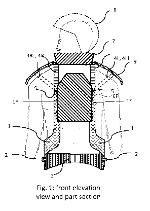
[0019] Fig. 1 illustrates a front elevation view of a soldier wearing a
protective gear of
an embodiment of the invention.
[0020] Fig. 2 illustrates a rear elevation view of a soldier wearing the
protective gear of
the same.
Fig. 3 illustrates a right lateral elevation view of the same.
[0021] Fig. 4 illustrates cross-sections of fore and / or aft vertical
branches (1F, 1B),
one embodiment having an internal channel.
Embodiments of the invention
[0022] The invention will in the following be described and embodiments of the
invention will be explained with reference to the accompanying drawings.
[0023] The invention is a protective armour gear comprising
first, a main belt (3) for attachment around a wearer's hips,
CA 03004699 2018-05-08
WO 2017/086800
PCT/N02016/050228
4
a right and a left side junction (2, 2) on said main belt (3) and arranged
near said
wearer's hip joints,
wherein said junctions (2, 2) holds a right and left side, generally "V" or
"U" shaped fork
structural element (1, 1) by their lower, middle portion (1v, 1v) connected on
said right
and left side junction (2, 2), respectively,
each said fork structural element (1, 1) has a fore vertical branch (1F, 1F)
extending up
along the wearer's frontal chest to an elevation near his right and left
collar bone,
respectively, with a separation of about one half of the wearer's chest width;
opposite to the fore vertical branches, each said fork structural element (1,
1) further
has a rear or back vertical branch (1B, 1B) extending up along the wearer's
back to an
elevation near his right and left shoulder wing, respectively, and having a
separation of
about one half of the wearer's back width,
fourth, there are arranged fore attachment elements (6F, 6F) on said fore
vertical
branches (1F, 1F) for holding a frontal chest armour plate on or between said
fore
vertical branches (F, 1F), and
opposite, on the back, there rear attachment elements (6R, 6R) on said rear or
back
vertical branches (113,1B) for holding a back armour plate on or between said
rear
vertical branches (1B, 1B).
Each fork structural element (1, 1)'5 fore vertical branch (1F, 1F) may extend
from a
common portion of the structural element (1, 1) near its corresponding said
junction (1v,
1v) and extend up along the wearer's frontal chest. A similar structure may
also be
formed with the aft vertical branches. This common portion near the junction
may have a
general downward-pointed triangular shape as shown in Fig 3. The attachment
elements
(6R, 6F) may comprise velcro bands, strings, buttons, or similar attachment
element
types.
[0024] When the front and back chest armour plates are attached on or between
the
upstanding vertical branches, the entire structure is generally continuous
around the
wearer's chest. In the embodiment shown in Figs. 1, 2, and 3, the fork
structural
elements are made with deeply extending armpits formed by the U- or V-
structure of
the fork structural elements.
[0025] In other words, the protective armour gear of the invention may be
described as
a main hip belt (3) holding at its right and left hip-joint near portions,
right and left
junctions (2, 2) for holding a right and left upright two-armed body-
enveloping fork (1,
1) by its lower junction (1v, 1v), the fore and aft branches (1F, 1B) of each
fork
CA 03004699 2018-05-08
WO 2017/086800 PCT/N02016/050228
extending up along the left and right side of the chest and back on either
sides of the
torso, the left and right branches (1F, 1F) on the chest arranged for carrying
a frontal
antiballistic plate, and correspondingly on the back.
[0026] In an embodiment of the invention one or both of the front or rear
antiballistic
plates may be replaced by other gear such as battery packs, radio equipment in
situations wherein one or both of the antiballistic plates are not strictly
required. One
may also replace the rear armour plate with a backpack, which itself may carry
armour.
[0027] In an embodiment of the invention there may be arranged above-shoulder
extending arches. The protective armour gear of the invention in this
embodiment further
comprises a right and a left structural vertical shoulder arch (4R, 4L)
extending from
front to rear above the wearer's shoulders, please see Figs. 1, 2, and 3. The
right and left
structural shoulder arch (4R, 4L) are both connected from an upper portion of
said right
and left fore vertical branch (1F, 1F) and an upper portion of said right and
left rear
vertical branch (18, 18), respectively, and extend above the wearers'
shoulders.
Connection may be through rivets (5) or similar, see Fig. 3. Each structural
shoulder arch
(4R, 4L) is arranged to provide structural support for further armour plates,
such as
shoulder armour plates, helmet, or other equipment. Further, the structural
arches
provide stability to the right and left vertical branches, respectively, and
contribute to a
semi-rigid cage structure about the torso. Please notice that those shoulder
archers (4R,
4L) generally do not load weight from the protective gear onto the shoulders.
The load of
the protective gear, among others the weight of the fore and aft antiballistic
plates, is
generally directed down via the structural fork elements to the main belt on
the hips.
This feature provides some of the core advantages over the prior art.
[0028] In a further embodiment of the invention, the protective armour gear of
the
invention comprises a right and a left structural lateral shoulder arch (4RL,
4LL)
extending angled outward relative to their straight counterparts (4R, 4L), sub
horizontally around the wearer's shoulders. The right and left structural
shoulder arch
(4R, 4L) also connected from an upper portion of said right and left fore
vertical branch
(1F, 1F) and an upper portion of said right and left rear vertical branch (18,
18),
respectively, each structural shoulder arch (4R, 4L) to provide structural
support for
further armour plates, such as shoulder armour plates, or other equipment.
Those
elements may be arranged pivotal so as for allowing elevating the arms in the
lateral
direction, please see Fig. 2. Shoulder shields (9) may be arranged on the
vertical and
lateral shoulder arches. The shoulder shields (9) may be attached pivotal on
the shoulder
CA 03004699 2018-05-08
WO 2017/086800 PCT/N02016/050228
6
archers (4R, 4L) in order to allow elevating the shoulder or upper arm, e.g.
for allowing
aiming, climbing, etc, thus not restricting the mobility of the shoulders.
[0029] Rigid right and left junctions:
In an embodiment of the invention said right and left side junctions (2, 2) on
said main
belt (3) form generally rigid, non-pivoting junctions between said main belt
and said left
and right middle portions (1v, 1v), respectively. Initial tests on the
mobility of the user
indicates that a certain flexibility of the belt as such allows the user to
move relatively
un-restrained even with a non-pivoting junction at the left and right side
near the hip.
[0030] Pivotal junctions
In an embodiment of the invention said right and left side junction (2, 2)
comprise a right
and and a left side pivot axle or link axis (2, 2) extending horizontally out
to the right
and left side, respectively, on said main belt (3), and having said right and
left side,
generally "V" or "U" shaped fork structural element (1, 1) with its lower
middle portion
pivotally connected on said right and left side junction (2, 2). This may
provide even
more mobility than a rigid junction.
[0031] Draped structural elements
In an embodiment of the invention said left and right side "V"- or "U"-shaped
fork
structural elements (1, 1) are each shaped as a bent plate-shaped element with
a
common face of its middle portion (1v, 1v) and its fore and aft vertical
branches (1F, 1B)
draped along the right and left sides of the wearers' torso, respectively. In
an
embodiment of the invention at least said main belt (3), and said right and
left fork
structural elements (1, 1) are arranged in a body-near or tight-fitting
configuration for
being worn near the skin or just above the underwear. This may provide the
smallest and
more stable configuration of the armour gear of the invention. On the other
hand, if the
protective armour gear comprising it s belt and right and left fork structural
elements is
to be worn on over a jacket, the aft vertical branches may carry a backpack
directly,
interchangeable with an antiballistic plate.
[0032] The front and back armour plate usually is made to cover about half the
width of
the chest and back, respectively, as such providing no antiballistic
protection on either
sides of the torso. In an embodiment of the invention said right and left
structural
elements (1, 1) comprise antiballistic armour plates. Further antiballistic
armour may be
attached to the protective armour gear of the invention, such as antiballistic
shoulder
covers indicated in Figs. 1 and 2, neck protective antiballistic cover (7),
etc, according to
CA 03004699 2018-05-08
WO 2017/086800 PCT/N02016/050228
7
the level of threat.
[0033] Composite forks
In an embodiment of the invention said left and right side structural elements
(1, 1) are
made in flexible and bending elastic fibre composite material or thermoplastic
material
such as ABS plastic, PC polycarbonate, PET. In another embodiment of the
invention said
left and right side structural elements (1,1) comprise light metal such panels
or profile
elements of aluminium or titanium. This will ensure light overall weight and
high strength
and durability of the protective gear.
[0034] The right and left structural vertical shoulder arch (4R, 4L) may be
made as
flexible and bending elastic arch-shaped rods of fibre composite material or
thermoplastic
material such as ABS plastic.
[0035] In an embodiment of the invention, one or more of said fore and aft
vertical
branches (1F, 1B) are provided with first internal channel (1FC, 1BC)
extending along its
length, please see Fig. 4. Further, one or more of said right and left
structural vertical
shoulder arch (4R, 4L) may comprise a second internal channel (4RC, 4LC)
connected to
one or more of said first internal channels. Such internal channels reduce the
weight to
strength ratio of the protective gear , but may further provide ventilation
paths through
the channels allowing air to be conducted through the protective gear to air
outlets
(4RCO, 4LCO) to prevent excess heating as such heating may prove a significant
problem
when wearing armour gear and combat equipment. Such ventilation air may be
provided
by a small pump connected to an inlet on the internal channels.