Note : Les descriptions sont présentées dans la langue officielle dans laquelle elles ont été soumises.
' Attorney Docket No.: 38496.396FF01
AUTOMATED DIRECTIONAL STEERING SYSTEMS AND METHODS
FIELD OF THE DISCLOSURE
[0001] The present apparatus, methods, and systems relate generally to
drilling and
particularly to improved automated control of a toolface position of a
drilling apparatus.
BACKGROUND OF THE DISCLOSURE
[0002] Underground drilling involves drilling a borehole through a
formation deep in the
Earth using a drill bit connected to a drill string. Two common drilling
methods, often used
within the same hole, include rotary drilling and slide drilling. Rotary
drilling typically includes
rotating the drilling string, including the drill bit at the end of the drill
string, and driving it
forward through subterranean formations. This rotation often occurs via a top
drive or other
rotary drive equipment at the surface, and as such, the entire drill string
rotates to drive the bit.
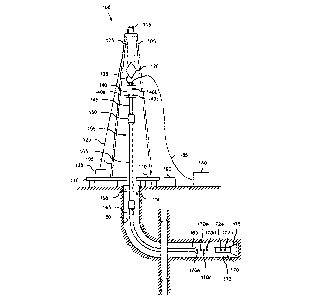
This is often used during straight runs, where the objective is to advance the
bit in a substantially
straight direction through the formation.
[0003] Slide drilling is often used to steer the drill bit to effect a turn
in the drilling path. For
example, slide drilling may employ a drilling motor with a bent housing
incorporated into the
bottom-hole assembly (BHA) of the drill string. During typical slide drilling,
the drill string is
not rotated and the drill bit is rotated exclusively by the drilling motor.
The bent housing steers
the drill bit in the desired direction as the drill string slides through the
bore, thereby effectuating
directional drilling. Alternatively, the steerable system can be operated in a
rotating mode in
which the drill string is rotated while the drilling motor is running.
[0004] Directional drilling can also be accomplished using rotary steerable
systems which
include a drilling motor that forms part of the BHA, as well as some type of
steering device, such
as extendable and retractable arms that apply lateral forces along a borehole
wall to gradually
effect a turn. In contrast to steerable motors, rotary steerable systems
permit directional drilling
to be conducted while the drill string is rotating. As the drill string
rotates, frictional forces are
reduced and more bit weight is typically available for drilling. Hence, a
rotary steerable system
can usually achieve a higher rate of penetration during directional drilling
relative to a steerable
motor, since the combined torque and power of the drill string rotation and
the downhole motor
are applied to the bit.
4851-3947-9140 v 1 - 1 -
CA 3005239 2018-05-17
4r.
4
Attorney Docket No.: 38496.396FF01
[0005] A problem with conventional slide drilling arises when the drill
string is not rotated
because much of the weight on the bit applied at the surface is countered by
the friction of the
drill pipe on the walls of the wellbore. This becomes particularly pronounced
during long
lengths of a horizontally drilled bore hole.
[0006] To reduce wellbore friction during slide drilling, a top drive may
be used to oscillate
or rotationally rock the drill string during slide drilling to reduce drag of
the drill string in the
wellbore. This oscillation can reduce friction in the borehole. However, too
much oscillation
can disrupt the direction of the drill bit and send it off-course during the
slide drilling process,
and too little oscillation can minimize the benefits of the friction
reduction, resulting in low
weight-on-bit and overly slow and inefficient slide drilling.
[0007] The parameters relating to the top-drive oscillation, such as the
number of oscillating
rotations, are typically programmed into the top drive system by an operator,
and may not be
optimal for every drilling situation. For example, the same number of
oscillation revolutions
may be used regardless of whether the drill string is relatively long or
relatively short, and
regardless of the sub-geological structure. Drilling operators, concerned
about turning the bit
off-course during an oscillation procedure, may under-utilize the oscillation
features, limiting its
effectiveness. Because of this, in some instances, an optimal oscillation may
not be achieved,
resulting in relatively less efficient drilling and potentially less bit
progression.
[0008] As such, drilling may be controlled through improved steering
control systems. The
steering control systems may provide steering corrections using reactive
steering that may
provide instructions based on toolface position and proactive steering based
on differential
pressure changes. Such steering corrections may be made by adjusting and/or
offsetting a quill
position of the drilling apparatus. However, under certain conditions,
steering with quill position
offsets may be ineffective under certain drilling conditions. Accordingly,
improved automated
steering control is needed.
SUMMARY OF THE DISCLOSURE
[0009] The present disclosure includes a first aspect that encompasses an
apparatus including
a drilling tool comprising at least one measurement while drilling (MWD)
instrument, a user
interface, and a controller communicatively connected to the drilling tool and
configured to
receive drilling data from the drilling tool, determine that a toolface
orientation of the drilling
4851-3947-9140 v 1 - 2 -
CA 3005239 2018-05-17
4
Attorney Docket No.: 38496.396FF01
tool is outside an advisory sector, record a first oscillation target for the
drilling tool, wherein the
first oscillation target comprises at least a clockwise rotation target and a
counterclockwise
rotation target, determine an updated oscillation target, wherein at least one
of the clockwise
rotation target or counterclockwise rotation target of the updated oscillation
target is different
from the clockwise rotation target or the counterclockwise rotation target of
the first oscillation
target, and provide the updated oscillation target to the drilling tool.
[0010] In a second aspect, the disclosure encompasses a method that
includes receiving
drilling data from a drilling tool, determining that a toolface orientation of
the drilling tool is
outside an advisory sector, recording a first oscillation target for the
drilling tool, wherein the
first oscillation target comprises at least a clockwise rotation target and a
counterclockwise
rotation target, determining an updated oscillation target, wherein at least
one of the clockwise
rotation target or counterclockwise rotation target of the updated oscillation
target is different
from the clockwise rotation target or the counterclockwise rotation target of
the first oscillation
target; and providing the updated oscillation target to the drilling tool.
BRIEF DESCRIPTION OF THE DRAWINGS
[0011] The present disclosure is best understood from the following
detailed description
when read with the accompanying figures. It is emphasized that, in accordance
with the standard
practice in the industry, various features are not drawn to scale. In fact,
the dimensions of the
various features may be arbitrarily increased or reduced for clarity of
discussion.
[0012] FIG. 1 is a schematic of an apparatus according to one or more
aspects of the present
disclosure.
[0013] FIG. 2 is a block diagram schematic of an apparatus according to one
or more aspects
of the present disclosure.
[0014] FIG. 3 is a diagram according to one or more aspects of the present
disclosure.
[0015] FIG. 4 is a flow-chart diagram of at least a portion of a method
according to one or
more aspects of the present disclosure.
[0016] FIG. 5 is a diagram according to one or more aspects of the present
disclosure.
4851-3947-9140 v 1 - 3 -
CA 3005239 2018-05-17
4
' Attorney Docket No.: 38496.396FF01
DETAILED DESCRIPTION
[0017] It is to be understood that the following disclosure provides many
different
embodiments, or examples, for implementing different features of various
embodiments.
Specific examples of components and arrangements are described below to
simplify the present
disclosure. These are, of course, merely examples and are not intended to be
limiting. In
addition, the present disclosure may repeat reference numerals and/or letters
in the various
examples. This repetition is for the purpose of simplicity and clarity and
does not in itself dictate
a relationship between the various embodiments and/or configurations
discussed. Moreover, the
formation of a first feature over or on a second feature in the description
that follows may
include embodiments in which the first and second features are formed in
direct contact, and may
also include embodiments in which additional features may be formed
interposing the first and
second features, such that the first and second features may not be in direct
contact.
[0018] This disclosure provides apparatuses, systems, and methods for
improved drilling
efficiency by evaluating and determining an oscillation regime target, such as
an oscillating
revolution target, for a drilling assembly to reduce wellbore friction on a
drill string while not
disrupting a bit alignment during a slide drilling process. The apparatuses,
systems, and methods
allow a user (alternatively referred to herein as an "operator") or a control
system to determine a
suitable number of revolutions (alternatively referred to as rotations or
wraps) and modify the
number of revolutions to oscillate a tubular string in a manner that improves
the drilling
operation. The term drill string is generally meant to include any tubular
string of one or more
tubulars. This improvement may manifest itself, for example, by increasing the
slide drilling
speed, slide penetration rate, the usable lifetime of components, and/or other
improvements. In
one aspect, the system may modify the oscillation regime target, such as the
target number of
revolutions used in slide drilling based on parameters detected during rotary
drilling. These
parameters may include, for example, one or more of rotary torque, weight on
bit, differential
pressure, hook load, pump pressure, mechanical specific energy (MSE), rotary
RPMs, and tool
face orientation. In addition, the system may modify the oscillation regime
target, such as based
on one or more of the number of revolutions based on technical specifications
of the drilling
equipment, bit type, pipe diameters, vertical or horizontal depth, and other
factors. These may be
used to optimize the rate of penetration or another desired drilling parameter
by maximizing the
number of revolutions, which in turn reduces the wellbore friction along the
drill string for a
4851-3947-9140 v 1 - 4 -
CA 3005239 2018-05-17
' Attorney Docket No.: 38496.396FF01
desired length of the drill string, while in one preferred embodiment not
changing the orientation
of the drill bit toolface during a slide.
[0019] In one aspect, this disclosure is directed to apparatuses, systems,
and methods that
optimize an oscillation regime target, such as the number of revolutions to
provide more
effective drilling. Drilling may be most effective when the drilling system
oscillates the drill
string sufficient to rotate the drill string even very deep within the
borehole, while permitting the
drilling bit to rotate only under the power of the motor. For example, a
revolution setting that
rotates only the upper half of the drill string will be less effective at
reducing drag than a
revolution setting that rotates nearly the entire drill string. Therefore, an
optimal revolution
setting may be one that rotates substantially the entire drill string without
upsetting or rotating
the bottom hole assembly. Further, since excessive oscillating revolutions
during a slide might
rotate the bottom hole assembly and undesirably change the drilling direction,
the optimal
angular setting would not adversely affect the direction of drilling. In
another aspect, this
disclosure is directed to apparatuses, systems, and methods that optimize an
oscillation regime
target, such as a target torque level while oscillating in each direction to
provide more effective
drilling. Therefore, a target torque level may be one that rotates
substantially the entire drill
string without upsetting or rotating the bottom hole assembly. An oscillation
regime target is an
optimal or suitably effective target value of an oscillation parameter. These
may include, for
example, the number of revolutions in each direction during slide drilling,
the level of torque
reached during oscillations during slide drilling, or the level of torque
reached during previous
rotation periods, among others.
[0020] The apparatus and methods disclosed herein may be employed with any
type of
directional drilling system using a rocking technique with an adjustable
target number of
revolutions or an adjustable target torque, including handheld oscillating
drills, casing running
tools, tunnel boring equipment, mining equipment, and oilfield-based equipment
such as those
including top drives. The apparatus is further discussed below in connection
with oilfield-based
equipment, but the oscillation revolution selecting device of this disclosure
may have
applicability to a wide array of fields including those noted above.
[0021] Referring to FIG. 1, illustrated is a schematic view of an apparatus
100 demonstrating
one or more aspects of the present disclosure. The apparatus 100 is or
includes a land-based
drilling rig. However, one or more aspects of the present disclosure are
applicable or readily
4851-3947-9140 v 1 - 5 -
CA 3005239 2018-05-17
' Attorney Docket No.: 38496.396FF01
adaptable to any type of drilling rig, such as jack-up rigs, semisubmersibles,
drill ships, coil
tubing rigs, well service rigs adapted for drilling and/or re-entry
operations, and casing drilling
rigs, among others within the scope of the present disclosure.
[0022] The apparatus 100 includes a mast 105 supporting lifting gear above
a rig floor 110.
The lifting gear includes a crown block 115 and a traveling block 120. The
crown block 115 is
coupled at or near the top of the mast 105, and the traveling block 120 hangs
from the crown
block 115 by a drilling line 125. One end of the drilling line 125 extends
from the lifting gear to
drawworks 130, which is configured to reel out and reel in the drilling line
125 to cause the
traveling block 120 to be lowered and raised relative to the rig floor 110.
The other end of the
drilling line 125, known as a dead line anchor, is anchored to a fixed
position, possibly near the
drawworks 130 or elsewhere on the rig.
[0023] A hook 135 is attached to the bottom of the traveling block 120. A
top drive 140 is
suspended from the hook 135. A quill 145 extending from the top drive 140 is
attached to a saver
sub 150, which is attached to a drill string 155 suspended within a wellbore
160. Alternatively,
the quill 145 may be attached to the drill string 155 directly. It should be
understood that other
conventional techniques for arranging a rig do not require a drilling line,
and these are included
in the scope of this disclosure. In another aspect (not shown), no quill is
present.
[0024] The term "quill" as used herein is not limited to a component which
directly extends
from the top drive, or which is otherwise conventionally referred to as a
quill. For example,
within the scope of the present disclosure, the "quill" may additionally or
alternatively include a
main shaft, a drive shaft, an output shaft, and/or another component which
transfers torque,
position, and/or rotation from the top drive or other rotary driving element
to the drill string, at
least indirectly. Nonetheless, albeit merely for the sake of clarity and
conciseness, these
components may be collectively referred to herein as the "quill."
[0025] As depicted, the drill string 155 typically includes interconnected
sections of drill
pipe 165, a bottom hole assembly (BHA) 170, and a drill bit 175. The BHA 170
may include
stabilizers, drill collars, and/or measurement-while-drilling (MWD) or
wireline conveyed
instruments, among other components. The drill bit 175, which may also be
referred to herein as
a tool, is connected to the bottom of the BHA 170 or is otherwise attached to
the drill string 155.
One or more pumps 180 may deliver drilling fluid to the drill string 155
through a hose or other
conduit 185, which may be fluidically and/or actually connected to the top
drive 140.
4851-3947-9140 v 1 - 6 -
CA 3005239 2018-05-17
' Attorney Docket No.: 38496.396FF01
[0026] The downhole MWD or wireline conveyed instruments may be configured
for the
evaluation of physical properties such as pressure, temperature, torque,
weight-on-bit (WOB),
vibration, inclination, azimuth, toolface orientation in three-dimensional
space, and/or other
downhole parameters. These measurements may be made downhole, stored in solid-
state
memory for some time, and downloaded from the instrument(s) at the surface
and/or transmitted
to the surface. Data transmission methods may include, for example, digitally
encoding data and
transmitting the encoded data to the surface, possibly as pressure pulses in
the drilling fluid or
mud system, acoustic transmission through the drill string 155, electronically
transmitted through
a wireline or wired pipe, and/or transmitted as electromagnetic pulses. MWD
tools and/or other
portions of the BHA 170 may have the ability to store measurements for later
retrieval via
wireline and/or when the BHA 170 is tripped out of the wellbore 160.
[0027] In an exemplary embodiment, the apparatus 100 may also include a
rotating blow-out
preventer (BOP) 158, such as if the well 160 is being drilled utilizing under-
balanced or
managed-pressure drilling methods. In such embodiment, the annulus mud and
cuttings may be
pressurized at the surface, with the actual desired flow and pressure possibly
being controlled by
a choke system, and the fluid and pressure being retained at the well head and
directed down the
flow line to the choke by the rotating BOP 158. The apparatus 100 may also
include a surface
casing annular pressure sensor 159 configured to detect the pressure in the
annulus defined
between, for example, the wellbore 160 (or casing therein) and the drill
string 155.
[0028] In the exemplary embodiment depicted in FIG. 1, the top drive 140 is
used to impart
rotary motion to the drill string 155. However, aspects of the present
disclosure are also
applicable or readily adaptable to implementations utilizing other drive
systems, such as a power
swivel, a rotary table, a coiled tubing unit, a downhole motor, and/or a
conventional rotary rig.
[0029] The apparatus 100 also includes a control system 190 configured to
control or assist
in the control of one or more components of the apparatus 100. For example,
the control system
190 may be configured to transmit operational control signals to the drawworks
130, the top
drive 140, the BHA 170 and/or the pump 180. The control system 190 may be a
stand-alone
component installed near the mast 105 and/or other components of the apparatus
100. In some
embodiments, the control system 190 is physically displaced at a location
separate and apart
from the drilling rig.
4851-3947-9140 v 1 - 7 -
CA 3005239 2018-05-17
Attorney Docket No.: 38496.396FF01
[0030] The control system 190 is also configured to receive electronic
signals via wired or
wireless transmission techniques (also not shown in FIG. 1) from a variety of
sensors and/or
MWD tools included in the apparatus 100, where each sensor is configured to
detect an
operational characteristic or parameter. One such sensor is the surface casing
annular pressure
sensor 159 described above. The apparatus 100 may include a downhole annular
pressure sensor
170a coupled to or otherwise associated with the BHA 170. The downhole annular
pressure
sensor 170a may be configured to detect a pressure value or range in the
annulus-shaped region
defined between the external surface of the BHA 170 and the internal diameter
of the wellbore
160, which may also be referred to as the casing pressure, downhole casing
pressure, MWD
casing pressure, or downhole annular pressure.
[0031] It is noted that the meaning of the word "detecting," in the context
of the present
disclosure, may include detecting, sensing, measuring, calculating, and/or
otherwise obtaining
data. Similarly, the meaning of the word "detect" in the context of the
present disclosure may
include detect, sense, measure, calculate, and/or otherwise obtain data.
[0032] The apparatus 100 may additionally or alternatively include a
shock/vibration sensor
170b that is configured for detecting shock and/or vibration in the BHA 170.
The apparatus 100
may additionally or alternatively include a mud motor delta pressure (AP)
sensor 172a that is
configured to detect a pressure differential value or range across one or more
motors 172 of the
BHA 170. The one or more motors 172 may each be or include a positive
displacement drilling
motor that uses hydraulic power of the drilling fluid to drive the bit 175,
also known as a mud
motor. One or more torque sensors 172b may also be included in the BHA 170 for
sending data
to the control system 190 that is indicative of the torque applied to the bit
175 by the one or more
motors 172.
[0033] The apparatus 100 may additionally or alternatively include a
toolface sensor 170c
configured to detect the current toolface orientation. The toolface sensor
170c may be or include
a conventional or future-developed "magnetic toolface" which detects toolface
orientation
relative to magnetic north or true north. Alternatively, or additionally, the
toolface sensor 170c
may be or include a conventional or future-developed "gravity toolface" which
detects toolface
orientation relative to the Earth's gravitational field. The toolface sensor
170c may also, or
alternatively, be or include a conventional or future-developed gyro sensor.
The apparatus 100
4851-3947-9140 v 1 - 8 -
CA 3005239 2018-05-17
' Attorney Docket No.: 38496.396FF01
may additionally or alternatively include a WOB sensor 170d integral to the
BHA 170 and
configured to detect WOB at or near the BHA 170.
[0034] The apparatus 100 may additionally or alternatively include a torque
sensor 140a
coupled to or otherwise associated with the top drive 140. The torque sensor
140a may
alternatively be located in or associated with the BHA 170. The torque sensor
140a may be
configured to detect a value or range of the torsion of the quill 145 and/or
the drill string 155
(e.g., in response to operational forces acting on the drill string). The top
drive 140 may
additionally or alternatively include or otherwise be associated with a speed
sensor 140b
configured to detect a value or range of the rotational speed of the quill
145.
[0035] The top drive 140, draw works 130, crown or traveling block,
drilling line or dead
line anchor may additionally or alternatively include or otherwise be
associated with a WOB
sensor 140c (e.g., one or more sensors installed somewhere in the load path
mechanisms to
detect WOB, which can vary from rig-to-rig) different from the WOB sensor
170d. The WOB
sensor 140c may be configured to detect a WOB value or range, where such
detection may be
performed at the top drive 140, draw works 130, or other component of the
apparatus 100.
[0036] The detection performed by the sensors described herein may be
performed once,
continuously, periodically, and/or at random intervals. The detection may be
manually triggered
by an operator or other person accessing a human-machine interface (HMI), or
automatically
triggered by, for example, a triggering characteristic or parameter satisfying
a predetermined
condition (e.g., expiration of a time period, drilling progress reaching a
predetermined depth,
drill bit usage reaching a predetermined amount, etc.). Such sensors and/or
other detection
equipment may include one or more interfaces which may be local at the
well/fig site or located
at another, remote location with a network link to the system.
[0037] FIG. 2 illustrates a block diagram of a portion of an apparatus 200
according to one or
more aspects of the present disclosure. FIG. 2 shows the control system 190,
the BHA 170, and
the top drive 140, identified as a drive system. The apparatus 200 may be
implemented within
the environment and/or the apparatus shown in FIG. 1.
[0038] The control system 190 includes a user-interface 205 and a
controller 210.
Depending on the embodiment, these may be discrete components that are
interconnected via
wired or wireless technique. Alternatively, the user-interface 205 and the
controller 210 may be
integral components of a single system.
4851-3947-9140 v 1 - 9 -
CA 3005239 2018-05-17
Attorney Docket No.: 38496.396FF01
[0039] The user-interface 205 may include an input mechanism 215 permitting
a user to
input a left oscillation revolution setting and a right oscillation revolution
setting. These settings
control the number of revolutions of the drill string as the system controls
the top drive (or other
drive system) to oscillate a portion of the drill string from the top. In some
embodiments, the
input mechanism 215 may be used to input additional drilling settings or
parameters, such as
acceleration, toolface set points, rotation settings, and other set points or
input data, including a
torque target value, such as a previously calculated torque target value, that
may determine the
limits of oscillation. A user may input information relating to the drilling
parameters of the drill
string, such as BHA information or arrangement, drill pipe size, bit type,
depth, formation
information. The input mechanism 215 may include a keypad, voice-recognition
apparatus, dial,
button, switch, slide selector, toggle, joystick, mouse, data base and/or any
other data input
device available at any time to one of ordinary skill in the art. Such an
input mechanism 215 may
support data input from local and/or remote locations. Alternatively, or
additionally, the input
mechanism 215, when included, may permit user-selection of predetermined
profiles, algorithms,
set point values or ranges, such as via one or more drop-down menus. The data
may also or
alternatively be selected by the controller 210 via the execution of one or
more database look-up
procedures. In general, the input mechanism 215 and/or other components within
the scope of
the present disclosure support operation and/or monitoring from stations on
the rig site as well as
one or more remote locations with a communications link to the system,
network, local area
network (LAN), wide area network (WAN), Internet, satellite-link, and/or
radio, among other
techniques or systems available to those of ordinary skill in the art.
[0040] The user-interface 205 may also include a display 220 for visually
presenting
information to the user in textual, graphic, or video form. The display 220
may also be utilized
by the user to input drilling parameters, limits, or set point data in
conjunction with the input
mechanism 215. For example, the input mechanism 215 may be integral to or
otherwise
communicably coupled with the display 220.
[0041] In one example, the controller 210 may include a plurality of pre-
stored selectable
oscillation profiles that may be used to control the top drive or other drive
system. The pre-
stored selectable profiles may include a right rotational revolution value and
a left rotational
revolution value. The profile may include, in one example, 5.0 rotations to
the right and -3.3
rotations to the left. These values are preferably measured from a central or
neutral rotation.
4851-3947-9140 v 1 - 10 -
CA 3005239 2018-05-17
Attorney Docket No.: 38496.396FF01
[0042] In addition to having a plurality of oscillation profiles, the
controller 210 includes a
memory with instructions for performing a process to select the profile. In
some embodiments,
the profile is a simply one of either a right (i.e., clockwise) revolution
setting and a left (i.e.,
counterclockwise) revolution setting. Accordingly, the controller 210 may
include instructions
and capability to select a pre-established profile including, for example, a
right rotation value and
a left rotation value. Because some rotational values may be more effective
than others in
particular drilling scenarios, the controller 210 may be arranged to identify
the rotational values
that provide a suitable level, and preferably an optimal level, of drilling
speed. The controller
210 may be arranged to receive data or information from the user, the bottom
hole assembly 170,
and/or the top drive 140 and process the information to select an oscillation
profile that might
enable effective and efficient drilling.
[0043] The BHA 170 may include one or more sensors, typically a plurality
of sensors,
located and configured about the BHA to detect parameters relating to the
drilling environment,
the BHA condition and orientation, and other information. In the embodiment
shown in FIG. 2,
the BHA 170 includes an MWD casing pressure sensor 230 that is configured to
detect an
annular pressure value or range at or near the MWD portion of the BHA 170. The
casing
pressure data detected via the MWD casing pressure sensor 230 may be sent via
electronic signal
to the controller 210 via wired or wireless transmission.
[0044] The BHA 170 may also include an MWD shock/vibration sensor 235 that
is
configured to detect shock and/or vibration in the MWD portion of the BHA 170.
The
shock/vibration data detected via the MWD shock/vibration sensor 235 may be
sent via
electronic signal to the controller 210 via wired or wireless transmission.
[0045] The BHA 170 may also include a mud motor AP sensor 240 that is
configured to
detect a pressure differential value or range across the mud motor of the BHA
170. The pressure
differential data detected via the mud motor AP sensor 240 may be sent via
electronic signal to
the controller 210 via wired or wireless transmission. The mud motor AP may be
alternatively or
additionally calculated, detected, or otherwise determined at the surface,
such as by calculating
the difference between the surface standpipe pressure just off-bottom and
pressure once the bit
touches bottom and starts drilling and experiencing torque.
[0046] The BHA 170 may also include a magnetic toolface sensor 245 and a
gravity toolface
sensor 250 that are cooperatively configured to detect the current toolface.
The magnetic toolface
4851-3947-9140 vi - 11 -
CA 3005239 2018-05-17
' Attorney Docket No.: 38496.396FF01
sensor 245 may be or include a conventional or future-developed magnetic
toolface sensor which
detects toolface orientation relative to magnetic north or true north. The
gravity toolface sensor
250 may be or include a conventional or future-developed gravity toolface
sensor which detects
toolface orientation relative to the Earth's gravitational field. In an
exemplary embodiment, the
magnetic toolface sensor 245 may detect the current toolface when the end of
the wellbore is less
than about 7 from vertical, and the gravity toolface sensor 250 may detect
the current toolface
when the end of the wellbore is greater than about 7 from vertical. However,
other toolface
sensors may also be utilized within the scope of the present disclosure that
may be more or less
precise or have the same degree of precision, including non-magnetic toolface
sensors and non-
gravitational inclination sensors. In any case, the toolface orientation
detected via the one or
more toolface sensors (e.g., sensors 245 and/or 250) may be sent via
electronic signal to the
controller 210 via wired or wireless transmission.
[0047] The BHA 170 may also include an MWD torque sensor 255 that is
configured to
detect a value or range of values for torque applied to the bit by the
motor(s) of the BHA 170.
The torque data detected via the MWD torque sensor 255 may be sent via
electronic signal to the
controller 210 via wired or wireless transmission.
[0048] The BHA 170 may also include an MWD weight-on-bit (WOB) sensor 260
that is
configured to detect a value or range of values for WOB at or near the BHA
170. The WOB data
detected via the MWD WOB sensor 260 may be sent to the controller 210 via one
or more
signals, such as one or more electronic signals (e.g., wired or wireless
transmission) or mud
pulse telemetry, or any combination thereof.
[0049] The top drive 140 may also or alternatively include one or more
sensors or detectors
that provide information that may be considered by the controller 210 when it
selects the
oscillation profile. In this embodiment, the top drive 140 includes a rotary
torque sensor 265 that
is configured to detect a value or range of the reactive torsion of the quill
145 or drill string 155.
The top drive 140 also includes a quill position sensor 270 that is configured
to detect a value or
range of the rotational position of the quill, such as relative to true north
or another stationary
reference. The rotary torque and quill position data detected via sensors 265
and 270,
respectively, may be sent via electronic signal to the controller 210 via
wired or wireless
transmission.
4851-3947-9140 v 1 - 12 -
CA 3005239 2018-05-17
' Attorney Docket No.: 38496.396FF01
[0050] The top drive 140 may also include a hook load sensor 275, a pump
pressure sensor
or gauge 280, a mechanical specific energy (MSE) sensor 285, and a rotary RPM
sensor 290.
[0051] The hook load sensor 275 detects the load on the hook 135 as it
suspends the top
drive 140 and the drill string 155. The hook load detected via the hook load
sensor 275 may be
sent via electronic signal to the controller 210 via wired or wireless
transmission.
[0052] The pump pressure sensor or gauge 280 is configured to detect the
pressure of the
pump providing mud or otherwise powering the BHA from the surface. The pump
pressure
detected by the pump sensor pressure or gauge 280 may be sent via electronic
signal to the
controller 210 via wired or wireless transmission.
[0053] The mechanical specific energy (MSE) sensor 285 is configured to
detect the MSE
representing the amount of energy required per unit volume of drilled rock. In
some
embodiments, the MSE is not directly sensed, but is calculated based on sensed
data at the
controller 210 or other controller about the apparatus 100.
[0054] The rotary RPM sensor 290 is configured to detect the rotary RPM of
the drill string.
This may be measured at the top drive or elsewhere, such as at surface portion
of the drill string.
The RPM detected by the RPM sensor 290 may be sent via electronic signal to
the controller 210
via wired or wireless transmission.
[0055] In FIG. 2, the top drive 140 also includes a controller 295 and/or
other device for
controlling the rotational position, speed and direction of the quill 145 or
other drill string
component coupled to the top drive 140 (such as the quill 145 shown in FIG.
1). Depending on
the embodiment, the controller 295 may be integral with or may form a part of
the controller
210.
[0056] The controller 210 is configured to receive detected information
(i.e., measured or
calculated) from the user-interface 205, the BHA 170, and/or the top drive
140, and utilize such
information to continuously, periodically, or otherwise operate to determine
and identify an
oscillation regime target, such as a target rotation parameter having improved
effectiveness. The
controller 210 may be further configured to generate a control signal, such as
via intelligent
adaptive control, and provide the control signal to the top drive 140 to
adjust and/or maintain the
oscillation profile to most effectively perform a drilling operation.
[0057] Moreover, as in the exemplary embodiment depicted in FIG. 2, the
controller 295 of
the top drive 140 may be configured to generate and transmit a signal to the
controller 210.
4851-3947-9140 v 1 - 13 -
CA 3005239 2018-05-17
Attorney Docket No.: 38496.396FF01
Consequently, the controller 295 of the top drive 140 may be configured to
modify the number
of rotations in an oscillation, the torque level threshold, or other
oscillation regime target. It
should be understood the number of rotations used at any point in the present
disclosure may be
a whole or fractional number.
[0058] FIG. 3 shows a portion of the display 220 that conveys information
relating to the
drilling process, the drilling rig apparatus 100, the top drive 140, and/or
the BHA 170 to a user,
such as a rig operator. As can be seen, the display 220 includes a right
oscillation amount at 222,
shown in this example as 5.0, and a left oscillation amount at 224, shown in
this example as -3Ø
These values represent the number of revolutions in each direction from a
neutral center when
oscillating. In a preferred embodiment, the oscillation revolution values are
selected to be values
that provide a high level of oscillation so that a high percentage of the
drill string oscillates, to
reduce axial friction on the drill string from the bore wall, while not
disrupting the direction of
the BHA. In certain embodiments, the right and left oscillation amounts may be
determined
based on rotational torque (e.g., previously calculated rotational torque).
[0059] In this example, the display 220 also conveys information relating
to the actual
torque. Here, right torque and left torque may be entered in the regions
identified by numerals
226 and 228 respectively.
[0060] In addition to showing the oscillation rotational or revolution
values and oscillation
torque, the display 220 also includes a dial or target shape having a
plurality of concentric nested
rings. In this embodiment, the magnetic-based tool face orientation data is
represented by the
line 298 and the data 232, and the gravity-based tool face orientation data is
represented by
symbols 234 and the data 236. The symbols and information may also or
alternatively be
distinguished from one another via color, size, flashing, flashing rate,
shape, and/or other graphic
indicator or technique.
[0061] In the exemplary display 220 shown in FIG. 3, the display 220
includes a historical
representation of the tool face measurements, such that the most recent
measurement and a
plurality of immediately prior measurements are displayed. However, in other
embodiments, the
symbols may indicate only the most recent tool face and quill position
measurements.
[0062] The display 220 may also include a textual and/or other type of
indicator 248
displaying the current or most recent inclination of the remote end of the
drill string. The display
220 may also include a textual and/or other type of indicator 250 displaying
the current or most
4851-3947-9140 v 1 - 14 -
CA 3005239 2018-05-17
= Attorney Docket No.: 38496.396FF01
recent azimuth orientation of the remote end of the drill string. Additional
selectable buttons,
icons, and information may be presented to the user as indicated in the
exemplary display 220.
Additional details that may be included include those disclosed in U.S. Patent
No. 8,528,663 to
Boone, which is incorporated herein by express reference thereto.
[0063] FIG. 4 is a flow chart showing an exemplary method for automated
steering of an
oscillation regime while slide drilling. The method illustrated in FIG. 4 may
be used to, at least,
automatically adjust the right and left oscillation rotational or revolution
values (e.g., by one or
more of the controllers described herein) to provide faster toolface
manipulation and improved
control while drilling (e.g., while directional drilling).
[0064] The method illustrated in FIG. 4 may commence at step 402. In step
402, user inputs
directed towards one or more operating parameters are received. Such
parameters may include,
for example, one or more rotational or revolution values (e.g., right and left
oscillation rotational
or revolution values), a target toolface orientation, toolface based
correction conditions, or other
parameters that may be controlled or determined through user inputs. Toolface
based correction
conditions may be conditions that, when met, result in the one or more
controllers providing
updated instructions to one or more components of the apparatus 100 or
conditions and/or
thresholds for determining that such conditions are met. Such counters or
thresholds may
include, for example, a maximum toolface correction count, a toolface
correction count, an
oscillation target update count, a number of toolface cycles to wait, and/or
other such counters or
thresholds that may be described in further detail herein.
[0065] After step 402, the method may proceed to step 404. In step 404, the
toolface
orientation may be compared to a toolface advisory. The toolface advisory may
be a
recommended toolface orientation. In certain embodiments, the toolface
advisory may be an
orientation range (e.g., any toolface orientation within the orientation range
may be within the
toolface advisory). As such, the toolface advisory may be, for example, a
preferred angular zone
or toolface orientation that the driller or automated drilling program may aim
to keep the toolface
orientation or toolface readings within. In certain embodiments, the toolface
advisory may be a
range of orientations around a single value target toolface orientation. In
other embodiments, the
target toolface orientation may be a range of angles and the toolface advisory
may be such a
range. In yet another embodiment, the target toolface orientation may be a
range of angles and
the toolface advisory may be a range of orientations around the range.
4851-3947-9140 v 1 - 15 -
CA 3005239 2018-05-17
Attorney Docket No.: 38496.396FF01
[0066] If the toolface orientation is within the toolface advisory, the
method may return to
step 402 and receive additional user inputs and/or may continue to monitor the
toolface readings.
If the toolface orientation is outside the toolface advisory, the method may
proceed to step 406.
In step 406, the toolface orientation may be checked to determine if the
toolface orientation is
within a threshold deviation. The threshold deviation may be a single
deviation value and/or a
range of values. In certain embodiments, the threshold deviation may be
determined and/or
determined in step 402. For example, the threshold deviation of certain
embodiments may be a
deviation of between 25 to 75 degrees (e.g., 50 degrees) from the target
toolface orientation. The
threshold deviation may be an orientation or orientations around the toolface
advisory (e.g.,
around one or both sides of the toolface advisory) and greater than the
toolface advisory.
[0067] If the toolface orientation in step 406 is within the threshold
deviation, the method
may proceed to step 408. Otherwise, the method may proceed to step 416.
[0068] In step 408, the one or more controllers may determine if one or
more toolface based
correction conditions are met. In certain embodiments, toolface orientation
data may be
periodically communicated to the one or more controllers through one or more
data cycles and
the one or more controllers may determine the toolface orientation from such
data. The toolface
based correction conditions may include, for example, determining whether a
sufficient number
of data cycles indicating that the toolface orientation is outside the
toolface advisory, but within
the threshold deviation, has been received. In certain embodiments, the
toolface based correction
condition may determine that a sufficient number of data cycles indicating
that the toolface
orientation is outside the advisory has been received in a row (e.g., that the
last two or more such
data cycles received both or all indicate that the toolface orientation is
outside the toolface
advisory). The number of data cycles may be tracked by, for example, a data
cycle counter
within the one or more controllers and the data cycle counter may be compared
to the number of
data cycles (received continuously or a number of which is received within a
total number of
cycles, such as four within the last five cycles) received indicating that the
toolface orientation is
outside the toolface advisory.
[0069] If the toolface based correction conditions are met, the method may
proceed to step
410. In step 410, a toolface based correction may be communicated by the one
or more
controllers. The toolface based correction may be, for example, any correction
that does not
change settings related to operating the drill string 155. As such, the
toolface based correction
4851-3947-9140 v 1 - 16 -
CA 3005239 2018-05-17
Attorney Docket No.: 38496.396FF01
may include changes to one or more instructions for operating the drill pipe
165, the BHA 170,
and/or other components of the apparatus 100. Additionally, in certain
examples, the toolface
correction counter may be incremented to indicate that an additional toolface
based correction
has been performed.
[0070] The method may then move to step 412. In step 412, the toolface
correction counter
may be compared to a maximum toolface correction count. If the toolface
correction counter is
equal to the maximum toolface correction count, the toolface correction
counter may be reset in
step 414 (e.g., zeroed) and then the method may proceed to step 416.
Otherwise, the method
may revert back to step 404 to check whether the toolface orientation is
within the toolface
advisory.
[0071] In step 416, the current oscillation targets may be recorded and/or
stored. The
oscillation targets may include parameters associated with the operation of
the drill string 155
such as, for example, one or more rotational or revolution values (e.g., right
and left oscillation
rotational or revolution values) or other parameters. The current oscillation
targets may be
recorded and/or stored within a memory of the one or more controllers.
[0072] After step 416, the method may proceed to step 418. In step 418, the
oscillation
targets may be changed. Changing the oscillation targets may include changing
one or more of
the rotational or revolution values (e.g., right and left oscillation
rotational or revolution values)
or other parameters related to operation of the drill string 155. As an
illustrative example, the
target rotational or revolution values may be changed by 0.25-1.75 revolutions
towards the target
toolface orientation. As such, an additional 0.5 revolutions or wraps towards
the target toolface
orientation may be added to the target rotational or revolution value. In
certain embodiments, a
direction of change (e.g., whether the right or left rotational or revolution
values are changed)
may be determined. Such a direction of change may be a change that may be
determined to help
change the toolface orientation towards the target toolface orientation. For
example, the target
rotational or revolution values may be increased by, e.g., 0.5 revolutions
using the shortest
distance towards the target direction as the determining factor (e.g., would
follow the 180 degree
rule). As such, if the toolface is 150 degrees left of the target toolface
and, thus, 210 degrees
right of the target toolface, the oscillation to the left of the toolface
would be increased towards
the target.
4851-3947.9140v1 - 17 -
CA 3005239 2018-05-17
Attorney Docket No.: 38496.396FF01
[0073] The method may then proceed to step 420. In step 420, the one or
more controllers
may determine if the toolface orientation is within the toolface advisory or
within the threshold
deviation. The one or more controllers may make such a determination after a
set number of
toolface cycles has passed since the previous step of the method (e.g., in
certain embodiments,
the previous step may be one of steps 418, 426, or 428). The set number of
toolface cycles in
step 420 may be entered by a user in step 402 or determined in another manner.
[0074] If the toolface orientation is within the toolface advisory or
within the threshold
deviation, the method may proceed to step 422. If the toolface orientation is
not within the
toolface advisory or not within the threshold deviation, the method may
proceed to step 424.
[0075] In step 422, upon determining that the toolface orientation is
within the toolface
advisory or within the threshold deviation, the oscillation targets recorded
and/or stored in step
416 may be restored (e.g., re-communicated from the one or more controllers to
the drill string
155 or components controlling the drill string 155). As such, the drill string
155 may again be
driven with settings that include the oscillation targets stored in step 416.
The method may then
return to step 404.
[0076] In step 424, an oscillation target update count may be compared to
an update target
count. The oscillation target update count may be a count indicating the
number of times that the
oscillation targets have been changed. In some embodiments, the oscillation
target update count
may track oscillation target changes performed in one or more of steps 418,
426, and 428. The
update target count may be entered by a user in step 402 and may be a
threshold count that the
update count is compared against. Certain embodiments of the method may allow
for the update
target count to be changed while the method is performed. If the oscillation
target update count
is equal to the update target count, the method may proceed to step 426. If
the oscillation target
update count is less than the update target count, the method may proceed to
step 428. If the
oscillation target update count is greater than the update target count, the
method may proceed to
step 430.
[0077] In step 426, the oscillation target may be changed and the
oscillation target update
count may be incremented. The oscillation target may be changed so that the
target rotational or
revolution values may be changed by removing 0.25-2.0 revolutions or wraps
(e.g., 1.0
revolutions or wraps) from a direction opposite that of the target toolface
orientation. The
method may then return to step 420.
4851-3947-9140 v 1 - 18 -
CA 3005239 2018-05-17
Attorney Docket No.: 38496.396FF01
[0078] In step 428, the oscillation target may be changed and the
oscillation target update
count may be incremented. The oscillation target change in step 428 may be
different than the
oscillation target change in step 426. In certain embodiments, before the
oscillation target is
changed in step 428, the one or more controllers may determine if change
conditions are met.
The change conditions may include, for example, if the toolface orientation
deviates from the
target toolface orientation by greater than a threshold amount (e.g., deviates
by 30 degrees or
more, such as 50 degrees) and/or that the oscillation target change performed
in step 418 has
resulted in a toolface orientation change greater than, equal to, or less than
a threshold change
amount (e.g., the oscillation target change performed in step 418 has changed
the toolface
orientation by less than 30 degrees towards the target toolface orientation).
[0079] If the change conditions are met, the oscillation target may be
changed. In certain
examples, the oscillation target may be changed by adding 0.25-1.75
revolutions (e.g., 0.5
revolutions or wraps) towards the target toolface orientation. The method may
then return to
step 420.
[0080] In step 430, the display 220 and/or another such user interface
(e.g., an interface that
may communicate with visual, audible, haptic, and/or message formats) may
alert the driller for
a decision as to whether to continue drilling. If the driller provides a
response indicating that
drilling will cease, the method may proceed to step 434 and drilling may be
stopped. If the
driller provides a response indicating that drilling will continue, the method
may proceed to step
432. In step 432, the update target count may be reset (e.g., zeroed) and then
the method may
proceed to step 428.
[0081] Accordingly, the method may illustrate a technique for automated
steering to
manipulate toolface position. The method described herein may be automatically
performed by
one or more controllers of the apparatus 100 and may allow for faster toolface
manipulation as
compared to, for example, manua1 operation by a driller. Additionally, the
method described
herein may allow for improved control that may allow for drilling more closely
conforms to the
target toolface orientation.
[0082] FIG. 5 is an exemplary graph 500 showing the representative drilling
resistance
function 502 during a rotary drilling period. This information is used to
determine a
recommended oscillation revolution value for both the right and left rotations
during a slide
drilling procedure that follows. Referring to Fig. 5, the graph 500 includes a
drilling resistance
4851-3947-9140 v 1 - 19 -
CA 3005239 2018-05-17
Attorney Docket No.: 38496.396FF01
function 502 along the y-axis representing the calculated representative
value. The x-axis
represents time including a rotary drilling segment or period followed
immediately thereafter by
a slide drilling segment or period.
[0083] The exemplary chart of FIG. 5 shows the drilling resistance function
over time during
the rotary drilling segment. In this example, the drilling resistance function
is relatively stable
during the rotary drilling segment. As indicated above, the rotary drilling
segment may be a
period of time immediately prior to a slide and may be any period of time, and
may be, for
example, an amount of time in the range of about 20 minutes to about 90
minutes. It also may be
the time taken to accomplish a task, such as to advance a stand. The
controller 210 may process
and output the drilling resistance function in real-time during drilling so as
to have a real-time
output. In other examples, the data from all sensors is saved and averaged,
and the controller
may then provide a single drilling resistance function for a time period of
the rotary drilling
segment.
[0084] In this chart in FIG. 5, the controller 210 assigns an average value
to the drilling
resistance function over the designated time period, which in this example,
for explanation only,
is shown as 100%.
[0085] In certain embodiments, the controller 210 may, after processing the
received
information to generate a drilling resistance function, output a new
oscillation revolution value
based on the received feedback data. For example, based on the drilling
resistance function
shown in Fig. 5, the controller 210 may be configured to output a recommended
number of right
oscillation revolutions and a number of left oscillation revolutions. The
right and left oscillation
revolution numbers may be selected to be revolution values that provide
rotation to a relatively
high percentage of the drill pipe while not disrupting the direction of the
BHA. Because of this,
frictional resistance is minimized, while maintaining a low risk or no risk of
moving the BHA off
course during the slide drilling. To make this selection, the controller 210
may include a table
that provides an oscillation revolution value based solely on the drilling
resistance function. In
some embodiments, the controller 210 may include multiple tables that
correspond to the drilling
resistance function and additional factors.
[0086] In some embodiments, the controller 210 outputs the oscillation
revolution values to
the user-interface 205, and the values on the display, such as the display 220
in FIG. 3, are
automatically updated. In other embodiments, the controller 210 makes
recommendations to the
4851-3947-9140 v 1 - 20 -
CA 3005239 2018-05-17
Attorney Docket No.: 38496.396FF01
operator through the display 220 or other elements of the user-interface 205.
When
recommendations are made, the operator may choose to accept or decline the
recommendations
or may make other adjustments, for example, to move the oscillation revolution
values closer to
the recommended values. In the examples shown, the oscillation revolution
values may be, for
example, and without limitation, in the range of 0-35 revolutions to the right
and 0-17
revolutions to the left. Other ranges and values are contemplated. In some
examples, the
recommended right and left oscillation values are different (or asymmetric),
while in others they
are the same (or symmetric). By operating at the recommended oscillation
revolution values, the
slide drilling procedure may be made more efficient by reducing the amount of
friction on the
drill string while still having low risk of moving the BHA off course.
[0087] For explanation only, the slide drilling segment is shown in FIG. 5
immediately
following the rotary drilling segment. Here, the recommended oscillation
revolution values are
such that the drilling resistance function, measured during the slide drilling
segment, has a target
peak range of about 70% to 80% of the average drilling resistance function
taken during the
rotary drilling segment time period immediately preceding the slide drilling
segment. For
example, a target range of about 10.2 oscillation revolutions to the right and
7.9 oscillation
revolutions to the left may provide a peak drilling resistance function in a
desired range. In FIG.
5, the right and left oscillations appear as spikes in the drilling resistance
function during the
time period of the slide drilling segment. In other instances, the target peak
range is about 80%
of the average drilling resistance function taken during the rotary drilling
segment and in yet
others, the target range is greater than about 50% of the average drilling
resistance function taken
during the rotary drilling segment.
[0088] In some embodiments, the drilling resistance function is monitored
during a slide
drilling procedure. It may also be taken into account, along with the drilling
resistance function,
to determine the recommended oscillation revolution values for a subsequent
slide drilling
procedure. For example, with reference to FIG. 5, the slide drilling segment
may be monitored
and compared to a threshold determined by the controller. In this example, the
threshold is 80%
of the average drilling resistance function during the rotary drilling
segment. Depending on the
embodiment, the 80% threshold may be a ceiling, may be a floor, or may be a
target range for the
drilling resistance function during the slide drilling segment. By monitoring
the drilling
resistance function during a slide drilling procedure, the controller 210 may
recommend
4851-3947-9140 v 1 - 21 -
CA 3005239 2018-05-17
Attorney Docket No.: 38496.396FF01
oscillation values taking into account all available information. Accordingly,
as the BHA
proceeds through different subterranean formations, the system may respond by
modifying or
adapting the approach to address increases or decreases in wellbore resistance
for each slide.
[0089] While the above method is described to automatically determine a
target range of
rotational oscillation, the systems and methods described herein also
contemplate using the
drilling resistance function to determine a target range, threshold, ceiling
or floor for any
oscillation regime target, including a torque limit used to control the amount
of oscillation.
Accordingly, the description herein applies equally to other oscillation
regimes. For example, it
can determine a target torque to be achieved when rotating right and a target
torque to be
achieved when rotating left. This target may then be input into the controller
to provide a more
effective operation to increase the effectiveness of slide drilling.
[0090] By using the systems and method described herein, a rig operator can
more easily
operate the rig during slide drilling at a maximum efficiency to save time and
reduce drilling
costs.
[0091] In view of all of the above and the figures, one of ordinary skill
in the art will readily
recognize that the present disclosure introduces an apparatus that may include
a drilling tool
comprising at least one measurement while drilling instrument, a user
interface, and a controller
communicatively connected to the drilling tool and configured to receive
drilling data from the
drilling tool, determine that a toolface orientation of the drilling tool is
outside an advisory
sector, record a first oscillation target for the drilling tool, wherein the
first oscillation target
comprises at least a clockwise rotation target and a counterclockwise rotation
target, determine
an updated oscillation target, where at least one of the clockwise rotation
target or
counterclockwise rotation target of the updated oscillation target is
different from the clockwise
rotation target or the counterclockwise rotation target of the first
oscillation target, and provide
the updated oscillation target to the drilling tool.
[0092] In an aspect of the invention, the controller may be further
configured to determine,
from at least the drilling data, that the toolface orientation of the drilling
tool is greater than a
threshold deviation from a target toolface orientation, where the recording
the first oscillation
target and the determining the updated oscillation target is responsive to
determining that the
toolface orientation is greater than the threshold deviation.
4851-3947-9140 v 1 - 22 -
CA 3005239 2018-05-17
= Attorney Docket No.: 38496.396FF01
[0093] In another aspect of the invention, the controller may be further
configured to
determine, from at least the drilling data, that the toolface orientation of
the drilling tool is less
than a threshold deviation from a target toolface orientation, provide a
toolface based correction
to the drilling tool, and increment a toolface correction counter responsive
to providing the
toolface based correction. In certain such aspects, the controller may be
further configured to
determine that the toolface correction counter is equal to or greater than a
maximum toolface
correction count, where the recording the first oscillation target and the
determining the updated
oscillation target is responsive to determining that the toolface correction
counter is equal to or
greater than the maximum toolface correction count.
[0094] In another aspect of the invention, determining the updated
oscillation target includes
determining a direction of change. In certain such aspects, determining the
updated oscillation
target includes changing the clockwise rotation target and/or the
counterclockwise rotation target
by 0.25-1.75 revolutions in the direction of change.
[0095] In another aspect of the invention, the controller may be further
configured to
determine, from at least the drilling data, that an updated toolface
orientation of the drilling tool
is less than a threshold deviation from a target toolface orientation and/or
that the toolface
orientation of the drilling tool is within the advisory sector, and provide
the first oscillation target
to the drilling tool. In certain such aspects, at least the determining the
updated toolface
orientation is performed after a preset number of toolface cycles.
[0096] In another aspect of the invention, the controller may be further
configured to
determine, from at least the drilling data, that an updated toolface
orientation of the drilling tool
is greater than a threshold deviation from a target toolface orientation and
that the toolface
orientation of the drilling tool is outside the advisory sector, and determine
an oscillation target
update count. In certain such aspects, the controller may be further
configured to determine that
the oscillation target update count is less than an update target count,
determine that the toolface
orientation of the drilling tool is greater than the threshold deviation and
that the toolface
orientation changed less than 30 degrees responsive to the updated oscillation
target, determine a
further updated oscillation target, wherein at least one of the clockwise
rotation target or
counterclockwise rotation target of the further updated oscillation target is
different, and increase
the oscillation target update count. In certain additional aspects, the
controller may be further
configured to determine that the oscillation target update count is equal to
an update target count,
4851-3947-9140 v 1 - 23 -
CA 3005239 2018-05-17
= = Attorney Docket No.: 38496.396FF01
determine a further updated oscillation target, wherein at least one of the
clockwise rotation
target or counterclockwise rotation target of the further updated oscillation
target is different, and
increase the oscillation target update count. In another such aspect, the
controller may be further
configured to determine that the oscillation target update count is greater
than an update target
count, and communicate a continue slide request via the user interface.
[0097] In another aspect of the invention, a method may be introduced that
may include
receiving drilling data from a drilling tool, determining that a toolface
orientation of the drilling
tool is outside an advisory sector, recording a first oscillation target for
the drilling tool, wherein
the first oscillation target comprises at least a clockwise rotation target
and a counterclockwise
rotation target, determining an updated oscillation target, wherein at least
one of the clockwise
rotation target or counterclockwise rotation target of the updated oscillation
target is different
from the clockwise rotation target or the counterclockwise rotation target of
the first oscillation
target, and providing the updated oscillation target to the drilling tool.
[0098] In another aspect of the invention, the method may further include
determining, from
at least the drilling data, that the toolface orientation of the drilling tool
is greater than a
threshold deviation from a target toolface orientation, where the recording
the first oscillation
target and the determining the updated oscillation target is responsive to
determining that the
toolface orientation is greater than the threshold deviation. In certain such
aspects, the method
may further include determining, from at least the drilling data, that the
toolface orientation of
the drilling tool is less than a threshold deviation from a target toolface
orientation, providing a
toolface based correction to the drilling tool, and incrementing a toolface
correction counter
responsive to providing the toolface based correction. In another such aspect,
the method may
further include determining that the toolface correction counter is equal to
or greater than a
maximum toolface correction count, where the recording the first oscillation
target and the
determining the updated oscillation target is responsive to determining that
the toolface
correction counter is equal to or greater than the maximum toolface correction
count.
[0099] In another aspect of the invention, determining the updated
oscillation target
comprises determining a direction of change. In certain such aspects,
determining the updated
oscillation target may include changing the clockwise rotation target and/or
the counterclockwise
rotation target by 0.25-1.75 revolutions in the direction of change.
4851-3947-9140 v 1 - 24 -
CA 3005239 2018-05-17
Attorney Docket No.: 38496.396FF01
[00100] In another aspect of the invention, the method may further include
determining, from
at least the drilling data, that an updated toolface orientation of the
drilling tool is less than a
threshold deviation from a target toolface orientation and/or that the
toolface orientation of the
drilling tool is within the advisory sector, and providing the first
oscillation target to the drilling
tool. In certain such aspects, at least the determining the updated toolface
orientation is
performed after a preset number of toolface cycles.
[00101] The foregoing outlines features of several embodiments so that a
person of ordinary
skill in the art may better understand the aspects of the present disclosure.
Such features may be
replaced by any one of numerous equivalent alternatives, only some of which
are disclosed
herein. One of ordinary skill in the art should appreciate that they may
readily use the present
disclosure as a basis for designing or modifying other processes and
structures for carrying out
the same purposes and/or achieving the same advantages of the embodiments
introduced herein.
One of ordinary skill in the art should also realize that such equivalent
constructions do not
depart from the spirit and scope of the present disclosure, and that they may
make various
changes, substitutions and alterations herein without departing from the
spirit and scope of the
present disclosure.
[00102] The Abstract at the end of this disclosure is provided to allow the
reader to quickly
ascertain the nature of the technical disclosure. It is submitted with the
understanding that it will
not be used to interpret or limit the scope or meaning of the claims.
4851-3947-9140 v 1 - 25 -
CA 3005239 2018-05-17