Note : Les descriptions sont présentées dans la langue officielle dans laquelle elles ont été soumises.
CA 03006437 2018-05-25
WO 2017/098282 PCT/GB2016/053917
Apparatus for Curling Hair
Field of the Invention
The present invention relates to apparatus and method for curling hair.
Background of the Invention
Known apparatus for imparting curls to lengths of hair include heated curling
irons, curling
tongs and wands, most of which comprise a cylindrical heated element attached
to a handle. To use
these devices each length of hair to be curled is wound around the heated
element and then
removed, repeating the action on different length of hair around the head.
Rollers are also commonly used for curling hair. Rollers may be unheated or
can be pre-
heated before use. Heated rollers comprise a hollow cylindrical roller body
which is heated before
use. A length of hair is wrapped around the roller from starting at the end of
the hair and rolling
towards the scalp. The roller is then secured at the scalp and heat from the
roller transfers to the
hair wrapped around it as the roller cools. Heated rollers are typically quite
heavy and there is
always a risk that the user may burn their fingers when putting the rollers
into the hair. In addition,
rollers can generally only be used to wrap hair in one direction, that is from
the end of the hair to
the scalp, thereby producing only one type of curl.
US8,671,957 describes a hair curling device having a flexible flat base
portion, a stem
secured to the base portion and a bowl portion which comprises a frusto-
conical portion extending
from the stem and having a flange extending from its top edge. With hair
wrapped around the stem
the frusto-conical portion is folded over so that the flange aligns with the
base. The frusto-conical
wall decreases in thickness from the stem to the flange where the thickness is
smallest.
1
CA 03006437 2018-05-25
WO 2017/098282 PCT/GB2016/053917
It would be desirable to provide an improved apparatus for curling hair for
use both in salon
and home environments.
Summary of the Invention
According to the invention there is provided apparatus for curling hair
comprising first and
second side portions which are secured together in a spaced apart relationship
via a connector
portion, the connector portion being positioned substantially centrally with
respect to each side
portion; wherein the connector portion has a length of not more than 20mm and
wherein the side
portions are fabricated from a material which is both resilient and thermally
conductive.
Preferably the connector portion is substantially cylindrical in shape. In
use, hair to be
curled is wound around the connector portion of the apparatus.
Preferably the connector portion has a length not more than 15mm.
Advantageously, the
connector portion is between lOmm and 15mm and more advantageously, 13mm.
Preferably the side portions each have a width that is substantially larger
than the length of
the connector portion. More preferably, the side portions each have a width
that is at least three
times larger than the length of the connector portion, still more preferably,
the side portions have a
width that is six time larger than the length of the connector portion. The
ratio of width of the side
portions to the length of the connector helps to ensure that all of the hair
to be curled is covered by
the side portions and helps ensure even delivery of heat to the hair during
heating and from the hair
during cooling.
The side portions may be between 60 and 80mm wide and preferably between 70
and 80mm
wide and more preferably between 73 and 78mm wide.
2
CA 03006437 2018-05-25
WO 2017/098282 PCT/GB2016/053917
Preferably, at least one of the side portions is provided with means for
securing a part, such
as an end, of a section of hair to the apparatus. More preferably, the means
for securing a part, such
as an end, of a section of hair to the apparatus comprises a slot with an
opening at an edge of the at
least one side portion. The slot may be V shaped, the opening of the slot
being widest at the edge of
the side portion and narrowing towards the connector portion. Alternatively,
the slot may have
parallel sides.
Each of the first and second side portions may be circular in shape.
Each of the first and second side portions may be substantially flat.
Alternatively, the first side portion may be configured such that it is
provided with two fixed
states: a first state in which the first side portion is convex in shape and
curves away from the
second plate; and a second fixed state in which the first side portion is
concave in shape and folds
over to cover both the connector portion and the second side portion.
In this embodiment of the invention the first side portion is folded over the
second side
portion after the hair has been wound around the connection portion. This
helps to hold the hair in
place, to heat the hair rapidly and to secure the apparatus in the user's
hair. Typically, in this
embodiment the side portion that is curved is slightly wider than the side
portion that is flat.
Each of the first and second side portions have an outer circumference and at
least one of the
first and second side portions may be provided with a plurality of protrusions
located on the outer
circumference, oriented towards the other side portion.
Alternatively, both of the first and second side portions are provided with a
plurality of
protrusions located on the outer circumference of each side portion and the
protrusions on each side
portion are oriented towards the other side portion. Preferably, the
protrusions are arranged such
that the protrusions of first side portion are located in between the
protrusions of the second side
3
CA 03006437 2018-05-25
WO 2017/098282 PCT/GB2016/053917
portion when the first side portion is folded over to cover both the connector
portion and the second
side portion. The advantage of such an arrangement of protrusions is that it
helps to grip the hair
within the apparatus.
In any of the embodiments one or both of the side portions may include a
plurality of holes
therein. The advantage of such an arrangement is that heated hair may cool
more quickly. Cooling
of the hair is required to set the curl in the hair.
The connector portion may be provided with a plurality of holes therein.
Preferably the
connector portion is hollow.
According to another aspect of the invention there is provided apparatus for
curling hair
comprising first and second side portions which are secured together in a
spaced apart relationship
via a connector portion, the connector portion being positioned substantially
centrally with respect
to each side portion; wherein the side portions each have a width that is at
least three times larger
than the length of the connector portion and wherein the side portions are
fabricated from a material
which is both resilient and thermally conductive.
According to another aspect of the invention there is provided a method of
forming curls in
hair using the apparatus described above, comprising the steps of:
winding a section of hair around the connector of the apparatus;
securing the wound section of hair in place on the apparatus;
heating the apparatus and section of hair with a heater.
Advantageously, the heater is a hair straightener, which may have heating
plates of a shape
corresponding to the shape of the apparatus.
4
CA 03006437 2018-05-25
WO 2017/098282 PCT/GB2016/053917
Where the apparatus includes a slot, the section of hair may be engaged in the
slot prior to
winding around the connector of the apparatus. Preferably, the section of hair
is engaged in the slot
proximate the scalp. Alternatively, the section of hair may be engaged with
the slot at the free end
of the section of hair, or between the free end and the scalp.
The step of securing the wound section of hair in place on the apparatus may
comprise
tucking a part of the section of hair under another part of the section of
hair. Alternatively, the
wound section of hair may be held in place on the apparatus by the side member
in its convex
configuration and/or a tie or a stretchable band may be placed over the wound
section of hair.
Brief Description of the Drawings
In the drawings, which illustrate a preferred embodiment of apparatus for
curling hair, and
are by way of example:
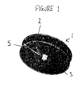
Figure 1 is a perspective view of an embodiment of an apparatus for curling
hair;
Figure 2 is a side view of the apparatus of Figure 1;
Figure 3a is a plan view of the apparatus of Figure 1;
Figure 3b shows a cross section through the apparatus of Figure 1, along the
line A-A shown
in Figure 3a;
Figure 4 illustrates the apparatus of Figure 1 being heated using
straightening irons;
Figure 5a is a side view of an alternative embodiment of apparatus for curling
hair, in an
open configuration;
Figure 5b is a side view of the apparatus of Figure 5a, in a closed
configuration;
CA 03006437 2018-05-25
WO 2017/098282 PCT/GB2016/053917
Figure 6a shows a cross section through the apparatus of Figure 5a, along the
line B-B, the
apparatus in the open configuration;
Figure 6b shows a cross section through the apparatus of Figure 5b, along the
line C-C, with
the apparatus in the closed configuration;
Figure 7 is a schematic representation of a heater adapted for heating the
apparatus
illustrated in Figures 1 to 6b;
Figure 8a is a schematic representation showing a section of hair at the
commencement of
winding onto the apparatus;
Figure 8b is a schematic representation showing a section of hair at the end
of winding onto
the apparatus;
Figure 8c is a schematic representation showing the section of hair at the end
of the winding
process with the apparatus closed;
Figure 9a is a perspective view of a further embodiment of an apparatus for
curling hair, in
an open configuration;
Figure 9b is a side view of the apparatus of Figure 9a;
Figure 10 is a side view of an alternative embodiment of an apparatus for
curling hair, in an
open configuration;
Figure 11 a is a side view of an alternative embodiment of an apparatus for
curling hair, in an
open configuration;
Figure llb is a side view of the apparatus of Figure 11a, in a closed
configuration; and
Figure 11c shows a cross section through the apparatus of Figure 11b, along
the line D-D,
with the apparatus in the closed configuration;
6
CA 03006437 2018-05-25
WO 2017/098282 PCT/GB2016/053917
Detailed Description of the Preferred Embodiments
Referring now to Figures 1 to 3, an embodiment of a hair curling apparatus
takes the form of
a curler shown generally at 1. The curler 1 comprises two spaced apart side
members 2,3 connected
by a connector portion 4 (See Figure 2). In the illustrated embodiment the
connector portion 4 is
hollow but this is not essential. In this example both of the side members 2,3
are substantially
circular in shape and substantially flat in profile, as shown more clearly in
Figure 2. The curler 1 is
fabricated from a silicon rubber that is thermally conductive. As shown in
Figure 3a, either or both
of the side members 2, 3 may be formed with holes 8 therein. The connector
portion 4 could also be
provided with such holes. Where provided, the holes 8 would typically be made
across the whole
of one or both of the side members 2, 3.
To use the curler 1 a section of hair is wound around the connector portion 4.
The hair can
either be wound from the root to the free end, or from the free end to the
root. As shown in the
drawings, the curler 1 is preferably provided with a slot 5 in one of the
spaced apart side members.
In the illustrated example the slot 5 is a narrow 'V' shape. The slot 5
extends from the edge of the
side member 3 and is used to secure the end of the section of hair, by simply
tucking the end of the
hair section into the slot 5. Since the side members 2,3 are made from a
resilient material the hair
ends pushed into the slot 5 are gripped by the side member 3. Alternative
means of securing the
hair in the curler 1 could be used.
Once the section of hair has been wrapped around the connector portion 4 and
secured in the
curler 1, a pair of conventional hair straightening irons 6 are used to heat
the curler 1, by simply
clamping the straightening irons 6 around the curler 1 as shown in Figure 4.
Preferably the
straightening irons 6 are clamped around the ruler 1 for a period of around 30
seconds. Rather than
7
CA 03006437 2018-05-25
WO 2017/098282 PCT/GB2016/053917
using straightening irons 6, a heater 16 of the type shown in Figure 7 having
heater plates 17a, 17b
of a shape that corresponds to the shape of the curler 1 may be used. The
advantage of using a
heater of the type shown in Figure 7, which may function in the same way as
hair straightening
irons is that heat is distributed to the hair in the curler more evenly.
Typically, a user would use a number of curlers 1 during one hair styling
session, sectioning
the hair into groups and winding each section onto a separate curler 1. The
user would then heat
each curler 1 in turn until all of the curlers have been heated. Since the
side members 2, 3 are
thermally conductive, the heat from the straightening irons is transferred to
the hair. The diameter of
each of the side members 2,3 is substantially greater than length of the
connector 4. In the
illustrated example the diameter Z of the curler 1 is 73mm and the length of
the connector 4, shown
at X, is 14mm. Having wide side members ensures that all the hair to be heated
is contained within
the curler 1, no matter how thickly it is wound, and this also ensures that
heat is distributed evenly
to all of the air contained within the curler 1. A hood drier could be used to
heat the curlers 1 as an
alternative to using hair straighteners. The curler 1 is preferably left with
the hair wrapped around it
until it cools. Once cooled the hair can be easily unwrapped from the curler
1, forming perfect
spiral curls that do not quickly drop out of the hair. Serial curls may be
formed with the curler 1
because the section of hair can be wound around the curler rather than the
curler being rolled up the
section of hair, as is conventional.
In a preferred embodiment, the side members 1 are fabricated from a material
which
changes colour when heated to the optimum temperature, and then reverts to the
original colour
when cooled. This would help a user identify which curlers 1 had been heated
sufficiently, and
would also alert a user as to when the curlers were cool enough to remove.
The diameter, Y, of the connector portion 4 may be varied to provide different
types of curl.
8
CA 03006437 2018-05-25
WO 2017/098282 PCT/GB2016/053917
For example, use of an curler 1 with a narrow diameter connector portion 4
will result in tight spiral
curls, whereas a curler 1 with a wide diameter connector portion 4 will result
in larger waves.
The length of the connector portion 4 is important, since the apparatus 1
needs to be able to
be gripped between the plates of straightening irons. In the example shown the
length of the
connector portion 4 is 14mm.
Figures 5 and 6 illustrate an alternative embodiment of the apparatus of the
invention, which
takes the form of a curler shown generally at 10. Curler 10 comprises two
spaced apart side
members 12 ,13 connected by a connector portion 14. In this embodiment of the
invention one of
the side members 13 is substantially flat in profile and the other side member
12 is curved in shape.
The side member 12 which is curved in shape is configured such that it has two
fixed states. The
first fixed state is illustrated in Figures 5a and 6a, where the side member
12 is convex in shape and
curves away from the other side member 13. This is the open configuration of
the curler 10, and
allows for hair to be wound around the connector portion 14. The second fixed
state is illustrated
in Figures 5b and 6b, whereby the curved side member 12 has been folded over
so that it is now
concave in shape and curves over the top of the connector portion 14 and the
other side member 13.
This is the closed configuration of the curler 10, and allows hair wrapped
around the connector
portion 14 to be secured within the curler 10. The curler 10 is fabricated
from a silicon rubber that is
thermally conductive.
To use this embodiment of the apparatus, the hair is wound around the
connector portion 14
of the curler 10 in the same manner as before, with the apparatus in the
first, open configuration.
The steps of winding a section of hair around the connector portion 4 of the
curler 1 are best
shown in Figured 8a to 8b.
9
CA 03006437 2018-05-25
WO 2017/098282 PCT/GB2016/053917
The embodiment illustrated in Figures 5 and 6 may also be provided with holes
18 in either
or both of the side members 12, 13 as shown in Figures 5a and 5b. The curler
10 may also, or
alternatively, be provided with holes 7 in the connector portion 14, which is
preferably hollow. In
the figures, the holes 18, 7 are only shown applied to half of the curler 10
to illustrate different
embodiments of the curler 10. If holes 18, 7 are present they are preferably
evenly spaced around
the side members 12, 13 and/or the connector portion 14. The holes 18, 7 are
an optional feature
which allow circulation of air to hair wound around the connector portion 14
which may help hasten
the drying of wet hair within the curler 10.
An end of the section of hair may be secured in a slot 15 in the substantially
flat side
member 13 as before and as shown in Figure 8a. The section of hair is wound
around the connector
portion 14 and upon itself to form a coil as shown in Figure 8b. The curved
side member 12 is then
folded over, such that the curler 10 is now in the second, closed
configuration as shown in Figure
8c. The curved side member 12 now covers the other side member 13 and secures
the hair inside
the curler 10. Straightening irons, or another heat source, are then used to
heat the curler 10 in the
same way as previously described.
By forming a coil of hair that is narrow in width compared to the diameter of
the coil, the
hair contain in the curler may be heated and cooled both rapidly and evenly,
resulting in a lasting
curl.
Figures 9a and 9b illustrate an alternative embodiment of the apparatus of the
invention,
which is similar in shape to the embodiment illustrated in Figure 5a and takes
the form of a curler
shown generally at 20. Curler 20 comprises two spaced apart side members 22,
23 connected by a
connector portion 14. As with the previous embodiment of the invention, one of
the side members
23 is substantially flat in profile and the other side member 22 is curved in
shape. The side member
CA 03006437 2018-05-25
WO 2017/098282 PCT/GB2016/053917
22 which is curved in shape is configured such that it has two fixed states.
The first fixed state is
illustrated in Figure 9a, where the side member 22 is convex in shape and
curves away from the
other side member 23. This is the open configuration of the curler 20, and
allows for hair to be
wound around the connector portion 14. The second fixed state is the same
as that illustrated in
Figures 5b, whereby the curved side member 22 is folded over so that it is now
concave in shape
and curves over the top of the connector portion 14 and the other side member
23. This is the
closed configuration of the curler 20, and allows hair wrapped around the
connector portion 14 to
be secured within the curler 20. The curler 20 is fabricated from a silicon
rubber that is thermally
conductive.
In this embodiment the curler 20 is provided with a number of holes 18 18' on
either one of,
or both side members 23, 24. As described in relation to Figures 5 and 6,
holes 7 may also be
present on the connector portion 14. The holes 18, 18' , 7, are an optional
feature which allow
circulation of air to hair wound around the connector portion 14. The
substantially flat side member
23 is also provided a number of protrusions 24 spaced around the outer
circumference of the side
member 23 and oriented inwardly, towards the opposing side member 22. The
protrusions 24 help
to grip the hair and help prevent the curler 20 from slipping off the hair
when the curler 20 is in the
closed configuration with hair wrapped around the connector portion 14. The
curler 20 may
additionally be provided with a slot (not shown) for securing the end of a
strand of hair as described
in relation to the previous embodiment.
Figure 10 illustrates a further alternative embodiment of the apparatus of the
invention,
which is similar in shape to the embodiment illustrated in Figure 9a and takes
the form of a curler
shown generally at 30. Curler 30 comprises two spaced apart side members 32,
33 connected by a
connector portion 14. As with the previous embodiment of the invention, one of
the side members
11
CA 03006437 2018-05-25
WO 2017/098282 PCT/GB2016/053917
33 is substantially flat in profile and the other side member 32 is curved in
shape. In this
embodiment of the apparatus, the curved side member 32 is provided with a
plurality of protrusions
25 spaced around the outer circumference of the side member 32. As with the
previous
embodiment, the protrusions 25 help to grip the hair and help prevent the
curler 30 from slipping off
the hair when the curler 30 is in the closed configuration with hair wrapped
around the connector
portion 14. The curler 30 may additionally be provided with a slot (not shown)
for securing the end
of a strand of hair as described in relation to the previous embodiments.
Figure 11 a illustrates a further alternative embodiment of the apparatus of
the invention,
which is similar in shape to the embodiment illustrated in Figure 9a and takes
the form of a curler
shown generally at 40. Curler 40 comprises two spaced apart side members 42,
43 connected by a
connector portion 14. As with the previous embodiment of the invention, one of
the side members
43 is substantially flat in profile and the other side member 42 is curved in
shape. In this
embodiment of the apparatus, both of the side members 42, 43 are provided with
a plurality of
protrusions 25, 24 spaced around the outer circumference of each side member
42, 43. As with the
previous embodiment, the protrusions 25, 24 help to grip the hair and help
prevent the curler 40
from slipping off the hair when the curler 40 is in the closed configuration,
illustrated in Figure 11b,
with hair wrapped around the connector portion 14. As shown in Figure 11c, the
protrusions, 25, 24
are preferably spaced around the circumference of each side member 42, 43 such
that when the
curler 40 is in the closed configuration of Figure 11b, one set of protrusions
25 are located in
between the other set of protrusions 24. The curler 40 may additionally be
provided with a slot (not
shown) for securing the end of a strand of hair as described in relation to
the previous embodiments.
The embodiments of the apparatus illustrated in Figures 9a to 11c may include
holes 18, 18'
on either or both of the side members. Alternatively, or additionally, the
apparatus may include
12
CA 03006437 2018-05-25
WO 2017/098282 PCT/GB2016/053917
holes 7 on the connector member 14. The holes 18, 18', 7 may help heated hair
to cool more
quickly, and/or wet hair to dry more quickly.
13