Sélection de la langue

Search

Sommaire du brevet 3006948 

Énoncé de désistement de responsabilité concernant l'information provenant de tiers

Une partie des informations de ce site Web a été fournie par des sources externes. Le gouvernement du Canada n'assume aucune responsabilité concernant la précision, l'actualité ou la fiabilité des informations fournies par les sources externes. Les utilisateurs qui désirent employer cette information devraient consulter directement la source des informations. Le contenu fourni par les sources externes n'est pas assujetti aux exigences sur les langues officielles, la protection des renseignements personnels et l'accessibilité.

Disponibilité de l'Abrégé et des Revendications

L'apparition de différences dans le texte et l'image des Revendications et de l'Abrégé dépend du moment auquel le document est publié. Les textes des Revendications et de l'Abrégé sont affichés :

  • lorsque la demande peut être examinée par le public;
  • lorsque le brevet est émis (délivrance).
(12) Demande de brevet: (11) CA 3006948
(54) Titre français: DETECTION DE FUITES D'UN AGENT DE REDUCTION DE LA TRAINEE ET SYSTEME DE RECUPERATION
(54) Titre anglais: DRAG REDUCING AGENT LEAK DETECTION AND RECOVERY SYSTEM
Statut: Examen
Données bibliographiques
(51) Classification internationale des brevets (CIB):
  • F17D 05/02 (2006.01)
(72) Inventeurs :
  • HYATT, ROBERT R. (Etats-Unis d'Amérique)
  • HYATT, GEORGE W. (Etats-Unis d'Amérique)
(73) Titulaires :
  • PIPE LINE UNIQUE SERVICES LLC
(71) Demandeurs :
  • PIPE LINE UNIQUE SERVICES LLC (Etats-Unis d'Amérique)
(74) Agent: SMART & BIGGAR LP
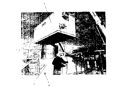
(74) Co-agent:
(45) Délivré:
(22) Date de dépôt: 2018-06-01
(41) Mise à la disponibilité du public: 2018-12-01
Requête d'examen: 2021-03-17
Licence disponible: S.O.
Cédé au domaine public: S.O.
(25) Langue des documents déposés: Anglais

Traité de coopération en matière de brevets (PCT): Non

(30) Données de priorité de la demande:
Numéro de la demande Pays / territoire Date
15/995,186 (Etats-Unis d'Amérique) 2018-06-01
62/513,521 (Etats-Unis d'Amérique) 2017-06-01

Abrégés

Abrégé anglais


A leak detection and recovery system for use with DRA equipment. The system is
intended to reduce the risk of a chemical release into the environment, namely
the soil, ground
water, and waterways. The system may provide clean collection of leaked DRA,
early detection
of DRA leaks, immediate notification of DRA leaks, and re-use of leaked DRA
through clean
recovery with no hazardous waste disposal.

Revendications

Note : Les revendications sont présentées dans la langue officielle dans laquelle elles ont été soumises.


WHAT IS CLAIMED IS:
1. A system comprising:
an upper section comprising injection equipment; and
a lower section comprising a catch basin;
where the catch basin is positioned such that leaks from the injection
equipment of the upper
section are collected in the catch basin.
2. The system of Claim 1 where:
the catch basin is located entirely within the lower section;
the upper section is located above the lower section; and
the upper section fully covers the lower section, such that the upper section
protects the catch basin from contamination from ambient elements.
3. The system of Claim 1 where the catch basin has a floor that slopes to a
single low point.
4. The system of Claim 3 where the lower section further comprises a drain
located at the
low point of the catch basin.
5. The system of Claim 4 where the drain is in fluid communication with the
exterior of the
lower section via a valve.
6. The system of Claim 4 further comprising a level detection instrument
7

7. The system of Claim 6 where the level detection instrument is located at
the low point of
the catch basin.
8. The system of Claim 6 where the level detection instrument is in
communication with a
PLC capable of shutting down the injection equipment located within the upper
section.
9. The system of Claim 1 where the injection equipment is DRA injection
equipment.
10. The system of Claim 1 where:
the lower section is generally rectangular with closed sides and an open top;
the upper section is generally rectangular with closed sides and a partially
open
bottom, where the bottom of the upper section has the same dimensions as the
top of the
lower section; and
the upper section sits atop the lower section and such that the lower section
is
protected from contamination from ambient elements.
11. A method of detecting and recovering DRA leaks, the method comprising;
injecting DRA into a pipeline via injection equipment located in an upper
section,
where the upper section is located above a lower section; and
catching leaks from the injection equipment in a catch basin located in the
lower
section, where the catch basin is protected from contamination from ambient
elements.
12. The method of Claim 11 further comprising detecting leaks from the
injection equipment.
8

13. The method of Claim 12 further comprising detecting leaks via a level
detection
instrument located at a low point in the catch basin, where the catch basin
slopes downward at all
points to the low point such that all leaked DRA from the injection equipment
travels to the low
point
14. The method of Claim 13 further comprising shutting down the injection
equipment when
the level detection instrument detects a leak.
15. The method of Claim 14 where shutting down the injection equipment when
the level
detection instrument detects a leak comprises:
transmitting a signal from the level detection instrument to a PLC when the
level
detection instrument detects a level; and
shutting down the injection equipment when the PLC receives the signal
indicating that the level detection instrument detects the level.
16. The method of Claim 13 further comprising notifying a person or remove
PLC when the
level detection instrument detects a leak.
17. The method of Claim 11 further comprising collecting leaked DRA from
the catch basin
via a drain located at a low point in the catch basin, where the catch basin
slopes downward at all
points to the low point such that all leaked DRA from the injection equipment
travels to the low
point.
9

18. The method of Claim 16 where collecting leaked DRA from the catch basin
via the drain
comprises opening a valve in fluid communication with the drain.
19. The method of Claim 16 further comprising re-using the leaked DRA.

Description

Note : Les descriptions sont présentées dans la langue officielle dans laquelle elles ont été soumises.

DRA LEAK DETECTION AND RECOVERY SYSTEM
BACKGROUND OF THE INVENTION
Cross Reference.
[0001] This application is based on and claims priority to U.S. Provisional
Patent
Application Serial No. 62/513,521 filed June 1, 2017.
Field of the Invention.
[0002] This invention relates generally to a leak detection and recovery
system, and more
particularly, but not by way of limitation, to a system for use with drag
reducer injection
equipment that prevents loss and contamination of leaking DRA, as well as
providing for
detection of the leak and recovery of the leaked DRA.
Description of the Related Art.
[0003] Drag reducing agent (DRA) is often injected into pipelines to reduce
drag and
associated turbulence within the pipeline. DRA is dangerous, however, if
released into the
environment, namely the soil, ground water, and waterways, such as through DRA
storage or
injection equipment leaks. Furthermore, DRA that leaks from storage or
injection equipment is
subject to contamination, and thus cannot be reused and must be disposed of
through incineration
or remediation. This can be expensive, both in terms of the loss of the DRA
chemicals
themselves, which must then be replaced, and the actual expense of disposal.
[0004] Based on the foregoing, it is desirable to provide a system of DRA leak
detection
and recovery.
[0005] It is further desirable for such system to provide clean collection of
leaked DRA,
eliminating the opportunity for contamination and allowing the DRA to be
reused.
CA 3006948 2018-06-01

[0006] It is further desirable for such system to provide leak detection to
alert an operator
to the presence of a leak and allow the leak to be repaired quickly.
[0007] It is further desirable for such system to allow immediate reuse of the
leaked
DRA, eliminating the need for hazardous waste disposal.
[0008] It is further desirable for such system to prevent environmental damage
due to
DRA leaks.
SUMMARY OF THE INVENTION
[0009] In general, in a first aspect, the invention relates to a system
comprising an upper
section comprising injection equipment and a lower section comprising a catch
basin. The catch
basin may be positioned such that leaks from the injection equipment of the
upper section are
collected in the catch basin. The catch basin may be located entirely within
the lower section,
while the upper section may be located above the lower section. Thus, the
upper section may
fully cover the lower section such that the upper section protects the catch
basin from
contamination from ambient elements.
[0010] The catch basin may have a floor that slopes to a single low point. The
lower
section may further comprise a drain located at the low point of the catch
basin. The drain may
be in fluid communication with the exterior of the lower section via a valve.
[0011] The system may further comprise a level detection instrument, which may
be
located at the low point of the catch basin. The level detection instrument
may be in
communication with a PLC capable of shutting down the injection equipment
located within the
upper section.
[0012] The injection equipment may be DRA injection equipment. The lower
section
may be generally rectangular with closed sides and an open top, while the
upper section may be
2
CA 3006948 2018-06-01

generally rectangular with closed sides and a partially open bottom. The
bottom of the upper
section may have the same dimensions as the top of the lower section and the
upper section may
sit atop the lower section such that the lower section is protected from
contamination from
ambient elements.
[0013] In a second aspect, the invention relates to a method of detecting and
recovering
DRA leaks, the method comprising: injecting DRA into a pipeline via injection
equipment
located in an upper section, where the upper section is located above a lower
section; and
catching leaks from the injection equipment in a catch basin located in the
lower section, where
the catch basin is protected from contamination from ambient elements.
[0014] The method may further comprise detecting leaks from the injection
equipment.
Specifically, leaks may be detected by a level detection instrument located at
a low point in the
catch basin, where the catch basin slopes downward at all points to the low
point such that all
leaked DRA from the injection equipment travels to the low point. The method
may further
comprise shutting down the injection equipment when the level detection
instrument detects a
leak. Shutting down the injection equipment may comprise transmitting a signal
from the level
detection instrument to a PLC when the level detection instrument detects a
level and shutting
down the injection equipment when the PLC receives the signal indicating that
the level
detection instrument detects the level. The method may further comprise
notifying a person or
relaying a signal to a remote PLC when the level detection instrument detects
a leak.
[0015] The method may further comprise collecting leaked DRA from the catch
basin via
a drain located at a low point in the catch basin, where the catch basin
slopes downward at all
points to the low point such that all leaked DRA from the injection equipment
travels to the low
point. Collecting leaked DRA from the catch basin via the drain may comprise
opening a valve
3
CA 3006948 2018-06-01

in fluid communication with the drain. The method may further comprise re-
using the leaked
DRA.
BRIEF DESCRIPTION OF THE DRAWINGS
[0016] Figure 1 is a perspective view of the system of the present invention
during
assembly; and
[0017] Figure 2 is a top diagrammatic view of the system; and
[0018] Figure 3 is a side diagrammatic view of the system.
[0019] Other advantages and features will be apparent from the following
description and
from the claims.
DETAILED DESCRIPTION OF THE INVENTION
[0020] The devices and methods discussed herein are merely illustrative of
specific
manners in which to make and use this invention and arc not to be interpreted
as limiting in
scope.
[0021] While the devices and methods have been described with a certain degree
of
particularity, it is to be noted that many modifications may be made in the
details of the
construction and the arrangement of the devices and components without
departing from the
spirit and scope of this disclosure. It is understood that the devices and
methods are not limited
to the embodiments set forth herein for purposes of exemplification.
[0022] In general, in a first aspect, the invention relates to a leak
detection and recovery
system for use with DRA equipment. The system is intended to reduce the risk
of a chemical
release into the environment, namely the soil, ground water, and waterways. It
may further
reduce the need and risk of disposing of a chemical release through
incineration or remediation.
These benefits may arise from the system when used as part of a DRA injection
skid.
4
CA 3006948 2018-06-01

[0023] As described below, the system may provide clean collection of leaked
DRA,
early detection of DRA leaks, immediate notification of DRA leaks, and re-use
of leaked DRA
through clean recovery with no hazardous waste disposal.
[0024] The system may comprise an upper section 1, a tank 2, and a lower
section 3, as
shown in Figure 1. The upper section 1 may house DRA injection equipment,
while the tank 2
may be a storage tank. The upper section 1 may sit atop the lower section 3.
Little or
substantially no part of the upper section 1 may extend laterally beyond the
lower section 3, such
that all or substantially all of the DRA injection equipment may be located
above the lower
section 3. The tank 2 may sit within the lower section 3 and extend upward
into the upper
section 1 or may sit wholly within the upper section, and thus may be fully
enclosed within the
upper section 1 and lower section 3.
[0025] The lower section 3 may comprise a catch basin. The catch basin may be
fully
enclosed. The lower section 3 may be fully covered by the upper section 1.
Thus, the catch
basin may be isolated from any ambient elements, such as rain, snow, dirt,
wind, and sunlight.
The catch basin may be situated such that it may catch any leaks from the DRA
injection
equipment in the upper section 1, such as flanges, fittings, hoses, etc.
Isolating the catch basin
from ambient elements may eliminate cross contamination by these elements,
thus keeping the
DRA from being classified as hazardous waste. Furthermore, the catch basin may
be designed
and constructed to hold the entire volume of the tank as a measure of
insurance against release.
[0026] The catch basin may be sloped to a specific point, such as the middle
of the basin.
A drain may be located at the lowest spot, and the drain may be sloped to one
side. Thus, DRA
leaking from any location within the upper assembly 1 may flow to a single low
point in the
basin. A level detection instrument 4 may be located at this lowest point or
in the drain. The
CA 3006948 2018-06-01

level detection instrument may be capable of detecting any level of liquid.
The level detection
instrument may generate a signal that may be transmitted to an onboard PLC and
tied into the
PLC's logic so as to shut down all functions of the skid upon detecting a
level. Locating the
instrument at the lowest section of the basin may allow for early detection,
thus minimizing the
leak.
[0027] In addition to shutting down the skid upon detection of a leak, the PLC
may
additionally notify people or a remote PLC that the leak detection instrument
has been tripped or
a leak has been detected. Thus, the system may provide for immediate
notification of a DRA
leak.
[0028] Once a leak is detected, the skid is shut down, and the relevant people
are
notified, the DRA may be recovered. The catch basin may have a valve located
at the center
drain, allowing the leaked, yet still contained and uncontaminated, DRA. to be
collected and re-
used.
[0029] Once the leak has been repaired and the leaked DRA has been collected,
normal
operations may resume with no environmental damage, no loss of DRA, and no
expensive
hazardous waste disposal.
[0030] Whereas, the devices and methods have been described in relation to the
drawings
and claims, it should be understood that other and further modifications,
apart from those shown
or suggested herein, may be made within the spirit and scope of this
invention.
6
CA 3006948 2018-06-01

Dessin représentatif
Une figure unique qui représente un dessin illustrant l'invention.
États administratifs

2024-08-01 : Dans le cadre de la transition vers les Brevets de nouvelle génération (BNG), la base de données sur les brevets canadiens (BDBC) contient désormais un Historique d'événement plus détaillé, qui reproduit le Journal des événements de notre nouvelle solution interne.

Veuillez noter que les événements débutant par « Inactive : » se réfèrent à des événements qui ne sont plus utilisés dans notre nouvelle solution interne.

Pour une meilleure compréhension de l'état de la demande ou brevet qui figure sur cette page, la rubrique Mise en garde , et les descriptions de Brevet , Historique d'événement , Taxes périodiques et Historique des paiements devraient être consultées.

Historique d'événement

Description Date
Modification reçue - réponse à une demande de l'examinateur 2023-12-01
Modification reçue - modification volontaire 2023-12-01
Rapport d'examen 2023-10-24
Inactive : Rapport - Aucun CQ 2023-10-21
Lettre envoyée 2023-07-04
Modification reçue - modification volontaire 2021-03-17
Exigences pour une requête d'examen - jugée conforme 2021-03-17
Modification reçue - modification volontaire 2021-03-17
Toutes les exigences pour l'examen - jugée conforme 2021-03-17
Requête d'examen reçue 2021-03-17
Représentant commun nommé 2020-11-07
Requête pour le changement d'adresse ou de mode de correspondance reçue 2019-11-20
Représentant commun nommé 2019-10-30
Demande publiée (accessible au public) 2018-12-01
Inactive : Page couverture publiée 2018-11-30
Inactive : CIB attribuée 2018-09-21
Inactive : CIB en 1re position 2018-09-21
Modification reçue - modification volontaire 2018-08-10
Inactive : Certificat dépôt - Aucune RE (bilingue) 2018-06-12
Demande reçue - nationale ordinaire 2018-06-06

Historique d'abandonnement

Il n'y a pas d'historique d'abandonnement

Taxes périodiques

Le dernier paiement a été reçu le 2024-05-31

Avis : Si le paiement en totalité n'a pas été reçu au plus tard à la date indiquée, une taxe supplémentaire peut être imposée, soit une des taxes suivantes :

  • taxe de rétablissement ;
  • taxe pour paiement en souffrance ; ou
  • taxe additionnelle pour le renversement d'une péremption réputée.

Les taxes sur les brevets sont ajustées au 1er janvier de chaque année. Les montants ci-dessus sont les montants actuels s'ils sont reçus au plus tard le 31 décembre de l'année en cours.
Veuillez vous référer à la page web des taxes sur les brevets de l'OPIC pour voir tous les montants actuels des taxes.

Historique des taxes

Type de taxes Anniversaire Échéance Date payée
Taxe pour le dépôt - générale 2018-06-01
TM (demande, 2e anniv.) - générale 02 2020-06-01 2020-05-21
TM (demande, 3e anniv.) - générale 03 2021-06-01 2021-02-24
Requête d'examen - générale 2023-06-01 2021-03-17
TM (demande, 4e anniv.) - générale 04 2022-06-01 2022-05-25
TM (demande, 5e anniv.) - générale 05 2023-06-01 2023-05-19
TM (demande, 6e anniv.) - générale 06 2024-06-03 2024-05-31
Titulaires au dossier

Les titulaires actuels et antérieures au dossier sont affichés en ordre alphabétique.

Titulaires actuels au dossier
PIPE LINE UNIQUE SERVICES LLC
Titulaires antérieures au dossier
GEORGE W. HYATT
ROBERT R. HYATT
Les propriétaires antérieurs qui ne figurent pas dans la liste des « Propriétaires au dossier » apparaîtront dans d'autres documents au dossier.
Documents

Pour visionner les fichiers sélectionnés, entrer le code reCAPTCHA :


Pour visualiser une image, cliquer sur un lien dans la colonne description du document. Pour télécharger l'image (les images), cliquer l'une ou plusieurs cases à cocher dans la première colonne et ensuite cliquer sur le bouton "Télécharger sélection en format PDF (archive Zip)" ou le bouton "Télécharger sélection (en un fichier PDF fusionné)".

Liste des documents de brevet publiés et non publiés sur la BDBC .

Si vous avez des difficultés à accéder au contenu, veuillez communiquer avec le Centre de services à la clientèle au 1-866-997-1936, ou envoyer un courriel au Centre de service à la clientèle de l'OPIC.


Description du
Document 
Date
(aaaa-mm-jj) 
Nombre de pages   Taille de l'image (Ko) 
Dessins 2018-08-09 3 115
Dessins 2021-03-16 3 120
Description 2021-03-16 6 341
Revendications 2021-03-16 3 114
Description 2023-11-30 6 341
Revendications 2023-11-30 3 124
Dessins 2018-05-31 3 392
Description 2018-05-31 6 230
Abrégé 2018-05-31 1 11
Revendications 2018-05-31 4 84
Dessin représentatif 2018-11-04 1 187
Paiement de taxe périodique 2024-05-30 3 97
Certificat de dépôt 2018-06-11 1 202
Courtoisie - Réception de la requête d'examen 2023-07-03 1 421
Requête d'examen / Modification / réponse à un rapport 2021-03-16 28 1 069
Demande de l'examinateur 2023-10-23 3 147
Modification / réponse à un rapport 2023-11-30 16 542
Modification / réponse à un rapport 2018-08-09 4 92