Note : Les descriptions sont présentées dans la langue officielle dans laquelle elles ont été soumises.
CA 03007524 2018-06-06
Brake pad for a disc brake
The invention relates to a brake pad for a disk brake, in
particular for a utility vehicle, according to the preamble of
claim 1.
In order to detect a permissible wear limit of the friction
lining, it is known to use an electric wear sensor which has a
housing made of a high-temperature resistant, non-electrically
conducting material in which a contact conductor in the form of
a conductor loop is arranged.
This wear sensor is secured in the backing plate of the brake
pad, in the vicinity of a cap which is attached to the backing
plate and with which a pad securing spring which is arranged at
the edge of the backing plate is non-detachably secured on the
brake pad.
In this context, the wear sensor is plugged into a slot in the
backing plate, while the friction lining is hollowed out from
the backing plate in the exit region of the wear sensor.
A brake pad of the generic type is disclosed, for example, in DE
10 2007 049 981 Al. In the mounted position in a pad shaft of a
brake carrier this brake pad is mounted sprung in the radial
direction with the result that it is moved radially in relation
to the brake carrier counter to the spring force which is
applied by the pad securing spring in the travel operation.
CA 03007524 20113--06
2
For operational regions, there is frequent non-uniform, i.e.
uneven wear of the friction faces of a vehicle-side brake disk,
with the result that grooves are formed. When the brake is
released, vibrations can result in radial movement of the brake
pad, with brief overshooting of the grooves, as a result of
which the very brittle housing material of the wear sensor can
be damaged.
Furthermore, said cutout in the friction lining for positioning
the wear sensor correspondingly reduces the wear volume, which
of course has an adverse effect on the service life of the brake
pad.
Moreover, the mounting of the wear sensor in a brake pad
according to the prior art is awkward in that after the pad
securing spring has been attached to the backing plate the wear
sensor has to be guided through between the pad securing spring
and the backing plate, which is not compatible with optimized
efficient fabrication.
The invention is based on the object of further developing a
brake pad of the generic type in such a way that the fabrication
of the brake pad is simplified with little structural
expenditure, and therefore becomes more cost-effective, so that
its service life is extended.
This object is achieved by means of a brake pad having the
features of claim 1. A brake pad for a disk brake, in particular
for a disk brake for a utility vehicle, having a backing plate
which bears a friction lining and to which an element is
CA 03007524 2018-06-06
3
connected which can move in relation to the backing plate, and
having an electric wear sensor is provided, wherein the wear
sensor is arranged on the element which can move in relation to
the backing plate in such a way that it can itself move
relatively to the backing plate. The main plane of the backing
plate extends perpendicularly with respect to a brake
application direction of the pad in a state in which it is
installed into a brake. The wear sensor can be movable parallel
to this main plane.
As a result of this structural configuration, an entire series
of advantages are obtained, which are particularly apparent
insofar as the invention can be implemented in an essentially
cost-neutral fashion.
It is firstly to be noted that the wear sensor is virtually
decoupled from the backing plate or the friction lining. That is
to say when vibrations occur owing to travel said friction
lining no longer moves correspondingly in a radial direction in
the brake so that it is continuously in contact with the same
region of the brake disk. The problems described above, which
arise from the formation of grooves in the brake disk, can now
no longer occur, with the result that the housing of the wear
sensor is no longer subject to the risk of damage.
It is preferred here that the wear sensor be arranged on a pad
securing spring which forms the movable element.
With this configuration it is also advantageous if, when viewed
in a travel direction of the pad securing spring, the wear
CA 03007524 2018-06-06
4
sensor is secured on said backing plate in such a way that it
can be moved in relation thereto. The travel direction is
parallel to the plane in which the backing plate extends.
The wear sensor can be attached to the pad securing spring in a
way in which various structural solutions are conceivable. These
include, for example, the embodiment of a clip which is bent at
preferably 90 to an associated brake disk and to which the wear
sensor is then secured.
This bent clip to which the wear sensor is attached can also
form the securing element.
It is also conceivable to attach the wear sensor to a securing
element, to which the pad securing spring is secured to the
backing plate.
In particular if the securing element is attached centrally to
the backing plate in the circumferential direction of the brake
disk, the wear sensor is also secured in this position with
which oblique wear of the friction lining applies, if at all, as
only a small effect on the response behavior of the wear sensor.
In addition to these purely functional improvements, the
invention also gives rise to significantly simplified mounting
of the wear sensor, since, after attachment of the pad securing
spring, said wear sensor no longer has to be inserted into the
backing plate, which involves feeding it in between the pad
securing spring and the backing plate.
CA 03007524 2018-06-06
,
Moreover, by virtue of positioning the wear sensor outside the
friction lining it is possible to dispense with the
aforementioned cutout, with the result that the wear volume of
the friction lining is completely available, which results in an
5 increase in the service life, with the corresponding cost
advantages.
The wear sensor can be connected in a materially joined fashion,
for example by welding or soldering, but preferably in a
positively locking fashion, to the pad securing spring or to the
securing element, for which purpose latching means which
correspond to one another are provided, said latching means can
be composed, as is provided by a further concept of the
invention, of latching limbs of the housing of the wear sensor
and of undercuts of the securing element or of the bent clip of
the pad securing spring, behind which undercuts the latching
limbs engage.
As a result of this positive engagement, extremely simple
mounting of the wear sensor is possible insofar as the latter
only has to be plugged into an opening, for example in the
securing element, with compression of the elastic latching limbs
which in an end position spread apart, owing to the inherent
restoring forces, in such a way that they engage behind the
undercuts.
In order to protect the wear sensor, the securing element has
two radially oriented clips which are arranged parallel to one
another at a distance from one another and which bound the
radial pathway when the pad securing spring experiences spring
CA 03007524 2018-06-06
6
deflection with respect to the backing plate, with the result
that the wear sensor does not enter into contact with the
backing plate.
In one embodiment, the securing element can also be embodied in
the form of a cap.
It is expedient if the wear sensor is embodied as an end wear
sensor.
Further advantageous embodiments of the invention are
characterized in the dependent claims.
An exemplary embodiment of the invention is described below with
reference to the appended drawings, in which:
figure 1 shows a brake pad according to the prior art in a
front view;
figure 2 shows a brake pad according to the invention, also in
a front view;
figure 3 shows a cross section through a part region of the
brake pad according to line III-III in figure 2;
figure 4 shows part of the brake pad in a sectional plan view;
figure 5 shows a section through the brake pad according to
line V-V in figure 4;
CA 03007524 20113--06
7
figures
6 and 7 show a detail of the brake pad, each in various views;
figure 8 shows a further detail of the brake pad, illustrated
in a perspective view,
figure 9 shows an alternative embodiment variant of a brake pad
according to the invention, also in a front view; and
figure 10 shows a detail of the brake pad shown in figure 9,
also in a front view.
Figure 1 shows a brake pad according to the prior art, with a
backing plate 1 and a friction lining 2 attached thereto.
Projections 4, which pass through slots in a pad securing spring
3, which is embodied as a leaf spring and which is secured to
the backing plate 1 by means of a securing element 5 which is
embodied here as what is referred to as a cap, are formed onto a
marginal edge of the backing plate 1, wherein the pad securing
spring 3 is attached in a radially movable fashion by means of
the securing element 5.
A wear sensor 6, which is introduced into a slot 15, open toward
the pad securing spring 3, in the backing plate 1, and is
positioned in a recess in the friction lining 2, is arranged
laterally next to the securing element 5.
CA 03007524 2018-06-06
8
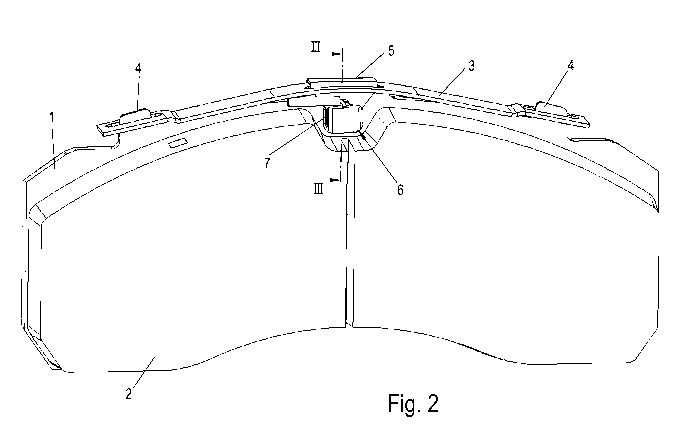
Figure 2 shows a brake pad according to the invention, which
corresponds to the brake pad according to figure 1, with the
exception of the arrangement of the wear sensor 6.
According to the invention, the wear sensor 6 is attached in the
securing element 5, wherein the latter is arranged in the center
with respect to the longitudinal extent of the backing plate 1.
Figure 3 shows a sectional side view of the wear sensor 6 in a
mounted position, where it is possible to see that it has a
housing 8 in which an electrically conductive contact conductor
10 in the form of a cable is guided in the direction of the
friction lining 2, is exposed after the grinding of the contact
conductors 10 by said friction lining 2 owing to the brakes,
which itself gives rise both to an electrically conductive
contact with a brake disk and to a disconnection of the
electrically conductive contact conductor 10. The contact with
the brake disk, which is usually at ground potential of the
associated vehicle, as well as the disconnection which
interrupts a flow of current through the contact conductor 10,
are sensed by a suitable, in particular simple,
electrical/electronic circuit and signaled by the by means of a
suitable display as the reaching of a predefined wear limit.
As can be clearly seen, in particular, in figure 4, the wear
sensor 6 has latching limbs 9 which are integrally formed onto
the housing 8, are elastically deformable and engage in the
mounted position of the wear sensor 6 behind securing device 11
of the securing element 5, with the result that the wear sensor
CA 03007524 2018-06-06
9
6 is secured against dropping out. In this context, the wear
sensor 6 is fitted with its latching limbs 9 at the front
through a cutout 13 in the securing element 5, wherein the
housing 8 rests in an end position against the securing devices
11 which are embodied in an angular shape.
Figure 5 illustrates a sectional rear view of the brake pad,
wherein it is apparent that a part region of the securing
element 5 passes through an opening 7 in the backing plate 1
which is bound, on its side facing the pad securing spring 3, by
a web 1'.
In order to prevent the wear sensor 6 from being pressed against
the web l', and in the process of damaging it in the event of a
radial deflection of the pad securing spring 3 and therefore of
the securing element 5, clips 12, which impact against the web
l' in the event of corresponding radial movement of the securing
element 5 and which are oriented toward the web l', are provided
on the securing element 5, in the area adjacent to the securing
devices 11, wherein the height of the clips 12 is greater than
the height of the latching limbs 9 or of the adjacent parts of
the wear sensor 6.
Figure 6 illustrates a wear sensor 6, also as in figure 7
wherein figure 6 represents the front side of the housing 8
which faces the friction lining 2, while figure 7 shows the rear
side with the integrally formed-on latching limbs 9.
Figure 8 shows the securing element 5 as a cap as a detail, as
is illustrated after mounting on the backing plate 1.
CA 03007524 2018-06-06
,
,
Figures 9 and 10 show an alternative embodiment variant of a
brake pad according to the invention. In this embodiment
variant, the wear sensor 6 is secured in a positively locking
5 fashion to the pad securing spring 3.
In this embodiment variant, the pad securing spring 3 is also
secured at its ends spaced apart from one another to the
projections 4 of the backing plate 1. Instead of the securing
10 element 5 by means of which the pad securing spring 3 is
attached in a radially movable fashion to the backing plate 1,
clip 16 which is preferably bent through 90 with respect to an
associated brake disk and to which the wear sensor 6 is
fastened, preferably in accordance with the attachment to the
securing element 5, as has been explained further above, extends
from a central region of the pad securing spring 3.
CA 03007524 2018-06-06
,
11
List of reference numbers
1 backing plate
l' web
2 friction lining
3 pad securing spring
4 projection
securing element
6 wear sensor
7 opening
8 housing
9 latching limb
contact conductor
11 securing device
12 clip
13 cutout
14 recess
slot
16 clip