Note : Les descriptions sont présentées dans la langue officielle dans laquelle elles ont été soumises.
CA 03008136 2018-02-27
WO 2017/040493 PCT/US2016/049429
UNIVERSAL VEHICLE WITH IMPROVED STABILITY FOR SAFE OPERATION IN
AIR, WATER AND TERRAIN ENVIRONMENTS
REFERENCE TO THE RELATED PATENT APPLICATION(S)
The present Utility Patent Application is based on the Provisional Patent
Application
No. 62/212312 filed on 31 August 2015.
FIELD OF THE INVENTION
The present invention is directed to the vehicle transportation industry, and
particularly,
to unmanned and manned aerial vehicles dynamically adaptable for travel in
aerial, marine, and
surface environments in an autonomous and remotely piloted control regime.
The subject invention is further directed to a vehicle with improved stability
and safety
of operation in either air, water, or terrain environment provided with a
dynamically controlled
mechanism for real-time control either of pitch, roll, and yaw moments by
dynamically
manipulating (passively and/or actively) the vehicles' characteristics which
may include either
of the following: center of thrust, moment arm of center of thrust related to
the center of
gravity, thrust orientation, aerodynamic center of the vehicle, center of
airflow pressure, and the
vehicle's center of gravity and combinations thereof.
In addition, the present invention is directed to a universal vehicle system
designed with
a lifting body which is composed of a plurality of interconnected modules
which are configured
to form an aerodynamically viable contour of the lifting body. The universal
vehicle system
includes a front central module, a rear module, and thrust vectoring modules
displaceably
connected to the front central module and operatively coupled to respective
propulsive
CA 03008136 2018-02-27
WO 2017/040493 PCT/US2016/049429
mechanisms. The thrust vectoring modules are dynamically displaced relative to
the lifting
body (in tilting and/or translating fashion) to direct and actuate the
propulsive mechanism(s) as
needed for safe and stable operation in various modes of operation and
transitioning
therebetween in air, water and terrain environments.
The present invention is also directed to a universal vehicle designed with a
propulsion
system capable of propelling or decelerating the vehicle, and which includes a
tilting nacelle
actuation mechanism which actuates a respective module of the lifting body
structure to adapt
to either of air, water or terrain modes of operations.
In addition, the present invention relates to unmanned or manned aerial
vehicles, and
particularly, to aircraft which use lifting body aerodynamics for achieving a
desired flight
regime of operation. This system expands the aerial system capabilities by
permitting
horizontal flight (generally preferred during cruise/loiter) and vertical
flight (generally preferred
for on-station hovering, take-off, and/or landing) by combining the controlled
lifting body
aerodynamics and vectored propulsion system actuation, while attaining a
seamless safe
transition between the vertical and horizontal flight modes of operation.
The present invention is also directed to a universal vehicle whose
aerodynamic and/or
vectored propulsion qualities permit the vehicle to perform with short runways
(or no runways),
high vehicle density on tarmac, and high through-put.
2
CA 03008136 2018-02-27
WO 2017/040493 PCT/US2016/049429
BACKGROUND OF THE INVENTION
Aerial vehicles capable of vertical and horizontal flight are commonly
categorized as
VTOL (Vertical Take-off and Landing), or STOL (Short Take-off and Landing), or
STOVL
(Short Take-off and Vertical Landing), or VTOSL (Vertical Take-off and Short
Landing) or
V/STOL platforms. These aerial vehicles usually are not capable of using
aerodynamic lift
forces during transition between the take-off and landing flight regimes.
Another disadvantage of the existing V/STOL platform is that tilt rotor and
tilt wing
concepts are generally only halfway efficient in a helicopter system and
halfway efficient in an
airplane system.
U.S. Pat. No. 1,981,700, U.S. Pat. No. 1,981,701, U.S. Pat. No. 2,062,148,
U.S. Pat. No.
2,108,093, U.S. Pat. No. 2,430,820, US. Pat. No. 2,438,309, and U.S. Pat. No.
2,481,379
describe lifting body vehicles that feature specific shapes. However, the
design of these aircraft
systems permit neither the Vertical Take-off and Landing (VTOL), nor the
vertical flight or the
hovering flight. Moreover, the control capabilities of these systems are
limited only to
manipulating the airflow for roll moment control, and controlling pitch and
yaw only by
actuation of trailing edge surfaces. Additional limitations of the prior art
systems operation are
due to mounting the on-board propulsion system in a rigid (fixed) fashion.
Some existing aircraft are designed with tilt wings and tilt rotors. These
vehicles have
shortfalls that are mainly derived from the compromise between the aerodynamic
based flight
(the airplane mode of flight) and powered lift (the helicopter mode of
flight). On one hand, the
requirements for an efficient aerodynamic lift typically come from large
effective lift producing
surface areas as well as the forward speed. On the other hand, in the hovering
flight mode of
3
CA 03008136 2018-02-27
WO 2017/040493 PCT/US2016/049429
operation, where the vehicle's ground speed is zero, the entire lift
generation results from the
powered lift system.
Given the nature of these two contradicting flight modes of operation
(airplane and
helicopter), the efficient powered lift benefits from large, untwisted, and
flexible blades moving
a large volume of air where the available lift must exceed (or at least be
equal to) the vehicle's
weight, while the propulsion for the efficient aerodynamic lift is preferably
achieved with
smaller, twisted, and stiff propellers which only have to overcome the
vehicle's drag as a means
of generating forward ground speed. In essence, the overall efficiencies for
these flight modes
of operation are polar opposites, and have inherently contradicting mechanisms
of achieving
flight.
Tilt wing and tilt rotor vehicles, and their developers have attempted to
balance
efficiency at both end of the spectrum for the airplane and helicopter flight
modes of operation.
For example, large blades are needed for hovering or vertical take-off and
landing. However,
the large blades, when tilted to the airplane mode of flight, generate a large
drag penalty even
though they are attempting to move the entire vehicle forward.
Additionally, the large blades needed for hovering have large impact on the
vehicle's
ground clearance, available wing span, structural stability, overall
mechanical complexity and
safety. Conversely, a small propeller, while best suited for the airplane mode
of flight, will not
efficiently move the required volume of air to offset the vehicle's weight by
means of a
powered lift alone. Thus, the existing tilt wing and tilt rotor vehicles do
not employ small
propellers.
While the optimization for the end point flight modes of operation, i.e., the
airplane
mode and the helicopter mode, is challenging enough, the transition between
the two flight
4
CA 03008136 2018-02-27
WO 2017/040493 PCT/US2016/049429
modes is more perilous. At any interim angle during the tilt evolution between
90 degrees (in
the helicopter mode) and ¨0 degrees (in the airplane mode), the hand-off
between the powered
lift and aerodynamic lift (and vice-versa) often generates aeronautical
problems.
For example, during tilting at take-off, from 90 degrees to ¨0 degrees, there
is a
diminishing lift vector component of force as the thrust vector migrates from
a vertical (90
degrees) to a horizontal (-0 degrees) orientation.
Furthermore, the ground speed is insufficient for the appreciable aerodynamic
lift
generation from the limited available wing area (if the available wing area is
not at stall angles
of attack).
In addition, the aerodynamic phenomena involving complex stall characteristics
are at
play during transition from the airplane mode to the helicopter mode of flight
and vertical
landing. The required twist on the propeller to make the airplane mode
efficient and achieve
higher speed horizontal flight is prone during the helicopter mode of
operation to blade stall.
This is known as a Vortex Ring State, whereby a rotor is enveloped by its own
downwash.
This blade stall phenomena occurs at or above a given rate of descent at low
forward speed.
The irreversible stall condition implies that transitioning to vertical flight
or landing vertically
is extremely dangerous should a descent rate consistent with generating the
sudden loss of lift
be present. Thus, the mismatch of the lift generation from one rotor to the
other causes an
immediate roll moment which may cause catastrophic results.
The above mentioned perils have been flagged by various programs as early as
1964,
such as, for example, with the NASA LVT XC-142A Tilt Wing Program whose
undesirable
flight characteristics included such criteria as the instability at tilt wing
angles between 35 to 80
degrees, high disk loading, excessive downwash, excessive vibration due to the
drive shafts,
CA 03008136 2018-02-27
WO 2017/040493 PCT/US2016/049429
and drive shaft damage due to wing flexing. In the present technology era,
while the military
utilizes the tilt rotor V-22 Osprey, such poses many aerodynamic problems.
Tailsitting vehicles also need improvements in their design and functionality.
The
experimental USN Convair XFY Pogo and Lockheed XFV-1 from the 1950s were
tailsitter
vehicles designed to have vertical take-off and landing capability. The
classification of
tailsitters means that the vehicle completely rests on its tail (rear) section
in a vertical
orientation. In various ways both the Pogo and XFV-1, while also suffering
from flight
transition difficulties (especially after high speed horizontal flight back to
stationary vertical
orientation), mechanical complexity and safety concerns, had an additional
flaw in that wind
gusts played havoc during vertical operation. Even while at rest, the narrow
footprint of the
landing gear system and high vehicle CG (center of gravity) made tailsitter
vehicles susceptible
to tip-over in the presence of high wind.
It is a long-lasting need in the area to provide a vehicle system capable of
safe operation
in and transitioning between the airplane and helicopter (and vice versa)
modes of operation,
where the contradicting requirements for the airplane mode of operation and
the helicopter
mode of operation are effectively balanced. In addition, it is highly
desirable to enhance the
performance of the vehicle by powering the lifting body with a propulsion
system that would
provide the airflow over the lifting body surface to attain continuous lift
during transition
between vertical and horizontal flight modes of operation, and to perform
roll, pitch and yaw
also by other means installed on the vehicle in addition to (or instead of)
controlling the
actuation of trailing edge surfaces.
6
CA 03008136 2018-02-27
WO 2017/040493 PCT/US2016/049429
SUMMARY OF THE INVENTION
It is therefore an object of the present invention to provide an advanced
aviation vehicle
with an enhanced flight envelope by introducing effective V/STOL capability of
uncompromised and balanced operation in, and safe transitioning between the
airplane and the
helicopter modes of operation.
It is, another object of the present invention to provide a robust aerial
vehicle capable of
short take-off, short landing, vertical take-off, and/or vertical landing,
that is compact, easy to
manufacture, capable of both sustained vertical and horizontal flight,
hovering, efficiently and
safely transitioning in any sequence between vertical and horizontal flight
regimes,
launchability from either stationary and/or moving platform, and that is
indifferent to
launching/landing zone surface qualities and/or terrain types utilized during
take-off and/or
landing.
It is a further object of the present invention to provide the aerial vehicle
capable of
V/STOL which is based on merging the lifting body concept with thrust
vectoring while
solving the tilt wing and tilt rotor deficiencies during the flight mode
transition, attained
substantially in two manners: (a) by harvesting the benefits of the lifting
body to create lift at
high angles of attack and achieve favorable stall performance, while
maximizing lift area to
provide useful lift for the vehicle, and (b) by alleviating the requirements
for the propulsion
system based on the available lift of the lifting body during transition, even
at high angles. As a
result, the subject system is capable of achieving sustained vertical flight
and safe transition
with either smaller propeller systems or large diameter blade systems.
The overall fusion of an aerodynamically viable lifting body with thrust
vectoring
permits significant sub-system consolidation and modularity, and provides a
wide operational
7
CA 03008136 2018-02-27
WO 2017/040493 PCT/US2016/049429
range that is highly attractive to end-users, specifically in the Unmanned
Autonomous Vehicle
industry. While the thrust vectoring provides most (or all) of the stability
and control, the
subject invention results in a vehicle having minimal part count and manages
to
compartmentalize sub-systems in a manufacturing and/or end-user friendly
fashion due to the
fact that the trailing edge surfaces are not required to move as the primary
means of the flight
control.
It is also an object of the present invention to achieve high efficiency in
lift generation
of the subject vehicle during flight regimes transition which results in less
power
consumption/draw of the propulsion system, which benefits the vehicle range,
flight envelope,
overall performance, vehicle weight, permissible mission types, on-board
electronics, and/or
propulsion system.
It is another highly desirable object of the subject system to attain a high
degree of
hybridization of the lifting body of the vehicle with thrust vectoring to
introduce features
previously reserved for tail sitting vehicles. The subject system is capable
of operation as a tail
sitter, but has the added feature of rotating about its contact point with the
ground into a prone
position. Alternatively, it can transition out of the prone position into a
semi-vertical or vertical
orientation during take-off. The vehicle's ability to rest on its tail while
performing the flight
mode transition (from or to vertical orientation), further mitigates the
negative (and even
catastrophic) happenstance plaguing V/STOL designs attempted over the past
decades.
In addition, it is an important object of the subject system to utilize
actuated nacelles in
the vehicle as a landing mechanism/apparatus, which also can place the vehicle
in the prone
position on either its top or bottom face should a wing gust broadside the
lifting body area.
8
CA 03008136 2018-02-27
WO 2017/040493 PCT/US2016/049429
Gusts mostly or completely along the vehicle's lateral (span-wise) axis would
flow around the
vehicle since there is minimal surface area facing the wind direction.
Along the same lines of consolidation of the vector thrust, tiling propulsion,
and landing
apparatus, it is another object of the subject system to offer various modes
of ground
locomotion for the subject vehicle while in the prone position. The subject
vehicle may taxi
forward, backward, turn, and rotate in place by means of rotating its nacelles
and providing
vectored thrust from its propulsion system. In operation, if the landing
wheels are actively
driven, the subject system will support tank-like steering and maneuvering.
If, alternatively,
only nacelle rotation (is utilized without thrust from its propulsion system),
the present system
may be modified to prone crawl.
The above stated objectives are made possible (among other of its innovative
steps) by
combining in the subject vehicle the benefits of the aerodynamically viable
lifting body, tilting
nacelle(s), light weight and tailsitter concepts, such that an entirely new
genre of vehicle
emerges that is capable of overcoming inefficiencies and safety issues of the
existing tilt
rotor/wing vehicles while adding completely new capabilities to the lifting
body concept
including tailsitter and tethered flight design features.
In one aspect, the present invention is directed to a universal vehicle for
uncompromised
and balanced air, water and terrain travel in various modes of operation and
safe transitioning
therebetween. The universal vehicle includes a lifting body composed of a
plurality of
cooperating modules, each configured to form the lifting body, having an
aerodynamically
viable contour.
Some of the lifting body modules may be removably and displaceably connected
each to
the other to form a modular lifting body. The cooperating modules of the
lifting body include
9
CA 03008136 2018-02-27
WO 2017/040493 PCT/US2016/049429
at least one thrust vectoring module and at least one propulsive mechanism
operatively coupled
to the thrust vectoring module. The thrust vectoring module is dynamically
controlled to affect
the positioning and actuation of the propulsive mechanism, thus attaining
dynamic
(substantially in real-time) control of the positioning and mode of operation
of the vehicle as
well as transitioning between the modes of operation thereof.
At least one (or more) thrust vectoring module(s) may include a tilting
nacelle module
carrying the propulsive mechanism thereon and rotatively displaceable about an
axis extending
sidewise the lifting body.
The lifting body may be designed with light weight cooperating upper and lower
lifting
body surfaces (shells) which define an internal volume therebetween when
displaceably
connected one to another. The lifting body further includes a central front
module, and a rear
module coupled to said central front module. The tilting nacelle module may be
displaceably
(rotatively or translationally) disposed at each side of the central front
module for symmetric or
asymmetric actuation of the propulsive mechanism in a controlled direction.
Each of the central front module, rear module, and the nacelle module(s) may
be formed
with a lower shell and an upper shell contoured to cooperate with each other
at their respective
peripheries, and to form a respective internal volume when the upper and lower
shells are
connected. The internal volume may be utilized as a payload compartment or
compartment for
accommodating the vehicle's components selected from a group including
avionics system,
sensors system, weapon system, navigation and guidance system, communication
system,
power system, energy storage unit, payload system, payload, propulsion system,
fuel cell,
landing gear system, docking system, tether system, flight assist system,
collision avoidance
CA 03008136 2018-02-27
WO 2017/040493 PCT/US2016/049429
system, deceleration system, flight termination system, ballast system,
buoyancy system,
mechanical systems, and electronics.
The nacelle module has a length corresponding to the length of the central
front module,
or corresponding to the length of the lifting body (from front edge to rear
edge), as well as
corresponding to a length exceeding the length of the central front module but
smaller than the
length of the lifting body.
The propulsive mechanism may be positioned at the front end the nacelle
module, and
may be tiltably displaceable about an axis of the nacelle module.
The vehicle further includes at least one stabilizer module positioned in
operative
cooperation with the rear module. The stabilizer module may have a vertical,
horizontal,
dihedral, or anhedral orientation relative to the rear module surface. The
stabilizer module may
be installed at the rear module in a rigidly fixed or deployable fashion.
At least one motor may be positioned in the internal compartment defined in
any of the
lifting body modules. For example, the motor may be located within the
nacelle, and be
operatively coupled to the propulsive mechanism.
The propulsive mechanism may be dynamically controlled to operate in a counter-
rotation regime relative to another propulsive mechanism for generating
airflows over the
lifting body having opposing vorticity flow fields.
The modes of operation affected by the thrust vectoring modules may include
short
take-off, short landing, conventional take-off, conventional landing,
externally assisted take-off,
externally assisted landing, and combinations thereof The thrust vectoring
modules are also
11
CA 03008136 2018-02-27
WO 2017/040493 PCT/US2016/049429
configured to control lateral and/or longitudinal positioning of the vehicle
by controlling the
roll, pitch, and yaw moments thereof.
In operation, the thrust vectoring module is controllably deployed to a
specific position
to create a thrust force by the propulsive mechanism to result in the vehicle
deceleration.
The vehicle may be adapted to carry a superstructure thereon which can be
removably
attached to the vehicle. The thrust vectoring module is controllably deployed
to a position to
create a thrust force from the propulsive mechanism resulting in detachment of
the
superstructure when release (and/or delivery) of the superstructure is needed.
The thrust vectoring module can be controllably rotated to a position where
the
propulsive mechanism strikes at least one module of the vehicle to mitigate
disaster in a crisis
situation or to intentionally terminate flight.
The subject universal vehicle further may include a landing device which is
deployable
when landing mode of operation is pursued.
In addition, the thrust vectoring modules are configured for surface
maneuverability by
alternate actuation of the pair of tilting nacelles (without actuation of the
propulsive
mechanism) to actuate the prone positioned crawling mode of operation. Also,
the thrust
vectoring modules are configured to propel the vehicle in the various modes of
operation
including motion in flight, on the terrain, sub-terrain, on a submersed body
or combinations
thereof
The thrust vectoring modules are configured to rotate in clockwise direction
and in
counter-clockwise direction, with the propulsive mechanisms of each thrust
vectoring module
12
CA 03008136 2018-02-27
WO 2017/040493 PCT/US2016/049429
configured to rotate in two directions. The propulsive mechanism of the thrust
vectoring
module may operate as a pusher, or a tractor.
In another aspect, the present invention is a method of operating a universal
vehicle for
balanced air, water, and terrain travel in various modes of operation and
providing safe
transitioning therebetween. The subject method comprises the steps of:
configuring a lifting body with a plurality of cooperating module contoured to
create a
substantially aerodynamically contoured lifting body,
configuring at least one lifting body module as a thrust vectoring module
operatively
coupled with at least one propulsive mechanism, and
controlling the thrust vectoring module to affect positioning and actuation of
the
propulsive mechanism to dynamically control mode of operation of the vehicle,
and the
transitioning between the modes of operation.
The subject method further includes the steps of:
operating the vehicle in either of vertical flight, hovering flight, on-
station airborne
vertical flight, and horizontal flight, vertical take-off (where an initial or
final resting position
includes vertical position including resting on a trailing edge of a
predetermined module of the
lifting body), horizontal prone crawl position (including resting on a
predetermined area of a
predetermined module of the lifting body), and
transitioning to or from the prone crawl position during the take-off and
landing, as well
as transitioning from the vertical orientation to the prone position on either
a top or bottom face
of the lifting body.
13
CA 03008136 2018-02-27
WO 2017/040493 PCT/US2016/049429
In the subject method, the modes of operation further comprise release,
launch, capture,
and landing from or onto a stationary or moving platform, where the platform
may include at
least one of a structure such as a hitch system, a hook system, a cradle
system, a rail system, a
netting system, and a trailer installed on a host vehicle, said host vehicle
including a surface, a
sub-surface, and aerial, amphibious, or marine structures.
The subject method further assumes the step of:
coupling a motor to the thrust vectoring module for flying the vehicle,
propelling the
vehicle on terrain, propelling the vehicle on a fluid medium, and propelling
the vehicle in a
fluid medium, or
coupling a navigation system to the vehicle, and navigating the vehicle in
flight, while
moving through a fluid medium, or on terrain using the navigation system, or
coupling a control system to the vehicle, and controlling the vehicle in
flight, while
moving through a fluid medium, or on terrain using the control system.
The subject method further comprises the steps of:
configuring the thrust vectoring module as a multi-function actuated thrust
module,
configuring the lifting body with at least one multi-function central lifting
body module,
at least one multi-function rear lifting body module, at
least one multi-function vertical
module, and at least one multi-function horizontal module, installing at least
one component,
internally or externally at at least one of the multi-function thrust module,
central lifting body
module, rear lifting body module, vertical module, and horizontal module,
where the at least
one component includes a component selected from a group including: payload,
weaponization,
14
CA 03008136 2018-02-27
WO 2017/040493
PCT/US2016/049429
counter measures system, communication system, ballast system, sensing system,
suspension
system, braking system, dampening system, airbag, parachute, deceleration
apparatus, drive
apparatus, steering apparatus, vibration apparatus, landing gear apparatus,
charging apparatus,
discharging apparatus, electromagnet device, flight assisting device,
locomotion assisting
device, maneuvering assisting device, docking apparatus with or without
electrical connectivity
to the respective docking base, anchoring device, gripping device, grappling
device, clawing
device, floating device, retrieving device, and capturing device, and
combinations thereof.
The subject method further comprises:
operating the vehicle in a loss mitigation mode of operation to diminish
damages to the
vehicle's modules. The loss mitigation mode of operation is triggered by a
mechanism selected
from a group including: pilot triggered, autonomous pilot triggered, observer
triggered, sensor
triggered, deceleration triggered, acceleration triggered, radar triggered,
transponder triggered,
traffic controller triggered, impact triggered, and combinations thereof.
The subject method further comprises:
operating the vehicle in a flight termination mode triggered by a mechanism
selected
from a group including: pilot
triggered, autonomous pilot triggered, observer triggered,
sensor triggered, deceleration triggered, acceleration triggered, radar
triggered, transponder
triggered, traffic controller triggered, impact triggered and combinations
thereof.
The subject method further includes the steps of:
CA 03008136 2018-02-27
WO 2017/040493 PCT/US2016/049429
applying proofing treatments to the lifting body. The proofing treatment may
be
selected from a group including: bullet proofing, fragmentation proofing,
explosive proofing,
heat proofing, fire proofing, and sand proofing.
In the subject method, a plurality of the propulsive mechanisms are selected
from a
group including propellers, turbines, thrusters, fans, and rockets capable of
accelerating in a gas
or a fluid medium, combustion, glow, electric, self-contained, fuel cell
based, hybrid, pump or
geared propulsive mechanisms, and are installed at predetermined locations on
the lifting body
which are positioned and actuated to control the vehicle roll, pitch, and yaw
moments.
The subject method further comprises the steps of:
controlling stability of the vehicle by manipulation of the vehicle's center
of gravity
along the lateral axis, the longitudinal axis, or the lateral and the
longitudinal axis via
translation, and/or rotation, and/or vibration of internal and/or external
masses.
These and other objects and advantages of the subject invention will be
apparent from
the further detailed description and drawings contained in this Patent
Application.
16
CA 03008136 2018-02-27
WO 2017/040493 PCT/US2016/049429
BRIEF DESCRIPTION OF THE DRAWINGS
FIGS. 1A, 1B and 1C are perspective views of the subject aircraft system
according to one
embodiment where all of the vehicle surfaces and propulsion system are
connected (FIG. 1A),
or displaceable one from another (FIGS. 1B-1C);
FIG. 2 A is a front view of the aircraft shown in FIGS. 1A ¨ 1C, and FIGS. 2B
¨ 2E show
alternate lifting body cross section configurations;
FIG. 3A is a top view of the aircraft shown in FIGS. 1A ¨ 1C with alternate
horizontal
stabilizer configurations (shown in FIG. 3B ¨ 3E);
FIG. 4A is a side view of the aircraft in FIGS. 1A ¨ 1C with alternate
vertical stabilizer
configurations shown in FIGS. 4B ¨ 4E;
FIG. 5A is a perspective view of the embodiment of the subject aircraft with
thrust vectoring
capability with alternate embodiments show in the detail views shown in FIGS.
5B ¨ 5E;
FIG. 6A is a perspective view of the embodiment of the subject aircraft with
omni-directional
nacelle actuation capability with alternate embodiments shown in the detail
views of FIGS. 6B
¨6D;
FIG. 7A and its detail views (FIGS. 7B ¨ 71) illustrate the multi-
functionality of the nacelle
system;
FIGS. 8A ¨ 8F shows several detail views of payload applications pertaining to
the nacelle
system;
FIGS. 9A ¨ 9B show the vehicle embodiments of the subject system where the
actuated
nacelles are shown with the deployed safety devices;
FIGS. 10A ¨ 10E show alternative embodiments of the propulsive system;
17
CA 03008136 2018-02-27
WO 2017/040493 PCT/US2016/049429
FIG. 11 is a perspective view of an embodiment of the subject system with
installed
surfaces/extensions;
FIGS. 12A ¨ 12B show alternative embodiments of the method for manipulating
the fluid flow;
FIGS. 13A ¨ 13B show alternative embodiments of the method for manipulating
the center
gravity of the subject vehicle;
FIGS. 14A ¨ 14B show alternative embodiments of the subject system capable of
manipulating
aerodynamic performance, vehicle stability, and/or vehicle control;
FIG. 15 shows an embodiment of the subject system utilizing a tethered
arrangement;
FIGS. 16A ¨ 16E are representative of different modes of vehicle interaction
with the landing
surface and tail sitting capability (FIG. 16C);
FIGS. 17A ¨ 17E show alternative embodiments of the subject vehicle comprising
forward and
rear section rotation along a span-wise hinge line;
FIGS. 18A ¨ 18E show alternative embodiments of the subject vehicle with over-
sized
interlacing propellers;
FIG. 19 shows an embodiment of the subject system comprising a landing
apparatus released
from the lifting body;
FIG. 20A shows a stationary launch/land structure supported by three mobile
launch
embodiments shown in FIGS. 20B ¨ 20D;
FIG. 21 shows a sequence of positions of the subject vehicle prone crawling by
alternatively
actuating its nacelles;
FIG. 22 shows a prone crawling embodiment of the subject system transitioning
from the
terrain to a fluid medium to the flight;
18
CA 03008136 2018-02-27
WO 2017/040493
PCT/US2016/049429
FIGS. 23A ¨ 23B illustrate two embodiments of the subject system adapted to
marine
applications;
FIG. 24 illustrates a wheeled embodiment of the subject system capable of
taxiing via the
provided thrust;
FIG. 25 illustrates a wheeled embodiment of the subject system during take-off
roll-out;
FIGS. 26A ¨ 26B illustrate an embodiment of the subject system pertaining to
the aircraft
shown in FIGS. 1A ¨ 1C, with additional fluid thrusters for the surface or the
submersed
operation;
FIGS. 27A ¨ 27C illustrate three embodiments of the subject system pertaining
to the actuated
nacelle concept with additional installed fluid thrusters;
FIGS. 28A ¨ 28B illustrate two embodiments of the subject system where fluid
jets/thrusters
are installed in the rear lifting body section;
FIG. 29 illustrates an embodiment comprising auxiliary vehicle deployment
capability; and
FIG. 30 illustrates an embodiment adapted for carrying people or animals.
19
CA 03008136 2018-02-27
WO 2017/040493 PCT/US2016/049429
DETAILED DESCRIPTION OF THE PREFERRED EMBODIMENTS
In the present aircraft design, the effectiveness and versatility of the
vehicle results from
the combined integration of the vehicle's sub-systems and their cross
functionality. The
concept underlying the design and operation of the subject system is not
limited to the use of
sub-systems with exclusively dedicated functions, but rather capable of
multiple function
systems. For example, some of the proposed embodiments combine the thrust
vectoring
nacelles with the landing gear and/or payload compartment. The vehicle body
functions as both
a primary lift generation and avionics/payload compartmentalization, the
trailing edge of the
lifting body, and horizontal and vertical stabilizers, and/or rear vehicle
body and also function
as a landing apparatus.
The aircraft of the present invention, when used as an Unmanned Aerial System,
may be
used to meet various end-user needs such as, but not limited to, security
monitoring, crisis
mitigation, disaster relief, scientific sensing, sensory platform for research
and development of
other sub-systems, transportation, payload delivery, communication, and other
peacetime or
wartime missions.
The following description will present preferred embodiments of the subject
system
with an uninhabited aircraft system detailed as an example. However, the
present invention can
also be applied to an inhabited (manned) aircraft.
An exemplary base model is presented in FIG. lA with a fully fixed aircraft
configuration (where the entire vehicle lifting body is non-actuated and is
assembled in
accordance to the subject design during manufacturing) complemented by
presentation of
actuation regimes of the key systems and/or modifications to the lifting body.
As an example, a
particular propulsive device is described herein. However, the propulsion
system contemplated
CA 03008136 2018-02-27
WO 2017/040493 PCT/US2016/049429
in the subject system may further include propellers, turbines or fans, either
in multiples or
pairings or as a single unit, with any blade count, with or without counter
rotation, centered or
offset, of any diameter and/or twist/pitch, body and/or pod and/or nacelle
and/or tip-mounted,
fixed-mounted and/or allowed to actuate, mounted in series and/or in parallel,
mounted
symmetrically or asymmetrically, and/or configured as a tractor (puller)
and/or a pusher.
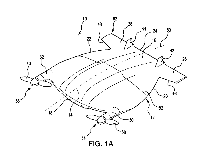
FIGS. 1A ¨ 30 show the subject aircraft system 10 according to one embodiment
of the
present invention which includes a lifting body 12 built with a front section
(module) 14 and a
rear section (module) 16 which are contoured to create an aerodynamic lifting
shape that
connects the front leading edge 18 to the left and right ventral trailing
edges 20 and 22,
respectively. The lifting body 12 also is contoured with the body span
trailing edge 24 which is
contoured with a left horizontal surface 26 and a right horizontal surface 28.
The front section 14 has the left nacelle 30 and right nacelle 32. The
aircraft system
further includes a pair of rotors 34 and 36. The left rotor 34 drives the left
propeller 38, and the
right motor 36 drives the right propeller 40.
A left vertical surface 42 and a right vertical surface 44 are formed at the
body span
trailing edge 24 and comprise the empennage or tail assembly of the aircraft
system 10.
Horizontal leading edges 46 (left) and 48 (right) are formed at the rear
section 16 of the lifting
body 12. There is a transition that is configured between the vertical
trailing edges 20, 22,
respectively and the horizontal leading edges 46, 48 respectively as shown in
FIGS. 1A ¨ 1C.
The aircraft system 10 has a symmetric shape with reference to a central
horizontal axis
(centerline) 50 extending along the horizontal direction (which is the typical
direction of flight).
The centerline 50 is hereinafter referred to as the standard chord line. All
other chord line
21
CA 03008136 2018-02-27
WO 2017/040493 PCT/US2016/049429
references run parallel to the standard chord line 50. A span line 52 extends
perpendicular to
the standard chord line 50, and spans between the left and the right sides of
the aircraft 10.
The vehicle body 12 may be designed with a plurality of lifting body modules.
As
shown in FIGS. 1A ¨ 1C, the front body module 14 and the rear body module 16
can be
removeably connected each to the other. A plurality of other modules may be
created by any
sectioning planes or sectioning curvatures in any orientation and location of
the lifting body 12.
The lifting body modules are contoured to create, when connected each to the
other, an
aerodynamical shape for the lifting body 12.
The lifting body 12 may be manufactured from lower shell 13 and top shell 15
(shown
in FIG. 1B) which are low-weight rigid structures connectable each to the
other at their
periphery.
Similarly, all lift body modules (front central module, rear module, nacelle
modules)
may be formed from the corresponding lower and top shells 19, 21,
respectively, as shown in
FIG. 1C.
Any given lifting body module may house at least one, or any plurality, of
vehicle
components 23, which include avionics, navigation and guidance systems, safety
system,
communication system, sensors system, propulsion system, mechanical system,
power system,
weapons, explosives, landing gear apparatus, docking systems, fuel tank, fuel
cell, payloads,
electronics, and MEMs, separately, or in any combination.
FIG. 2A is a front view of the aircraft 10 shown in FIGS. 1A ¨ 1C with
alternative
lifting body cross section configurations illustrated in FIGS. 2B, 2C, 2D,
and. 2E. FIG. 2B,
illustrates a smaller protrusion centered about the vertical axis 54 and the
horizontal axis 56
extending between sides 58 and 60 of the lifting body 12. FIG. 2C illustrates
a clean cross
22
CA 03008136 2018-02-27
WO 2017/040493 PCT/US2016/049429
section that does not contain any extrusions, FIG. 2D, illustrates protrusions
offset from the
vertical axis 54 and horizontal axis 56, FIG. 2E illustrates a recess into the
cross section that is
offset from the vertical axis 54. Any plurality of cross sections with any
plurality of features
including, but not limited to, that are symmetric, asymmetric, featuring
protrusion or recess that
is centered or offset from either horizontal or vertical axis, of any size, of
any shape, or of any
combination of the above presented features thereof are contemplated in the
subject system
design. The lifting body's cross section thickness and width are generally
variable parameters
which depend on the location of the cross-section of the lifting body and
their angles.
FIG. 3A is a top view of the aircraft 10 shown in FIGS. 1A ¨ 1C with
alternative
horizontal stabilizer configurations presented in FIGS. 3B, 3C, 3D and 3E.
FIG. 3B illustrates
a horizontal stabilizer 62 whose overall span is shorter than the maximum span
of the aircraft
body 12, FIG. 3C illustrates a horizontal stabilizer 62 whose overall span is
greater than the
maximum span of the aircraft body, FIG. 3D illustrates a swept back horizontal
stabilizer
system, and FIG. 3E illustrates a horizontal stabilizer tip 64 configured to
enhance the
aerodynamic performance and the vehicle functionality.
The stabilizer details illustrated in FIGS. 3B ¨ 3E represent only four
examples of
configurations, and other variations are contemplated in the subject design,
including, but not
limited to, configurations where the shape of the horizontal stabilizer 62 may
be symmetric or
asymmetric, with or without leading edge sweep, with or without trailing edge
sweep, with
permanent or varying chord length, thickness and sweep, with or without corner
filleting, with
or without corner chamfering, with or without an airfoil cross section, rigid,
inflatable,
interchangeable, deployable, installed to the lifting body with or without
dihedral or anhedral,
or in any combination thereof
23
CA 03008136 2018-02-27
WO 2017/040493 PCT/US2016/049429
The distance between the left vertical stabilizer 42 and the right vertical
stabilizer 44, as
shown in FIG. 3A, may vary between the length of the full span line to a zero
distance where
the aircraft would have a single centered or offset vertical stabilizer.
FIG. 4A is a side view of the aircraft shown in FIGS. 1A ¨ 1C with alternative
vertical
stabilizer configurations presented in FIGS. 4B, 4C, 4D and 4E. FIG. 4B
illustrates a vertical
stabilizer 66 with a circular shape, FIG. 4C illustrates a vertical stabilizer
66 with leading and
trailing edge sweep, FIG. 4D illustrates an asymmetrical, rounded, and swept
back vertical
stabilizer 66, and FIG. 4E illustrates a swept back, hard corner vertical
stabilizer with recessed
tail wheel.
It is important to note that while the provided detail views of FIGS. 4B ¨ 4E
illustrate
only four exemplary alternative configurations of the vertical stabilizer 66,
any variations
including, but not limited to, implementations where the shape of the vertical
stabilizer may be
symmetric or asymmetric, with or without leading edge sweep, with or without
trailing edge
sweep, constant or varying in chord length and/or thickness, with or without
corner filleting,
with or without corner chamfering, with or without integrated wheel or
castering wheel or
landing gear fixture, with or without airfoil cross section, rigid,
inflatable, interchangeable,
deployable, installed to the lifting body with or without dihedral or
anhedral, or in any
combination of the above listed thereof are also included within the spirit of
the subject aircraft
system 10.
FIG. 5A shows a perspective view of a preferred embodiment of the subject
aircraft
system 10 with thrust vectoring capability attained by means of providing the
lifting body 12
with one or two tilting nacelle modules 70, 72.
24
CA 03008136 2018-02-27
WO 2017/040493 PCT/US2016/049429
In accordance with the embodiment shown in FIGS. 5A ¨ 5E, the aircraft's
lifting body
12 includes a left nacelle module 70 capable of pitching up and down as well
as a right nacelle
module 72 capable of pitching up and down. At least one nacelle tilting
mechanism connects
the right nacelle module 72 to the front central body module 74, and at least
one nacelle tilting
mechanism connects the left nacelle module 70 to the central module 74 such
that the pitching
actuation may occur in unison or independently of each other.
The nacelle tilting mechanism 75, schematically represented in FIG. 5A, may be
housed
entirely in the tilting nacelle modules 70, 72, or entirely in the front
central module 74. Also,
components of the nacelle tilting mechanism 75 may be embedded inside the
nacelle modules
70, 72 and inside the front central module 74 whose cooperative functionality,
under control of
the controller system 77, results in the actuation, rotation, or a combination
of actuation and
rotation motion of at least one or more tilting nacelles 70, 72. The
controller system 77 also
may occupy the inner volumes defined in the nacelle modules 70, 72, front
central module 74,
or be spread through the system.
The front central module 74 and the rear body module 16 may be connected to
each
other and allow the freedom for the left nacelle module 70 and the right
nacelle module 72 to
actuate or rotate about their axis of rotation 76, 78, respectively.
The left nacelle module 70 and its end-face 82 as well as the right nacelle 72
and its
end-face 84 are multipurpose structures as will be detailed in the following
paragraphs.
Although FIGS. 5A ¨ 5E show as an example, a symmetric left and right nacelle
configuration with additional asymmetric nacelle types or configurations with
independent or
dependent mechanisms of deployment are also contemplated in the subject
system.
CA 03008136 2018-02-27
WO 2017/040493 PCT/US2016/049429
FIG. 5B is an elevational side view of FIG. 5A where the subject aircraft
system 10 is
shown in a resting state, hereafter referred as the prone position. In this
embodiment, at least
one nacelle 70 is actuated to pitch relative to the vehicle body 12 whose end-
face 82 (running
along or in proximity to the span line 52) may serve as a point of contact or
as a landing gear
apparatus.
Alternatively, the nacelles, as shown in FIGS. 5D ¨ 5E, may run any chord
length. It is
important to note that all embodiments include at least one or more actuated
nacelles which
may also have additional functionality as detailed in further paragraphs..
FIGS. 5C ¨ 5E are representative of alternate nacelle actuation configurations
that allow
thrust vectoring similar to the embodiment shown in FIG. 5A. FIG. 5C
illustrates an
embodiment with the pitching nacelle modules 70, 72 (one at each side of the
lifting body 12).
In the embodiment shown in FIG. 5C, the fixed horizontal 62 and vertical
stabilizers 66 of that
side do not pitch with the nacelle.
FIG. 5D illustrate an embodiment where the pitching nacelles 70, 72 at each
side of the
lifting body 12 run the length of a full chord line, and where the fixed
horizontal and vertical
stabilizers 62, 66 of that side also pitch with the nacelle.
FIG. 5E is yet a variation of the system shown in FIG. 5D where the body
segment 86
of the vehicle 10 between the vertical stabilizers 66 also deploy with the
nacelle actuation. The
embodiment shown in FIG. 5E may have the capability of rigidly engaging each
other, so that
the two independent nacelle sections 70, 72 become one piece on-demand, or may
be
disengaged on-demand to perform independently.
FIG. 6A is a perspective view of the subject vehicle 10 with an omni-
directional thrust
vectoring nacelle system. FIG. 6B is a top view of the system shown in FIG.
6A, and FIG. 6C
26
CA 03008136 2018-02-27
WO 2017/040493 PCT/US2016/049429
is a cut-off from FIG. 6B showing at least one or more nacelles 90, 92, whose
actuation
provides omni-directional capability, which is achieved by providing the
nacelle 90, 92 with a
pivoting nacelle head 94, 96, and actuating the nacelle head to pivot about
the axle 98. In
addition, the base 100 of the nacelle 90, 92 may be actuated to rotate about
the axis 102.
Alternatively, as shown in FIG. 6D, a similar omni-directional thrust
vectoring
capability is provided by using a ball joint style connection between the
pivoting nacelle 104
and the fixed nacelle base 106.
FIG. 7A is an isometric view of the embodiment shown in FIG. 5B, with at least
one (or
more) multi-functional tilting nacelles 110. FIGS. 7 B ¨ 71 show,
respectively, normal and
perspective views of tilting nacelles 110 which are provided with various
devices attached to
the actuated nacelle (or nacelles) 110 whose attributes include, but are not
limited to, fixed,
deployable, actuated, retractable, being internally or externally mounted,
mounted on the rear
nacelle face or other nacelle surfaces, extending out of the rear nacelle face
or other nacelle
surfaces, passive or driven (powered), with or without sensory capability,
with or without data
gathering capability, with or without energy absorbing devices, with or
without steering or
maneuverability functionality, with or without flight augmentation capability,
with or without
interaction or connectivity to the ground, to other structures, to other
vehicles or to other
external systems, with or without docking capability to other structures,
devices or systems, or
any combinations of the afore-listed attributes.
FIG. 7B shows the tilting nacelle 110 provided with a retractable landing pad
system
112, FIG. 7C shows a sealed rear nacelle face 114 that may or may not be
surface treated for
interaction with the intended contact surface, FIG. 7D shows the tilting
nacelle 110 provided
with a deployed landing gear bogie 116 extending past the rear face 114 of the
nacelle 110,
27
CA 03008136 2018-02-27
WO 2017/040493 PCT/US2016/049429
FIG. 7E shows the tilting nacelle 110 provided with a fixed, in-set, wheel 118
extending past
the rear face 114 of the nacelle 110. FIG. 7F shows the tilting nacelle 110
provided with a
claw-like gripping/grappling/anchoring system 120 extending from the rear face
114 of the
nacelle 110 that may be utilized for example (but not limited to) to secure
the vehicle, allowing
for perching-like capability, and collecting specimen or ground sample 110.
FIG. 7G shows the
tilting nacelle 110 provided with a hook extension 122 extending past the rear
face 114 and
around the nacelle to serve as, but not limited to a catch, sky-hook, or skid.
FIG. 7H shows a
rear nacelle face 114 that features powering and data connectivity port 124
with FIG. 71
showing the tilting nacelle 110 provided with a tank track style apparatus 126
extending around
the rear face 114, as well as the upper face 128 and lower face 130 of the
nacelle 110. It is
important to note that any appendage or system installed on the tilting
nacelle 110 that may
come into contact with or interact with any other object or surface may
additionally comprise
features including, but not limited to, suspension, dampening, detection,
sensing, pivoting,
manipulation, collecting, perching, docking, and maneuvering.
FIGS. 8A ¨ 8F show additional suggested payload functionality for at least one
or more
actuated nacelles presented in FIG. 7A and its embodiments shown in FIGS. 7B ¨
71. FIG. 8A
shows a modified nacelle module 134 formed with a compartment 136 which is
intended for
housing a number of systems such as avionics, safety systems, communication
systems,
propulsion systems, mechanical systems, power systems, fuel tank, fuel cell,
or other generic
payloads or electronics.
FIG. 8B shows the nacelle 134 configured with a payload deployment system 138
capable of payload delivery, for example, of three contained boxes 140, in a
serial/sequential
fashion loaded in the compartment formed in the nacelle 134.
28
CA 03008136 2018-02-27
WO 2017/040493 PCT/US2016/049429
FIG. 8C shows a plurality of payload compartments 142 contoured, for example,
for
tubular payloads 144. However, the compartments may be of any other shape, and
may extend
in parallel or in series.
FIG. 8D shows the nacelle 134 provided with an external payload deployment
system
146, (or payload hardpoint) installed on the surface face 128 of the nacelle
134. FIG 8E shows
the nacelle 134 whose payload compartment 136 may be exposed by actuating
gates (surfaces)
148.
FIG. 8F shows the nacelle 134 provided with a nacelle payload compartment 136
that
blends features from several afore-described embodiments such as, for example,
series and
parallel payload delivery (FIG. 8B), internal (FIGS. 8A, 8B, 8E) and external
compartmentalization (FIG. 8E), and multi-stage delivery mechanism 150 which
includes a
payload receiver (or cartridge) 152 actuated to expose the embedded payload
hardpoints.
FIGS. 9A ¨ 9B show two embodiments of the subject vehicle 10 where at least
one (or
more) actuated nacelles 156 have deployed safety devices 158. FIG. 9A shows an
embodiment
of the subject aircraft 10, in a crisis situation where the flight termination
sequence may be
engaged and damage mitigation may be desirable. As shown in FIG. 9A, the
vehicle 10 has the
actuated nacelles 156 turned such that at least one (or more) propulsive
devices 160 are
destructively engaged with at least one (or more) components of the vehicle
10. In this
situation, at least one (or more) airbag-style or energy absorbing devices 158
have deployed to
mitigate energy transfer on impact. The energy absorbing device 158, if
inflated with air/gas,
may provide buoyancy in case of splash down. FIG. 9B shows another embodiment
of the
subject vehicle 10 where a scenario of flight termination occurs. As shown, a
controlled
29
CA 03008136 2018-02-27
WO 2017/040493 PCT/US2016/049429
descent is actuated which utilizes at least one or more parachutes 162 (or
other deceleration
devices).
FIGS. 10A ¨ 10E show five alternative embodiments of various configurations
and
methods of operation of the propulsion system. FIG. 10A shows the subject
system 10 with a
propulsion system 166 mounted on the body 168 of the nacelle 170. The thrust
vectoring
capability deploys in corresponding fashion with the actuated nacelle 170.
FIG. 10B shows the subject system with the propulsion system 172 mounted on
the
shrouded (or ducted) nacelle module 174 whose thrust vectoring capability
deploys in
conjunction with the actuated nacelle. In FIG. 10B, the trailing edge 176 of
the shroud (or
ducting) may additionally serve as a landing apparatus for which this
embodiment may rest
while in the prone position.
FIG. 10C shows the nacelle 180 provided with a multi-propulsion mechanism 182,
comprising a plurality of propulsive devices 184. The multi-propulsion
mechanism 182 is
actuated by the movement of the nacelle 180. In the embodiment shown in FIG.
10C, any
number of propulsion devices 184 may be installed on the aircraft 10 which may
have
independent actuation timed with the nacelle's deployment. A supporting
structure 186
connecting the propulsion devices 184 to the nacelle 180 may rotate or
translate to allow further
degrees of freedom.
FIG. 10D shows the subject system 10 with at least one or more propulsive
devices 184,
188 that are mounted in a direction which generally is not aligned with the
motion of the
vehicle. The propulsive devices 184 may be mounted on the tilting nacelle 180.
Alternatively,
the propulsive devices 188 may be embedded in the lifting body 12 fixed or
thrust vectored,
CA 03008136 2018-02-27
WO 2017/040493 PCT/US2016/049429
centered or offset, and may be utilized for the vehicle 10 maneuverability or
any other kind of
manipulation of stability and control including stable positioning in a fluid.
FIG. 10E shows the co-joined nacelles 190 having a body section 192 capable of
rotating co-joined nacelles 190 with respect to the section 194 of the lifting
body 12. While the
embodiments shown in FIG. 10A ¨ 10E illustrate nacelle mounted propulsive
devices, it is
contemplated that the propulsive devices may be installed in other locations
of at least one or
more nacelles, lifting body sections, or any combinations thereof
FIG. 11 shows a perspective view of still another embodiment of the subject
aircraft 10
comprising at least one (or more) surface extensions 198, located on at least
one or more
nacelle modules 200. The methods of installation of the surface extensions 198
and extensions
202 may include, but are not limited to, fixed, actuated, deployable,
detachable, or jettison-able
extensions. The surface extensions 198, 202 may be used to control
aerodynamics, stability,
controllability (or any combination thereof) of the vehicle 10. The surface
extensions 198, 202
may also operate in conjunction with at least one or more payloads,
hardpoints, sensors, other
devices, other sub-systems, other docking mechanisms, or any combination
thereof.
FIGS. 12A ¨ 12B show two exemplary embodiments of the methods for manipulating
the fluid flow in the subject system. FIG. 12A shows an embodiment where at
least one or
more surface skin manipulators 206 are utilized. In this embodiment, while the
speed brake
type surfaces 206 are shown as an example, other arrangements for air fluid
flow control may
be used, including deployed surface skin manipulators (passive or actuated)
which would
further manipulate the aerodynamic flow or boundary layer flow surrounding the
surface of the
nacelles or the lifting body. The skin manipulator devices 206 include, but
are not limited to,
31
CA 03008136 2018-02-27
WO 2017/040493 PCT/US2016/049429
skin roughing, texturing, blistering, undulation, indentation, slits, slots,
steps, and other vortex
generation devices.
FIG. 12A also illustrates at least one or more doors 208 exposing other sub-
systems or
sensors.
FIG. 12B shows an embodiment of the subject aircraft system 10 where at least
one (or
more) internal ducts 210 mostly transfer the leading edge flow to another
portion of the vehicle,
so that the energy can be injected into any other location of the vehicle's
surrounding boundary
layer. Further, methods capable of inserting energy into the surrounding fluid
include
combinations of, but are not limited to, energization of flow via ducting,
venting, sucking,
vibrating, heating, cooling, and MEMs (Microelectromechanical systems).
FIGS. 13A ¨ 13B show two embodiments of methods for manipulating the center of
gravity of the subject vehicle system 10. FIG. 13A shows an embodiment where
at least one
span-wise cavity (or guide) 210 permits span-wise movement of an internal mass
(or ballast)
212, so that the center of gravity can shift laterally, to manipulate the
vehicle's stability, control,
or both. The span-wise shifting mass system 214 may be further used to counter
balance
asymmetric mass distribution possibly due the jettisoning of at least one or
more payloads
and/or sub-systems.
FIG. 13B shows an embodiment of the subject aircraft system 10 where a chord-
wise
cavity or guide 216 allows the chord-wise movement of an internal mass 218, so
that the center
of gravity shifts longitudinally, to control the vehicle's stability. The
chord-wise shifting mass
system 220 may be further used to aid in the transitioning between vertical
and horizontal
modes of operation, in addition to counter-balancing an asymmetric mass
distribution possibly
due the jettisoning of at least one or more payloads and/or sub-systems.
32
CA 03008136 2018-02-27
WO 2017/040493 PCT/US2016/049429
While FIGS. 13A ¨ 13B depict a single guide 210 and 216. However, multiple
guides
containing one or more masses, installed in any orientation are contemplated
in the present
system. This may provide the center of gravity management sub-system and may
provide any
degree of freedom to the moving mass or masses 212, 218 to achieve the desired
results.
FIGS. 14A ¨ 14B show two embodiments of the subject aircraft system 10 capable
of
additional control of the aerodynamic performance and vehicle stability. FIG.
14A shows one
(or more) ventral trailing edge surface actuators 222 by means of which the
camber and span of
the lifting body may be controlled. FIG. 14B shows one or more fixed or
deployable
membranes which may be fabric or mesh 224 housed along the ventral trailing
edge 226
capable of extending along the span of the horizontal surface leading edge
228. It is important
to note that such devices may be further installed within pairs and
symmetrically about the
standard chord line.
FIG. 15 shows an embodiment of the subject aircraft system 10 where the
vehicle 12 is
connected via a tether 230 to a fixed or moving connection point 232 that may
be aerial,
grounded, amphibious, or marine. The tether 230 may carry electricity, fiber
optics, other
signal carrying components, or any combination thereof, in addition to the
structural, load
bearing tether structure. The tether connection 234 may be situated on any
location thereof, so
that the connection 234 has the engaging capability, as well as the
disengaging capability.
The tethered method of operation permits tethered flight capability with the
added
benefit of disengaging the tether for on-command fly-away. Additionally, at
least one or more
tethers 230 may be connected to at least one or more towed objects 232 that
are being
transported by the vehicle 12. The towed objects 232 may comprise a singular,
or multitude, or
33
CA 03008136 2018-02-27
WO 2017/040493 PCT/US2016/049429
combination of: payloads, such as, nets, banners, flags, targets, capture
devices, or other
vehicles.
FIGS. 16A ¨ 16C illustrate a number of exemplary embodiments related to the
vehicle
interaction with the landing surface 236. Specifically, FIGS. 16A ¨ 16C
illustrate how the tail
sitting empennage cooperates with the landing surface 226 while the thrust
vectoring nacelles
238 control the vehicle's orientation. As shown, the take-off transition is
observed when taken
sequentially in FIGS. 16A ¨ 16C. The landing transition to the prone position
is observed. It is
important to note that while FIG. 16B shows a preference toward the left
transition, the vehicle
has the ability to transition, to or from a vertical orientation, on either of
its lifting body
sides.
FIG. 16D shows at least one telescoping landing apparatus 240 telescopically
released
from the rotated nacelles 238 that may, for example, hold the vehicle 10 at a
given interim
angle for accommodating surface inclination or unevenness, aid in the
transition to or from the
vertical orientation, or combination thereof. The telescoping landing
apparatus 240 may be
further utilized to hold the vehicle at a desirable angle in order, for
example, to facilitate
operation, maintenance, sensing of the vehicle's surrounding, or combinations
thereof
FIG. 16E shows an embodiment where at least one or more landing apparatus
appendages 242 may be located in other sections of the vehicle 10. For
example, the landing
apparatus appendages can extend from the vehicle's lifting body 12, from the
aft section 244, or
both. The landing apparatus appendages 244 may comprise attributes, in any
combination of,
deploy-ability, retract-ability, actuation, rigidity, or jettison-ability.
FIG. 17A shows a top view of the subject aircraft system 10 with a fixed tail
section
246. FIGS. 17B ¨ 17E illustrate alternative actuated rear body section
surfaces. FIG. 17B
34
CA 03008136 2018-02-27
WO 2017/040493 PCT/US2016/049429
shows all-moving horizontal surfaces 248 emanating from the rear section
lifting body 250.
FIG. 17C shows a split rear section (252a and 252b) that are actuated about
span-wise hinge
lines 254a, 254b respectively, connected to a forward lifting body section
256.
FIG. 17D shows all-moving horizontal surfaces 258a, 258b that also pivot the
vertical
surface about the hinge line 254a, 254b, respectively.
FIG. 17E shows a span-wise hinge line 254 connecting a forward body section
256 and
the rear body section 252 rotatable relative to one another. It in importation
to note that the
span-wise hinge line rotation shown in FIG. 17C and FIG. 17E allows for
overall vehicle
camber manipulation. Additional body section partitioning along a span-wise
direction are also
contemplated in order to allow a further curvature manipulation of the subject
vehicle 10.
FIG. 18A shows a multi-blade propulsion embodiment of the subject system 10,
whose
operation involves interlacing the over-sized propellers 260 such that they do
not strike each
other. FIG. 18B shows the propulsion system 260 attached to the nacelle 262
via an actuation
system 264. The propulsion system 260 translates along the propeller's central
axis 266 and
may be either passive or driven.
As shown in FIG. 18B, the actuation system 264 comprises a dampening and a
suspension system 266 that allows the entire propulsion assembly 260 to move
forward or aft of
the propeller interlacing plane. In this fashion, should the RPM of a given
propeller 260 be out
of sync with the interlacing RPM, the propulsion assembly will translate off-
plane, forward or
rearward, as to avoid collision of the propellers.
FIG. 18C shows a smaller propeller 270 installed in series with the larger
interlacing
propeller system 260. Both propellers 260, 270 are installed along the same
central thrust axis
266 on the nacelle 262. The "child" propeller 270 may be driven or free
spinning, and can be
CA 03008136 2018-02-27
WO 2017/040493 PCT/US2016/049429
utilized in various modes of operation, such as a source for additional
thrust, a parasitic drag
device capable of manipulating thrust balance, any combination of yaw, or
roll, or pitch,
control, an auxiliary power unit capable of generating power, RPM manipulation
or helical
propeller wash manipulation of the in-line larger propeller, or any
combination thereof.
FIG. 18D illustrates a forward vehicle section that creates a propulsion yoke
system 272
connecting both propulsion nacelles 262. The yoke system 272 restricts the
nacelle 262
attachments to a unified motion. The yoke system 272 is installed to an
actuation connection
274 that is interfaced with a rearward lifting body section 276.
FIG. 18E illustrates the freedom of motion the actuating connection 274
permits, while
the yoke system is capable of having roll and pitch control of the vehicle.
FIG. 19 shows an embodiment where a landing apparatus 280 is released from the
lifting body 12 of the aircraft 10. While Fig. 19 illustrates a flotation
style raft system, the
landing apparatus 280 may include, but not be limited to, skids, wheels, pads,
grippers, or
struts. Furthermore, the landing apparatus 280 may be capable of, but not
limited to, stowage,
deployment, actuation, rotation, inflating, deflating, jettisoning, or any
combination thereof.
FIG. 20A shows a stationary launch and land structure followed by three
additional
mobile launch embodiments. As shown in FIG. 20A the subject system contains
the craft 10
attached to a launch structure 282 via a release connection 284.
FIG. 20B shows an embodiment where the subject vehicle 10 is transported by
means of
a launch structure 286 that is hitch mounted 288 to a host vehicle 290.
FIG. 20C shows an embodiment where the aircraft 10 is transported externally
by a host
vehicle 290 via an attachment system 292. FIG. 20D contains the same premise
as the
embodiment shown in FIG. 20C with the difference that the aircraft 10 is
harbored internally.
36
CA 03008136 2018-02-27
WO 2017/040493 PCT/US2016/049429
It is important to note that the vehicle 10 may be launched from either a
stationary or
mobile launch structure, may have power connectivity with the host vehicle,
may be releasable
manually or remotely, and may or may not utilize a launch assist mechanism.
Further, while
the shown host vehicles 290 of FIGS. 20B ¨ 20D are land-based, the craft
invention may also
be hosted by other vehicles, or platforms, or structures, that are classified
as, but not limited to,
aerial, terrestrial, surface, amphibious, submersible, subsurface or marine.
FIG. 21 is illustrative of another preferred embodiment of the subject system
permitting
the vehicle 10 prone crawling by alternately actuating a plurality of nacelles
294. The prone
crawl capability allows the vehicle to crawl forward, backward, turn, and
rotate in place.
FIG. 22 shows a prone crawling embodiment transitioning from a terrain to a
fluid
medium and subsequently to the flight. In FIG. 22, the vehicle 10 is initially
shown at rest
(position 1) on any given terrain (or surface). By actuating the nacelles
rotation (without
thrusting), the vehicle begins to prone crawl (position 2), and subsequently
enters a fluid body
(position 3), and becomes surface buoyant (position 4). At the following
position (position 5),
the vehicle deploys its propulsion system for fluid navigation, initiates take-
off (position 6),
exits the fluid medium (position 7), enters a flight mode of operation, and
executes a mission
plan (position 8). It is important to note that such transition may be
performed in a reverse
order, when the vehicle 10 initially lands on the fluid surface and then exits
the fluid medium
onto terrain. Further, the entry to and exit from the fluid medium may
additionally be
performed utilizing various landing gear mechanisms of the vehicle 10,
utilizing, for example,
but not limited to, prone crawling, wheeled or tread or track system, or
alternatively, the vehicle
can be taxied via the thrust provided by the main propulsion system.
37
CA 03008136 2018-02-27
WO 2017/040493 PCT/US2016/049429
FIGS. 23A ¨ 23B illustrate two exemplary embodiments useful in marine
applications.
FIG. 23A shows an embodiment where the craft 10 interfaces with a buoy 300,
for example, via
a tether 302. The interface with another marine structure, or vessel, or
vehicle, man-made or
naturally existing, submersed, at water level, above water level or any
combination thereof,
may include, but not be limited to, a docking station, docking lift, docking
hook or hitch, or
docking bay.
FIG. 23B shows a mechanism of interface via the tether 302 where the vehicle
10 is
submersed. It is important to note that while a buoy 300 is utilized in FIGS.
23A ¨ 23B, any
given marine or marine-like structures, or vehicles, or vessels, unmanned or
manned, man-made
or naturally existing, stationary or dynamic, are also contemplated within the
scope of the
invention.
FIG. 24 illustrates a wheeled embodiment of the vehicle 10 having wheels 304
installed
at the vehicle 10 capable of taxiing supported by the thrust created by the
propulsive devices
306 that pushes the vehicle 10 forward. The "push" strategy for taxiing
results in a safer mode
of translation such that the rotating propulsive devices 306 are deployed
rearward and mostly or
completely away from the nose 308 or the direction of travel. The "push"
strategy can reduce
the possibility of the vehicle nose- over.
FIG. 25 illustrates a wheeled embodiment during take-off roll-out, where the
propulsive
devices 306 on the nacelles are deployed forward in a mostly (or completely)
tractor mode.
FIG. 26A illustrates an embodiment pertaining to the all-fixed aircraft
disclosed in FIG.
1A, where one or more fluid thrusters for a fluid medium surface or submersed
operation are
additionally installed internally such that any combination of roll, pitch,
and yaw control of the
vehicle 10 is possible for amphibious or marine applications. FIG. 26A shows
two fluid entry
38
CA 03008136 2018-02-27
WO 2017/040493 PCT/US2016/049429
ports 310 with respective internal ducting 312 leading to a valve and thruster
apparatus 314 that
accelerates and directs the aft exit flow to respective ports 316 located on
either face of the
lifting body 121.
FIG. 26B is a cutaway view of the system shown in FIG. 26B which illustrates
the
entrance and exit air flows where the valve system 318 allows a balanced exit
flow (left) or a
singular, top or bottom, path for exit flow (right). It is noted that the
fluid thrusting system may
include a plurality of entry ports, exit ports, directing valves, and
thrusting components.
Further, the exiting fluid may result in balanced or unbalanced thrust capable
of translation or
rotation of the vehicle at various magnitudes about any one or more of its
body axis.
FIGS. 27A ¨ 27C illustrate three exemplary embodiments pertaining to the
actuated
nacelle concept where fluid thrusters are additionally installed to provide
any combination of
roll, pitch, and yaw control of the vehicle 10 for amphibious or marine
applications. FIG. 27A
shows a recessed fluid thruster 320 with fluid passing through the entry area
322 and exiting
through the exit area 324. FIG. 27A illustrates the vehicle's ability to
navigate on or in a fluid
medium 326 as the vehicle floats upon its surface, and the aft portion 328 of
the nacelles 330
are submerged into the fluid 326.
FIG. 27B shows actuated nacelles 330 further comprising internal pass-through
fluid
thrusters whereby fluid entry ports 332 with respective internal ducting
leading to exit ports 334
located above and below the nacelle surfaces are installed.
FIG. 27C shows the vehicle 10 whose center section 334 further comprises
internal
pass-through fluid thrusters 336 where the fluid entry ports 338 with
respective internal ducting
leading to exit the ports 340 located above and below the lifting body
surfaces are installed. It
is noted that for the applicable embodiments, whether with fixed or actuated
nacelle, the
39
CA 03008136 2018-02-27
WO 2017/040493 PCT/US2016/049429
activation of the fluid thrusters may further result in submersible capability
where the three
dimensional maneuverability is attained within the fluid medium supported by
provision of at
least one (or more) internal (or external) flood tanks which may be
additionally utilized to be
filled with fluid in order to further manipulate the vehicle's buoyancy.
FIGS. 28A ¨ 28B illustrate two exemplary embodiments of the subject vehicle
where
one or more fluid jets or thrusters are installed in the rear lifting body
section. FIG. 28A
illustrates an embodiment further comprising fluid thrusters 342 (fixed or
actuated), installed
onto the empennage of the vehicle 10. FIG. 28B illustrates an embodiment
further comprising
fluid thrusters recessed into the rear lifting body section. The embodiment is
designed with a
fluid entry port with internal fluid thruster 344 and aft exit ports 346 that
may discharge fluid
either above or below or the rear lifting body section or both.
FIG. 29 illustrates an embodiment of the subject vehicle 10 further comprising
the
deployment of at least one auxiliary vehicle 350. It is within the scope of
the subject invention
that the aerial vehicle 10 is further capable of shedding sub-systems or
morphing such that an
auxiliary vehicle (or vehicles) 350 with entirely new capabilities is/are
deployed. The
deployable auxiliary vehicle (or vehicles) 350 may (or may not) be able to
reattach such that the
aerial vehicle 10 is re-assembled. Further, the least one or more auxiliary
vehicles 350 may be
capable of attaching to other sub-systems from other components or entirely
other vehicles.
FIG. 30 illustrates an embodiment of the subject system 10 further comprising
the ability to
transport at least one occupant 352 who may be incapacitated.
Although this invention has been described in connection with specific forms
and
embodiments thereof, it will be appreciated that various modifications other
than those
discussed above may be resorted to without departing from the spirit or scope
of the invention
CA 03008136 2018-02-27
WO 2017/040493 PCT/US2016/049429
as defined in the appended claims. For example, functionally equivalent
elements may be
substituted for those specifically shown and described, certain features may
be used
independently of other features, and in certain cases, particular locations of
the elements may be
reversed or interposed, all without departing from the spirit or scope of the
invention as defined
in the appended claims.
41